DE102014213552B4 - Display device and display method for a vehicle - Google Patents
Display device and display method for a vehicle Download PDFInfo
- Publication number
- DE102014213552B4 DE102014213552B4 DE102014213552.4A DE102014213552A DE102014213552B4 DE 102014213552 B4 DE102014213552 B4 DE 102014213552B4 DE 102014213552 A DE102014213552 A DE 102014213552A DE 102014213552 B4 DE102014213552 B4 DE 102014213552B4
- Authority
- DE
- Germany
- Prior art keywords
- mirror
- controller
- image
- laser
- laser beams
- Prior art date
- Legal status (The legal status is an assumption and is not a legal conclusion. Google has not performed a legal analysis and makes no representation as to the accuracy of the status listed.)
- Expired - Fee Related
Links
Images
Classifications
-
- G—PHYSICS
- G02—OPTICS
- G02B—OPTICAL ELEMENTS, SYSTEMS OR APPARATUS
- G02B27/00—Optical systems or apparatus not provided for by any of the groups G02B1/00 - G02B26/00, G02B30/00
- G02B27/01—Head-up displays
- G02B27/0101—Head-up displays characterised by optical features
-
- G—PHYSICS
- G02—OPTICS
- G02B—OPTICAL ELEMENTS, SYSTEMS OR APPARATUS
- G02B26/00—Optical devices or arrangements for the control of light using movable or deformable optical elements
- G02B26/08—Optical devices or arrangements for the control of light using movable or deformable optical elements for controlling the direction of light
- G02B26/0816—Optical devices or arrangements for the control of light using movable or deformable optical elements for controlling the direction of light by means of one or more reflecting elements
-
- G—PHYSICS
- G02—OPTICS
- G02B—OPTICAL ELEMENTS, SYSTEMS OR APPARATUS
- G02B27/00—Optical systems or apparatus not provided for by any of the groups G02B1/00 - G02B26/00, G02B30/00
- G02B27/01—Head-up displays
-
- G—PHYSICS
- G02—OPTICS
- G02B—OPTICAL ELEMENTS, SYSTEMS OR APPARATUS
- G02B27/00—Optical systems or apparatus not provided for by any of the groups G02B1/00 - G02B26/00, G02B30/00
- G02B27/01—Head-up displays
- G02B27/0149—Head-up displays characterised by mechanical features
-
- G—PHYSICS
- G03—PHOTOGRAPHY; CINEMATOGRAPHY; ANALOGOUS TECHNIQUES USING WAVES OTHER THAN OPTICAL WAVES; ELECTROGRAPHY; HOLOGRAPHY
- G03B—APPARATUS OR ARRANGEMENTS FOR TAKING PHOTOGRAPHS OR FOR PROJECTING OR VIEWING THEM; APPARATUS OR ARRANGEMENTS EMPLOYING ANALOGOUS TECHNIQUES USING WAVES OTHER THAN OPTICAL WAVES; ACCESSORIES THEREFOR
- G03B21/00—Projectors or projection-type viewers; Accessories therefor
- G03B21/14—Details
- G03B21/28—Reflectors in projection beam
-
- G—PHYSICS
- G03—PHOTOGRAPHY; CINEMATOGRAPHY; ANALOGOUS TECHNIQUES USING WAVES OTHER THAN OPTICAL WAVES; ELECTROGRAPHY; HOLOGRAPHY
- G03B—APPARATUS OR ARRANGEMENTS FOR TAKING PHOTOGRAPHS OR FOR PROJECTING OR VIEWING THEM; APPARATUS OR ARRANGEMENTS EMPLOYING ANALOGOUS TECHNIQUES USING WAVES OTHER THAN OPTICAL WAVES; ACCESSORIES THEREFOR
- G03B21/00—Projectors or projection-type viewers; Accessories therefor
- G03B21/54—Accessories
- G03B21/56—Projection screens
-
- G—PHYSICS
- G02—OPTICS
- G02B—OPTICAL ELEMENTS, SYSTEMS OR APPARATUS
- G02B27/00—Optical systems or apparatus not provided for by any of the groups G02B1/00 - G02B26/00, G02B30/00
- G02B27/01—Head-up displays
- G02B27/0149—Head-up displays characterised by mechanical features
- G02B2027/015—Head-up displays characterised by mechanical features involving arrangement aiming to get less bulky devices
-
- G—PHYSICS
- G02—OPTICS
- G02B—OPTICAL ELEMENTS, SYSTEMS OR APPARATUS
- G02B27/00—Optical systems or apparatus not provided for by any of the groups G02B1/00 - G02B26/00, G02B30/00
- G02B27/01—Head-up displays
- G02B27/0149—Head-up displays characterised by mechanical features
- G02B2027/0154—Head-up displays characterised by mechanical features with movable elements
- G02B2027/0159—Head-up displays characterised by mechanical features with movable elements with mechanical means other than scaning means for positioning the whole image
-
- G—PHYSICS
- G02—OPTICS
- G02B—OPTICAL ELEMENTS, SYSTEMS OR APPARATUS
- G02B27/00—Optical systems or apparatus not provided for by any of the groups G02B1/00 - G02B26/00, G02B30/00
- G02B27/01—Head-up displays
- G02B27/0149—Head-up displays characterised by mechanical features
- G02B2027/0161—Head-up displays characterised by mechanical features characterised by the relative positioning of the constitutive elements
- G02B2027/0163—Electric or electronic control thereof
-
- G—PHYSICS
- G02—OPTICS
- G02B—OPTICAL ELEMENTS, SYSTEMS OR APPARATUS
- G02B27/00—Optical systems or apparatus not provided for by any of the groups G02B1/00 - G02B26/00, G02B30/00
- G02B27/01—Head-up displays
- G02B27/0149—Head-up displays characterised by mechanical features
- G02B2027/0165—Head-up displays characterised by mechanical features associated with a head-down display
Landscapes
- Physics & Mathematics (AREA)
- General Physics & Mathematics (AREA)
- Optics & Photonics (AREA)
- Mechanical Optical Scanning Systems (AREA)
- Instrument Panels (AREA)
- Control Of Indicators Other Than Cathode Ray Tubes (AREA)
Abstract
Anzeigevorrichtung (5) für ein Fahrzeug, mit:einer Laserscanprojektionsvorrichtung (20), die eingerichtet ist, ein Bild auf eine vorbestimmte Projektionsfläche zu projizieren;einem ersten Spiegel (32), der eingerichtet ist, das von der Laserscanprojektionsvorrichtung (20) projizierte Bild zu reflektieren;einem zweiten Spiegel (34), der eingerichtet ist, das vom ersten Spiegel (32) reflektierte Bild zu reflektieren;einem dritten Spiegel (36), der eingerichtet ist, das vom zweiten Spiegel (34) reflektierte Bild zu reflektieren;einer ersten gewölbten Scheibe (12), die eingerichtet ist, das vom dritten Spiegel (36) reflektierte Bild anzuzeigen; gekennzeichnet durcheinen vierten Spiegel (38), der zwischen der Laserscanprojektionsvorrichtung (20) und dem ersten Spiegel (32) angeordnet ist;eine zweite gewölbte Scheibe (14), die eingerichtet ist, ein vom vierten Spiegel (38) reflektiertes Bild anzuzeigen; undeine Steuerung (40), die eingerichtet ist, das auf der ersten gewölbten Scheibe (12) und das auf der zweiten gewölbten Scheibe (14) angezeigte Bild zu bestimmen,wobei der vierte Spiegel (38) von einem Motor (50) um eine Rotationsachse (38a) drehbar angeordnet ist und eingerichtet ist, wählbar die von der Laserscanprojektionsvorrichtung (20) projizierten Bilder zu reflektierenwobei die Steuerung (40) eingerichtet ist, die Laserscanprojektionsvorrichtung (20) und den Motor (50) so zu betreiben, dass sie abwechselnd die Bilder, die auf der ersten (12) und zweiten (14) gewölbten Scheibe projiziert werden, zu vorbestimmten Zeiten anzeigt.A display device (5) for a vehicle, comprising: a laser scan projection device (20) which is configured to project an image onto a predetermined projection surface; a first mirror (32) which is configured to display the image projected by the laser scan projection device (20) reflect; a second mirror (34) configured to reflect the image reflected from the first mirror (32); a third mirror (36) configured to reflect the image reflected from the second mirror (34); a first domed disc (12) adapted to display the image reflected from the third mirror (36); characterized bya fourth mirror (38) disposed between the laser scanning projection apparatus (20) and the first mirror (32); a second domed disc (14) adapted to display an image reflected from the fourth mirror (38); and a controller (40) configured to determine the image displayed on the first curved disk (12) and the image displayed on the second curved disk (14), the fourth mirror (38) being driven by a motor (50) about an axis of rotation (38a) is rotatably arranged and is set up to selectively reflect the images projected by the laser scan projection device (20), the controller (40) being set up to operate the laser scan projection device (20) and the motor (50) so that they alternate the images projected on the first (12) and second (14) domed discs at predetermined times.
Description
Hintergrundbackground
Gebiet der ErfindungField of invention
Die vorliegende Erfindung bezieht sich auf eine Anzeigevorrichtung für ein Fahrzeug und ein Verfahren zum Anzeigen von Ausgabebildern der Anzeigevorrichtung.The present invention relates to a display device for a vehicle and a method for displaying output images of the display device.
Stand der TechnikState of the art
Eine gattungsgemäße Anzeigevorrichtung für ein Fahrzeug und ein gattungsgemäßes Verfahren zum Anzeigen von Ausgabebildern der Anzeigevorrichtung sind aus der
Ganz allgemein wurde eine Head-up-Display (HUD) Vorrichtung entwickelt, um Fluginformationen einem Flugzeugpiloten zur Verfügung zu stellen und die HUD Vorrichtung wird innerhalb eines Luftfahrzeugs angebracht. In letzter Zeit wurde die HUD-Vorrichtung an einem Fahrzeug vorgesehen, um einem Fahrer komfortabel Fahrinformationen des Fahrzeugs anzuzeigen. Die HUD-Vorrichtung, die an dem Fahrzeug vorgesehen ist, projiziert ein Anzeigebild, das Fahrinformationen enthält, auf einem Windschutzscheibenglas. Das virtuelle Bild, das dem Anzeigebild entspricht, das auf das Windschutzscheibenglas projiziert ist, wird visuell von dem Fahrer wahrgenommen. Demzufolge kann der Fahrer Fahrinformationen wahrnehmen, während er eine nach vorne gerichtete Blickrichtung beibehält und daher wird der Komfort und die Sicherheit für den Fahrer verbessert.In general, a head-up display (HUD) device has been developed to provide flight information to an aircraft pilot, and the HUD device is mounted within an aircraft. Recently, the HUD device has been provided on a vehicle in order to conveniently display driving information of the vehicle to a driver. The HUD device provided on the vehicle projects a display image containing driving information on a windshield glass. The virtual image corresponding to the display image projected on the windshield glass is visually perceived by the driver. As a result, the driver can perceive driving information while maintaining a forward gaze direction, and hence the comfort and safety for the driver are improved.
Eine Mehrbereichsvorrichtung stellt unter Verwendung von Leuchten und Zeigern Informationen über eine Fahrzeuggeschwindigkeit, Informationen über eine Motordrehzahl, Informationen über eine Kühlmitteltemperatur, Informationen über einen Treibstofffüllstand und Informationen über einen Betriebszustand von verschiedenen Vorrichtungen dem Fahrer zur Verfügung. Demzufolge wird aktiv Forschung zum Anzeigen dieser Mehrbereichsinformationen als ein Bild betrieben. Um die Fahrinformationen auf dem Windschutzscheibenglas und an der Mehrbereichsvorrichtung anzuzeigen sind zwei Anzeigevorrichtungen erforderlich. Wenn jedoch die zwei Anzeigevorrichtungen innerhalb des Fahrzeugs vorgesehen werden, erhöhen sich die Produktionskosten, der Energieverbrauch und der Einbauplatzbedarf.A multi-range device provides information on a vehicle speed, information on an engine speed, information on a coolant temperature, information on a fuel level, and information on an operating state of various devices to the driver using lights and pointers. Accordingly, research is actively being carried out to display this multi-area information as an image. In order to display the driving information on the windshield glass and on the multi-area device, two display devices are required. However, if the two display devices are provided inside the vehicle, the production cost, the energy consumption and the space requirement increase.
Die
Darstellung der ErfindungPresentation of the invention
Die vorliegende Erfindung betrifft eine Anzeigevorrichtung für ein Fahrzeug, die den Vorteil bietet, gleichzeitig zwei verschiedene Bilder zur Verfügung zu stellen, wobei eine einzelne Laserscanprojektionsvorrichtung verwendet wird und ein Verfahren zum Ausgeben von Bildern der Anzeigevorrichtung.The present invention relates to a display device for a vehicle, which has the advantage of providing two different images at the same time, a single laser scan projection device being used, and a method for outputting images from the display device.
Eine Anzeigevorrichtung für ein Fahrzeug gemäß der vorliegenden Erfindung beinhaltet die Merkmale in Anspruch 1. Insbesondere umfasst sie: eine Laserscanprojektionsvorrichtung, die eingerichtet ist, ein Bild auf eine vorbestimmte Projektionsfläche zu projizieren; einen ersten Spiegel, der eingerichtet ist, das von der Laserscanprojektionsvorrichtung projizierte Bild zu reflektieren; einen zweiten Spiegel, der eingerichtet ist, das vom ersten Spiegel reflektierte Bild zu reflektieren; einen dritten Spiegel, der eingerichtet ist, das vom zweiten Spiegel reflektierte Bild zu reflektieren; eine erste gewölbte Scheibe, die eingerichtet ist, das vom dritten Spiegel reflektierte Bild anzuzeigen; einen vierten Spiegel, der zwischen der Laserscanprojektionsvorrichtung und dem ersten Spiegel angeordnet ist; eine zweite gewölbte Scheibe, die eingerichtet ist, ein vom vierten Spiegel reflektiertes Bild anzuzeigen; und eine Steuerung, die eingerichtet ist, das auf der ersten gewölbten Scheibe und das auf der zweiten gewölbten Scheibe angezeigte Bild zu erfassen, wobei der vierte Spiegel entsprechend der Betätigung eines Motors um eine Rotationsachse gedreht werden kann und selektiv die von der Laserscanprojektionsvorrichtung projizierten Bilder reflektiert.A display device for a vehicle according to the present invention includes the features of claim 1. In particular, it comprises: a laser scanning projection device configured to project an image onto a predetermined projection surface; a first mirror configured to reflect the image projected from the laser scanning projection device; a second mirror configured to reflect the image reflected from the first mirror; a third mirror configured to reflect the image reflected from the second mirror; a first domed disk configured to display the image reflected from the third mirror; a fourth mirror disposed between the laser scanning projection apparatus and the first mirror; a second domed disk configured to display an image reflected from the fourth mirror; and a controller configured to capture the image displayed on the first curved disk and the image displayed on the second curved disk, wherein the fourth mirror can be rotated around a rotation axis in accordance with the operation of a motor and selectively reflects the images projected by the laser scanning projection device .
Die Steuerung ist eingerichtet, die Laserscanprojektionsvorrichtung und den Motor so zu betreiben, dass alternierend die Bilder, die auf der ersten gewölbten Scheibe und der zweiten gewölbten Scheibe angezeigt werden zu einer vorbestimmten Zeit angezeigt werden.The controller is configured to operate the laser scanning projection apparatus and the motor so that the images displayed on the first curved disk and the second curved disk are alternately displayed at a predetermined time.
Ferner kann die Steuerung eingerichtet sein, den Motor so zu betreiben, dass er den vierten Spiegel zu einer vorbestimmten Zeit um einen vorbestimmten Winkel dreht. Der erste, zweite, dritte und vierte Spiegel können Planspiegel sein. Die Steuerung kann eingerichtet sein, ein Ausgabetiming einer Laserstrahlenausgabe der Laserscanprojektionsvorrichtung basierend auf Formen der ersten und zweiten gewölbten Scheibe einzustellen. Die erste gewölbte Scheibe kann ein Windschutzscheibenglas und die zweite gewölbte Scheibe kann an einer Oberfläche eines Armaturenbretts vorgesehen sein. Die Laserscanprojektionsvorrichtung kann einen Laserstrahlengenerator aufweisen, der eingerichtet ist, Laserstrahlen zu emittieren, einen Laserstrahlbündler (laser combiner), der eingerichtet ist, die Laserstrahlen, die von dem Laserstrahlgenerator projiziert werden, zu bündeln, und einen MEMS (mikroelektromechanisches System) Scanner, der eingerichtet ist, das Bild auf eine vorbestimmte Projektionsfläche durch Scannen der Laserstrahlen zu projizieren. DER MEMS-Scanner kann einen MEMS-Spiegel beinhalten, der eingerichtet ist, die Laserstrahlen abzutasten. Die Steuerung kann auch eingerichtet sein, die Richtung der Laserstrahlen, die durch den MEMS-Spiegel abgetastet wurden basierend auf Krümmungswerten der ersten und zweiten gewölbten Scheibe einzustellen.Furthermore, the controller can be configured to operate the motor in such a way that it rotates the fourth mirror at a predetermined time by a predetermined angle. The first, second, third and fourth mirrors can be plane mirrors. The controller may be configured to set an output timing of a laser beam output of the laser scanning projection apparatus based on shapes of the first and second curved disks. The first curved panel may be a windshield glass and the second curved panel may be provided on a surface of an instrument panel. The laser scanning projection device can have a laser beam generator which is set up to emit laser beams, a laser beam bundler (laser combiner) which is set up to bundle the laser beams that are projected by the laser beam generator, and a MEMS ( microelectromechanical system) Scanner which is set up to project the image onto a predetermined projection surface by scanning the laser beams. THE MEMS scanner can include a MEMS mirror that is configured to scan the laser beams. The controller can also be configured to adjust the direction of the laser beams scanned by the MEMS mirror based on curvature values of the first and second curved disks.
Gemäß der vorliegenden Erfindung ist es möglich, gleichzeitig zwei verschiedene Bilder bei Verwendung der einen Laserscanprojektionsvorrichtung zur Verfügung zu stellen. Die Produktionskosten, der Energieverbrauch und der Einbauraum können durch Verwendung der einen Laserscanprojektionsvorrichtung reduziert werden. Ferner können durch den Einsatz der Laserscanprojektionsvorrichtung asphärische Spiegel entsprechend den Formen der gewölbten Scheiben entfallen und eine zusätzliche Vorrichtung zum Treffen eines Brennpunktes ebenfalls weggelassen werden.According to the present invention, it is possible to provide two different images at the same time when using the one laser scanning projection device. The production cost, energy consumption and installation space can be reduced by using the one laser scanning projection apparatus. Furthermore, through the use of the laser scan projection device, aspherical mirrors corresponding to the shapes of the curved panes can be dispensed with and an additional device for hitting a focal point can also be omitted.
FigurenlisteFigure list
-
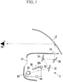
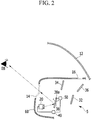
1 und2 sind beispielhafte schematische Darstellungen einer Anzeigevorrichtung für ein Fahrzeug gemäß einem Ausführungsbeispiel der vorliegenden Erfindung; und1 and2 are exemplary schematic representations of a display device for a vehicle according to an embodiment of the present invention; and -
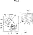
3 ist eine beispielhafte schematisches Darstellung einer Laserscanprojektionsvorrichtung gemäß einem Ausführungsbeispiel der vorliegenden Erfindung.3 FIG. 3 is an exemplary schematic illustration of a laser scan projection apparatus according to an exemplary embodiment of the present invention.
BezugszeichenlisteList of reference symbols
- 55
- AnzeigevorrichtungDisplay device
- 1212th
- Erste gewölbte ScheibeFirst domed disc
- 1414th
- Zweite gewölbte ScheibeSecond domed disc
- 2020th
- LaserscanprojektionsvorrichtungLaser scanning projection device
- 3232
- Erster SpiegelFirst mirror
- 3434
- Zweiter SpiegelSecond mirror
- 3636
- Dritter SpiegelThird mirror
- 3838
- Vierter SpiegelFourth mirror
- 4040
- Steuerungsteering
- 5050
- Motorengine
- 6060
- Armaturenbrettdashboard
Ausführliche Beschreibung bevorzugter AusführungsformenDetailed description of preferred embodiments
Es wird hier so verstanden, dass der Begriff „Fahrzeug“ oder „fahrzeug“ oder andere ähnliche Ausdrücke, wie sie hier verwendet werden, Motorfahrzeuge im Allgemeinen, wie z.B. Automobile beinhaltend Sports Utility Vehicles (SUV), Busse, LKW, verschiedene kommerzielle Fahrzeuge, Wasserfahrzeuge beinhaltend eine Vielfalt von Booten und Schiffen, Flugzeuge und dergleichen, Hybridfahrzeuge, elektrische Fahrzeuge, Verbrennungs- und hybridelektrische Fahrzeuge, wasserstoffgetriebene Fahrzeuge und andere mit alternativen Treibstoffen (z.B. Treibstoffe, die aus anderen Rohstoffen als Öl hergestellt sind) betriebene Fahrzeuge mit einschließen.It is understood here that the term "vehicle" or "vehicle" or other similar expressions as used herein, motor vehicles in general, such as automobiles including sports utility vehicles (SUV), buses, trucks, various commercial vehicles, Watercraft including a variety of boats and ships, airplanes and the like, hybrid vehicles, electric vehicles, combustion and hybrid electric vehicles, hydrogen-powered vehicles, and other vehicles powered by alternative fuels (e.g., fuels made from raw materials other than oil).
Obwohl eine beispielhafte Ausführungsform beschrieben wird, wobei eine Anzahl an Baugruppen zur Ausführung des beispielhaften Verfahrens verwendet wird, soll es so zu verstehen sein, dass das beispielhafte Verfahren auch durch ein oder eine Mehrzahl an Modulen ausgeführt werden kann. Ferner soll es so verstanden werden, dass der Ausdruck „Steuerungseinheit“ sich auf eine Hardwarevorrichtung bezieht, die Arbeitsspeicher und einen Prozessor beinhaltet. Der Arbeitsspeicher ist eingerichtet, Module zu speichern und der Prozessor ist insbesondere eingerichtet, diese Module auszuführen, um ein oder mehrere Verfahren durchzuführen, die weiter unten beschrieben sind.Although an exemplary embodiment is described, wherein a number of assemblies are used to carry out the exemplary method, it is to be understood that the exemplary method can also be carried out by one or a plurality of modules. Furthermore, it should be understood that the term “control unit” refers to a hardware device that includes memory and a processor. The main memory is set up to store modules and the processor is set up, in particular, to execute these modules in order to carry out one or more methods which are described below.
Die Terminologie, die hierin verwendet wird, dient dem Zweck, lediglich einzelne Ausführungsformen zu beschreiben und ist nicht vorgesehen, die Erfindung einzuschränken. Die hierin verwendeten Singularformen „ein“, und „die“ sollen Pluralformen auch einschließen, es sei denn, dass der Kontext dem klar widerspricht. Es soll ferner verstanden werden, dass die Begriffe „aufweist“ und/oder „aufweisen“, wenn sie in der Beschreibung verwendet werden, das Vorhandensein von angegebenen Merkmalen, Zahlen, Verfahrensschritten, Elementen und/oder Komponenten angeben, aber nicht das Vorhandensein oder die Ergänzung von ein oder mehreren anderen Merkmalen, Zahlen, Verfahrensschritten, Elementen, Komponenten und/oder Gruppen davon bedingen. Der Begriff „und/oder“ wie er hierin verwendet wird, beinhaltet alle Kombinationen von einem oder mehreren der jeweils aufgelisteten Elemente.The terminology used herein is for the purpose of describing only individual embodiments and is not intended to limit the invention. The singular forms “a” and “the” used herein are intended to include plural forms, unless the context clearly contradicts it. It should also be understood that the terms “has” and / or “have”, when used in the description, indicate the presence of specified features, numbers, method steps, elements and / or components, but not the presence or the Addition of one or more other features, numbers, process steps, elements, components and / or groups thereof require. The term “and / or” as used herein includes all combinations of one or more of the elements listed in each case.
Ferner kann die Steuerungslogik der vorliegenden Erfindung als nicht übertragbares computerlesbares Medium auf einem computerlesbaren Medium realisiert sein und ausführbare Programmbefehle zum Ausführen auf einem Prozessor, Controller oder Dergleichen enthalten. Beispiele des computerlesbaren Mediums beinhalten, sind aber nicht beschränkt auf: ROM, RAM, Compact Disc (CD)-ROMs, Magnetbänder, Disketten, Flash-Laufwerke, Smartcards und optische Datenspeichervorrichtungen. Das computerlesbare Aufnahmemedium kann auch in Netzwerk gekoppelten Computersystemen zur Verfügung gestellt werden, so dass das computerlesbare Medium in einer verteilten Weise gespeichert und ausgeführt werden kann, z.B. durch einen Telematic Server oder ein Controller Area Network (CAN).Furthermore, the control logic of the present invention can be implemented as a non-transferable computer-readable medium on a computer-readable medium and contain executable program instructions for execution on a processor, controller or the like. Examples of the computer readable medium include, but are not limited to: ROM, RAM, compact disc (CD) ROMs, magnetic tapes, floppy disks, flash drives, smart cards, and optical data storage devices. The computer-readable recording medium can also be made available in network-coupled computer systems, so that the computer-readable medium is stored and executed in a distributed manner can be, e.g. by a Telematic Server or a Controller Area Network (CAN).
Sofern nicht jeweils angegeben oder offensichtlich aus dem Kontext, wird der hier verwendete Ausdruck „etwa“ als innerhalb einer normalen Toleranz in der Technik, z.B. innerhalb von zwei Standardabweichungen vom Mittel angenommen. Somit kann „etwa“ als innerhalb von 10%, 9%, 8%, 7%, 6%, 5%, 4%, 3%, 2%, 1%, 0,5%, 0,1%, 0,05% oder 0,01% des genannten Wertes verstanden werden. Sofern es nicht anderweitig aus dem Kontext klar wird, werden alle numerischen Werte, die hier vorgesehen werden, als durch den Ausdruck „etwa“ modifiziert angesehen.Unless stated in each case or obvious from the context, the term "about" as used herein is assumed to be within a normal tolerance in the art, e.g., within two standard deviations from the mean. Thus "about" can be understood as within 10%, 9%, 8%, 7%, 6%, 5%, 4%, 3%, 2%, 1%, 0.5%, 0.1%, 0, 05% or 0.01% of the stated value. Unless the context indicates otherwise, all numerical values provided herein are deemed to have been modified by the term "about".
Wie in
Die erste gewölbte Scheibe
Ferner können die Bilder, die auf die zweite gewölbte Scheibe
Mit Bezug auf
Der Laserstrahlbündler 220 kann eingerichtet sein, Laserstrahlen zu bündeln, die von dem Laserstrahlgenerator 210 projiziert werden. Der Laserstrahlbündler 220 kann eingerichtet sein, die von dem Laserstrahlgenerator 210 abgegebenen Laserstrahlen zu dem MEMS-Scanner 230 durch einen einzigen Weg durchzulassen. Der Laserstrahlbündler 220 kann eine Mehrzahl an Kollimatorlinsen 225a, 225b und 225c aufweisen und eine Mehrzahl von dichroitischen Spiegeln 220a, 220b und 220c aufweisen. Die Mehrzahl an Kollimatorlinsen 225a, 225b und 225c kann in einer Projektionsrichtung der Laserstrahlen, die von dem Laserstrahlgenerator 210 projiziert werden, angeordnet sein. Die Mehrzahl an Kollimatorlinsen 225a, 225b und 225c kann eingerichtet sein, die Laserstrahlen zu brechen, um parallele Laserstrahlen zu erzeugen.The
Ein dichroitischer Spiegel kann eingerichtet sein, Laserstrahlen in einem spezifischen Frequenzband zu reflektieren und Laserstrahlen mit anderen Frequenzen als das spezifische Frequenzband durchzulassen (z.B. den Laserstrahlen erlauben dort durchzugehen). Insbesondere kann der dichroitische Spiegel 220a, der der Projektionsrichtung der roten Laserquelle 210a entspricht, eingerichtet sein, Laserstrahlen in einem roten Frequenzband zu reflektieren und Laserstrahlen mit anderen Frequenzen als das rote Frequenzband durchzulassen. Der dichroitische Spiegel 220b, der der Projektionsrichtung der grünen Laserquelle 210b entspricht, kann eingerichtet sein, Laserstrahlen in einem grünen Frequenzband zu reflektieren und Laserstrahlen mit anderen Frequenzen als dem grünen Frequenzband durchzulassen. Der dichroitische Spiegel 220c, der der Projektionsrichtung der blauen Laserquelle 210c entspricht, kann eingerichtet sein, Laserstrahlen in einem blauen Frequenzband zu reflektieren und Laserstrahlen mit anderen Frequenzen als dem blauen Frequenzband durchzulassen.A dichroic mirror can be set up to reflect laser beams in a specific frequency band and to allow laser beams with frequencies other than the specific frequency band to pass through (e.g. allowing the laser beams to pass through there). In particular, the
Jeder der dichroitischen Filter 220a, 220b und 220c kann eingerichtet sein, Laserstrahlen in Richtung auf den MEMS-Scanner 230 zu zu reflektieren. Der MEMS-Scanner 230 kann einen MEMS-Spiegel 235 aufweisen, der eingerichtet ist, Laserstrahlen entlang der X-Achsenrichtung und der Y-Achsenrichtung zu erfassen und einen Antriebsbereich (nicht dargestellt) aufweisen, der mit der Steuerung
Die Steuerung
Die Steuerung
Die Steuerung
Die Steuerung
Ein Motor
Die Steuerung
Wie oben beschrieben wurde, kann es gemäß einer beispielhaften Ausführungsform der vorliegenden Erfindung möglich sein, gleichzeitig mehrere verschiedene Bilder unter Verwendung einer einzelnen Laserscanprojektionsvorrichtung
Claims (15)
Applications Claiming Priority (2)
| Application Number | Priority Date | Filing Date | Title |
|---|---|---|---|
| KR1020130157983A KR101518932B1 (en) | 2013-12-18 | 2013-12-18 | Display apparatus for vehicle |
| KR10-2013-0157983 | 2013-12-18 |
Publications (2)
| Publication Number | Publication Date |
|---|---|
| DE102014213552A1 DE102014213552A1 (en) | 2015-06-18 |
| DE102014213552B4 true DE102014213552B4 (en) | 2021-10-07 |
Family
ID=53192866
Family Applications (1)
| Application Number | Title | Priority Date | Filing Date |
|---|---|---|---|
| DE102014213552.4A Expired - Fee Related DE102014213552B4 (en) | 2013-12-18 | 2014-07-11 | Display device and display method for a vehicle |
Country Status (4)
| Country | Link |
|---|---|
| US (1) | US9081180B2 (en) |
| KR (1) | KR101518932B1 (en) |
| CN (1) | CN104730712A (en) |
| DE (1) | DE102014213552B4 (en) |
Families Citing this family (21)
| Publication number | Priority date | Publication date | Assignee | Title |
|---|---|---|---|---|
| KR101640053B1 (en) * | 2015-01-02 | 2016-07-18 | 현대자동차주식회사 | Display device for vehicle and vehicle comprising the same |
| KR20170014497A (en) * | 2015-07-30 | 2017-02-08 | 주식회사 코리아하이텍 | Projector display device for using vehicle |
| DE202015008142U1 (en) * | 2015-11-26 | 2017-04-13 | Gm Global Technology Operations, Llc | Head-up display of a motor vehicle and motor vehicle |
| CN105652443B (en) * | 2016-01-08 | 2018-09-28 | 北京乐驾科技有限公司 | A kind of paths system, method and device based on HUD |
| WO2017199441A1 (en) * | 2016-05-20 | 2017-11-23 | 日立マクセル株式会社 | Projection optical system, head-up display device, and automobile |
| US9959818B2 (en) | 2016-09-22 | 2018-05-01 | Microsoft Technology Licensing, Llc | Display engines for use with optical waveguides |
| CN107870420A (en) * | 2016-09-27 | 2018-04-03 | 上海蔚兰动力科技有限公司 | The adjustable reflector of head-up display device and include its head-up display device |
| CN108107575A (en) * | 2016-11-25 | 2018-06-01 | 矽创电子股份有限公司 | Optical imaging device |
| EP3581984A4 (en) * | 2017-03-14 | 2021-01-13 | Pioneer Corporation | DISPLAY DEVICE |
| JP7005107B2 (en) * | 2017-10-20 | 2022-02-04 | 矢崎総業株式会社 | Display device for vehicles |
| DE102017130376B4 (en) * | 2017-12-18 | 2020-12-24 | Valeo Schalter Und Sensoren Gmbh | Display device as a head-up display with simple eyebox displacement |
| US11378800B2 (en) | 2018-01-11 | 2022-07-05 | Samsung Electronics Co., Ltd. | Image display apparatus |
| JP7354797B2 (en) * | 2019-11-27 | 2023-10-03 | 株式会社リコー | Optical deflectors, deflection devices, distance measuring devices, image projection devices, and vehicles |
| CN113495423B (en) * | 2020-04-01 | 2022-05-31 | 宁波舜宇车载光学技术有限公司 | Projection equipment and projection method |
| CN111458862A (en) * | 2020-05-13 | 2020-07-28 | 苏州路之遥科技股份有限公司 | Plane reflection type image display device |
| KR20220054492A (en) * | 2020-10-23 | 2022-05-03 | 삼성디스플레이 주식회사 | multi display panel assembled display |
| CN113031280A (en) * | 2021-04-13 | 2021-06-25 | 上海天马微电子有限公司 | Display device and imaging system |
| US11803110B2 (en) * | 2021-04-14 | 2023-10-31 | Coretronic Corporation | Projection device |
| CN114035324B (en) * | 2021-10-31 | 2023-09-22 | 东风商用车有限公司 | HUD light path projection system and HUD light path projection method |
| CN117058992A (en) * | 2022-06-01 | 2023-11-14 | 北京罗克维尔斯科技有限公司 | Projection control method of HUD device, HUD device and vehicle |
| CN115016125A (en) * | 2022-07-07 | 2022-09-06 | 业成科技(成都)有限公司 | Image generation module, head-up display system and vehicle |
Citations (3)
| Publication number | Priority date | Publication date | Assignee | Title |
|---|---|---|---|---|
| US20090160736A1 (en) | 2007-12-19 | 2009-06-25 | Hitachi, Ltd. | Automotive head up display apparatus |
| JP2010274803A (en) | 2009-05-29 | 2010-12-09 | Kanto Auto Works Ltd | Vehicular display device |
| EP2546087A1 (en) | 2010-03-11 | 2013-01-16 | Toyota Jidosha Kabushiki Kaisha | Image position adjustment device |
Family Cites Families (13)
| Publication number | Priority date | Publication date | Assignee | Title |
|---|---|---|---|---|
| FR2578330B1 (en) * | 1985-03-01 | 1989-03-31 | Thomson Csf | AIRPORT SYSTEM FOR VIEWING COLLIMATED IMAGES |
| CN1906950A (en) * | 2003-12-31 | 2007-01-31 | 讯宝科技公司 | Method and apparatus for controllably compensating for distortion in laser projection displays |
| KR20080050669A (en) | 2006-12-04 | 2008-06-10 | 엘지전자 주식회사 | Car Head Up Display Device |
| KR20100078688A (en) * | 2008-12-30 | 2010-07-08 | 송혁규 | Apparatus and method for dislpaying for projection |
| KR101182154B1 (en) | 2010-06-16 | 2012-09-13 | 한국건설기술연구원 | Head up display of transportation equipment and its operation control method |
| DE102010013241A1 (en) * | 2010-03-29 | 2011-09-29 | Audi Ag | Device for displaying information in a motor vehicle |
| JP5093279B2 (en) * | 2010-03-30 | 2012-12-12 | 株式会社デンソー | Head-up display device for vehicle |
| FR2960309B1 (en) * | 2010-05-20 | 2013-06-28 | Delphi Tech Inc | HIGH HEAD DISPLAY SYSTEM |
| WO2012035623A1 (en) | 2010-09-15 | 2012-03-22 | パイオニア株式会社 | Display device |
| KR20120051831A (en) * | 2010-11-15 | 2012-05-23 | 삼성전자주식회사 | Projector and driving method thereof |
| KR20120062521A (en) * | 2010-12-06 | 2012-06-14 | 현대자동차주식회사 | Display system for vehicle |
| JP5370427B2 (en) | 2011-07-24 | 2013-12-18 | 株式会社デンソー | Head-up display device |
| CN102514492B (en) * | 2011-11-22 | 2014-05-07 | 苏州科雷芯电子科技有限公司 | Vehicle dashboard based on visual technology of machine |
-
2013
- 2013-12-18 KR KR1020130157983A patent/KR101518932B1/en not_active Expired - Fee Related
-
2014
- 2014-06-10 US US14/300,510 patent/US9081180B2/en active Active
- 2014-07-11 DE DE102014213552.4A patent/DE102014213552B4/en not_active Expired - Fee Related
- 2014-08-13 CN CN201410397863.7A patent/CN104730712A/en active Pending
Patent Citations (3)
| Publication number | Priority date | Publication date | Assignee | Title |
|---|---|---|---|---|
| US20090160736A1 (en) | 2007-12-19 | 2009-06-25 | Hitachi, Ltd. | Automotive head up display apparatus |
| JP2010274803A (en) | 2009-05-29 | 2010-12-09 | Kanto Auto Works Ltd | Vehicular display device |
| EP2546087A1 (en) | 2010-03-11 | 2013-01-16 | Toyota Jidosha Kabushiki Kaisha | Image position adjustment device |
Also Published As
| Publication number | Publication date |
|---|---|
| US20150168718A1 (en) | 2015-06-18 |
| DE102014213552A1 (en) | 2015-06-18 |
| KR101518932B1 (en) | 2015-05-11 |
| CN104730712A (en) | 2015-06-24 |
| US9081180B2 (en) | 2015-07-14 |
Similar Documents
| Publication | Publication Date | Title |
|---|---|---|
| DE102014213552B4 (en) | Display device and display method for a vehicle | |
| EP3847499B1 (en) | Method for operating a field-of-vision display device for a motor vehicle | |
| DE102012107423B4 (en) | Head-up display device with a screen element with a plurality of optical elements | |
| EP3254152B1 (en) | Device for projecting data by means of holographic optical elements | |
| DE102014213057B4 (en) | Head-up display device and display unit | |
| DE69624774T2 (en) | Backlit color display | |
| DE102011083662B4 (en) | Display apparatus for an occupant of a vehicle, vehicle and method for generating a display in an occupant's field of view | |
| DE102012107424A1 (en) | Head-up display device, screen element, manufacturing method therefor, and image projection method | |
| DE102014003351B4 (en) | Head-up display and display method | |
| DE102012107066A1 (en) | Head-up display device | |
| EP1347641A1 (en) | Free projection display device | |
| EP2894509A1 (en) | Field of vision display for a vehicle for displaying image information in two independent images to a viewer | |
| DE102016203789A1 (en) | Windscreen display for a vehicle and control method therefor | |
| DE112015001200T5 (en) | Light emitting vehicle display device and vehicle display system | |
| DE112015002814T5 (en) | Display device for virtual images | |
| EP3837577A2 (en) | Method for operating a visual field display device for a motor vehicle | |
| DE102014213355B4 (en) | Display unit with a head-up display device | |
| DE102012211729A1 (en) | Camera system for detecting the position of a driver of a motor vehicle | |
| DE112015002481T5 (en) | Head-up display device | |
| DE102016111119A1 (en) | Laser projection device and method for generating virtual images | |
| DE69123322T2 (en) | Head-up display for displaying data on board a car | |
| DE102019121048A1 (en) | Waveguide-based direct view display | |
| DE202016000640U1 (en) | Head-up display of a motor vehicle and motor vehicle | |
| DE212024000284U1 (en) | Rearview arrangement for a vehicle with a visibly opaque optical element for reflecting infrared light | |
| DE102020103964A1 (en) | Field of view display device with a height offset device for a vehicle |
Legal Events
| Date | Code | Title | Description |
|---|---|---|---|
| R083 | Amendment of/additions to inventor(s) | ||
| R012 | Request for examination validly filed | ||
| R016 | Response to examination communication | ||
| R018 | Grant decision by examination section/examining division | ||
| R020 | Patent grant now final | ||
| R119 | Application deemed withdrawn, or ip right lapsed, due to non-payment of renewal fee |