DE102013217841B4 - Cylinder, comprising a cylinder tube and a closing element and method for producing a cylinder - Google Patents
Cylinder, comprising a cylinder tube and a closing element and method for producing a cylinder Download PDFInfo
- Publication number
- DE102013217841B4 DE102013217841B4 DE102013217841.7A DE102013217841A DE102013217841B4 DE 102013217841 B4 DE102013217841 B4 DE 102013217841B4 DE 102013217841 A DE102013217841 A DE 102013217841A DE 102013217841 B4 DE102013217841 B4 DE 102013217841B4
- Authority
- DE
- Germany
- Prior art keywords
- cylinder
- cylinder tube
- closing element
- curl
- groove
- Prior art date
- Legal status (The legal status is an assumption and is not a legal conclusion. Google has not performed a legal analysis and makes no representation as to the accuracy of the status listed.)
- Active
Links
- 238000004519 manufacturing process Methods 0.000 title claims abstract description 8
- 230000000284 resting effect Effects 0.000 claims abstract 2
- 239000000463 material Substances 0.000 claims description 4
- 229910001220 stainless steel Inorganic materials 0.000 claims description 4
- 239000010935 stainless steel Substances 0.000 claims description 4
- 230000007704 transition Effects 0.000 abstract description 11
- 238000007789 sealing Methods 0.000 description 3
- 239000000126 substance Substances 0.000 description 2
- 230000006978 adaptation Effects 0.000 description 1
- 230000015572 biosynthetic process Effects 0.000 description 1
- 238000004140 cleaning Methods 0.000 description 1
- 230000007797 corrosion Effects 0.000 description 1
- 238000005260 corrosion Methods 0.000 description 1
- 230000006735 deficit Effects 0.000 description 1
- 230000003670 easy-to-clean Effects 0.000 description 1
- 230000000694 effects Effects 0.000 description 1
- 230000010354 integration Effects 0.000 description 1
- 238000000034 method Methods 0.000 description 1
- 238000000465 moulding Methods 0.000 description 1
- 238000005096 rolling process Methods 0.000 description 1
Images
Classifications
-
- F—MECHANICAL ENGINEERING; LIGHTING; HEATING; WEAPONS; BLASTING
- F15—FLUID-PRESSURE ACTUATORS; HYDRAULICS OR PNEUMATICS IN GENERAL
- F15B—SYSTEMS ACTING BY MEANS OF FLUIDS IN GENERAL; FLUID-PRESSURE ACTUATORS, e.g. SERVOMOTORS; DETAILS OF FLUID-PRESSURE SYSTEMS, NOT OTHERWISE PROVIDED FOR
- F15B15/00—Fluid-actuated devices for displacing a member from one position to another; Gearing associated therewith
- F15B15/08—Characterised by the construction of the motor unit
- F15B15/14—Characterised by the construction of the motor unit of the straight-cylinder type
- F15B15/1423—Component parts; Constructional details
- F15B15/1438—Cylinder to end cap assemblies
Landscapes
- Engineering & Computer Science (AREA)
- Physics & Mathematics (AREA)
- Fluid Mechanics (AREA)
- Mechanical Engineering (AREA)
- General Engineering & Computer Science (AREA)
- Actuator (AREA)
Abstract
Die Erfindung betrifft einen Zylinder, aufweisend ein von einem Medium druckbeaufschlagtes Zylinderrohr 2 und ein Abschlusselement 1, wobei ein Endbereich des Zylinderrohrs 2 eine in eine Nut 8 des Abschlusselements 1 eingreifende Einrollung 13 aufweist. Erfindungsgemäß wird ein Zylinder, aufweisend zumindest ein Zylinderrohr 2 sowie ein Abschlusselement 1, bereitgestellt, der bei einer einfachen Herstellbarkeit glatte Übergänge aufweist. Erreicht wird dies dadurch, dass die Nut 8 beabstandet zu einem ringförmigen Anschlag 7 des Abschlusselements 1 angeordnet ist, und dass die Einrollung 13 des Zylinderrohrs 2 in die Nut 8 beabstandet zu einer an dem Anschlag 7 anliegenden Stirnseite 11 des Zylinderrohrs 2 angeordnet ist. Zudem ist im Bereich des Stoßes des Zylinderrohrs 2 an dem Abschlusselement 1 eine Konturausgleichseinrollung 14 vorhanden.The invention relates to a cylinder having a cylinder tube 2 pressurized by a medium and a closing element 1, one end region of the cylinder tube 2 having a curl 13 engaging in a groove 8 of the closing element 1. According to the invention, a cylinder having at least one cylinder tube 2 and a closing element 1 is provided which has smooth transitions while being simple to manufacture. This is achieved by the fact that the groove 8 is arranged at a distance from an annular stop 7 of the closing element 1, and that the curl 13 of the cylinder tube 2 is arranged in the groove 8 at a distance from an end face 11 of the cylinder tube 2 resting against the stop 7. In addition, a contour compensation curl 14 is present in the area of the joint of the cylinder tube 2 on the closing element 1.
Description
Gebiet der ErfindungField of the invention
Die Erfindung betrifft einen Zylinder, aufweisend zumindest ein von einem Medium druckbeaufschlagtes Zylinderrohr und ein Abschlusselement, wobei zumindest ein Endbereich des Zylinderrohrs eine in eine Nut des Abschlusselements eingreifende Einrollung aufweist. Weiterhin betrifft die Erfindung ein Verfahren zum Herstellen eines derartigen Zylinders.The invention relates to a cylinder having at least one cylinder tube pressurized by a medium and a closing element, at least one end region of the cylinder tube having a curl that engages in a groove of the closing element. The invention also relates to a method for producing such a cylinder.
Hintergrund der ErfindungBackground of the invention
Ein derartiger Zylinder ist aus der
Die
Der Erfindung liegt die Aufgabe zugrunde, einen Zylinder mit einer Verbindung eines Zylinderrohrs mit einem Abschlusselement anzugeben, der bei einer einfachen Herstellbarkeit glatte Übergänge aufweist.The invention is based on the object of specifying a cylinder with a connection of a cylinder tube with a closing element, which has smooth transitions while being easy to manufacture.
Offenbarung der ErfindungDisclosure of the invention
Vorteile der ErfindungAdvantages of the invention
Diese Aufgabe wird dadurch gelöst, dass die Nut beabstandet zu einem ringförmigen Anschlag des Abschlusselements angeordnet ist und dass die Einrollung des Zylinderrohrs in die Nut benachbart zu einer an dem Anschlag angrenzenden Stirnseite des Zylinderrohrs angeordnet ist. Das entsprechende Verfahren zum Herstellen des Zylinderrohrs beziehungsweise der Verbindung zwischen dem Abschlusselement und dem Zylinderrohr zeichnet sich dadurch aus, dass das Zylinderrohr in die beabstandet zu einem ringförmigen Anschlag angeordneten Nut mit einem benachbart zu einer an den Anschlag anliegenden Stirnseite des Zylinderrohrs liegenden Umfangsbereich eingerollt wird. Es wird folglich nicht das direkte Ende des Zylinderrohrs in eine Nut eingerollt, sondern die Stirnseite des Zylinderrohrs liegt bündig an einem Anschlag des Abschlusselementes an und beabstandet zu der Stirnseite wird eine in die umlaufende Nut in dem Abschlusselement eingreifende Einrollung in das Zylinderrohr eingearbeitet. Durch diese Ausgestaltung ist bei einer entsprechenden Anpassung der äußeren Durchmesser des Zylinderrohrs und der Abschlusselemente, die im Übrigen ein Boden oder ein Deckel sein können, und dem Zylinderrohr ein glatter Übergang gegeben. Dadurch, dass die Einrollung benachbart, aber beabstandet zu dem Stirnende des Zylinderrohrs angeordnet ist, ist einerseits eine zuverlässige Verbindung mit dem Abschlusselement erreicht, während andererseits diese Verbindung den glatten Übergang zwischen dem Zylinderrohr und dem Abschlusselement nicht beeinträchtigt. Im Übrigen ist die erfindungsgemäße Verbindung des Zylinderrohrs mit dem Abschlusselement bei einem beliebig anzuwendenden Zylinder umsetzbar, wobei aber bevorzugt der Zylinder ein Pneumatikzylinder ist. In dem so ausgebildeten Pneumatikzylinder ist ein mit einer Kolbenstange verbundener Kolben zwischen zwei Endlagen hin und her bewegbar. Der so ausgebildete Pneumatikzylinder ist wiederum bei allen denkbaren industriellen Anwendungen einsetzbar. Bevorzugt wird der Pneumatikzylinder aber in der Lebensmittelindustrie, der Pharmaindustrie und/oder der Chemieindustrie eingesetzt. Bei allen diesen Anwendungen ist es erstrebenswert, eine möglichst einfache und gründliche Reinigung der verwendeten Bauteile zu gewährleisen. Dies ist durch die dargestellte Verbindung des Zylinderrohrs mit dem Abschlusselement gegeben, da zwischen den Bauteilen ein glatter Übergang ohne Absätze, Kanten oder Kerben gegeben ist.This object is achieved in that the groove is arranged at a distance from an annular stop of the terminating element and that the curling of the cylinder tube into the groove is arranged adjacent to an end face of the cylinder tube adjoining the stop. The corresponding method for producing the cylinder tube or the connection between the closing element and the cylinder tube is characterized in that the cylinder tube is rolled into the groove spaced apart from an annular stop with a circumferential area adjacent to an end face of the cylinder tube lying against the stop. As a result, the direct end of the cylinder tube is not rolled into a groove, but the end face of the cylinder tube rests flush against a stop of the closing element and, at a distance from the end face, a roll engaging the circumferential groove in the closing element is worked into the cylinder tube. With a corresponding adaptation of the outer diameter of the cylinder tube and the closing elements, which can also be a base or a cover, and the cylinder tube, a smooth transition is provided by this configuration. Because the curl is arranged adjacent to but spaced from the front end of the cylinder tube, on the one hand a reliable connection to the terminating element is achieved, while on the other hand this connection does not impair the smooth transition between the cylinder tube and the terminating element. In addition, the connection according to the invention of the cylinder tube with the closing element can be implemented with any cylinder that can be used, but the cylinder is preferably a pneumatic cylinder. In the pneumatic cylinder designed in this way, a piston connected to a piston rod can be moved back and forth between two end positions. The pneumatic cylinder designed in this way can in turn be used in all conceivable industrial applications. However, the pneumatic cylinder is preferably used in the food industry, the pharmaceutical industry and / or the chemical industry. In all of these applications, it is desirable to ensure that the components used are cleaned as simply and thoroughly as possible. This is given by the connection shown between the cylinder tube and the closing element, since there is a smooth transition between the components without any shoulders, edges or notches.
In Weiterbildung der Erfindung ist im Bereich des Stoßes des Zylinderrohrs an dem Abschlusselement eine Konturausgleichseinrollung vorhanden. Diese Konturausgleichseinrollung wird zu gleichen oder ungleichen Teilen in das Zylinderrohr und das anschließende Abschlusselement eingebracht und gewährleistet, dass die benachbarten Bauteile in jedem Falle glatt ineinander übergehen. Durch diese Ausgestaltung ist es weiterhin möglich, vorhandene Ungleichmäßigkeiten in den benachbarten Oberflächen des Abschlusselements und des Zylinderrohrs auszugleichen. Diese Ungleichmäßigkeiten können zufällig oder aber gewollt in den Bauteilen vorhanden sein. So ist es beispielsweise denkbar, in das grundsätzlich als zylinderförmiges Bauteil ausgebildete Abschlusselement einseitig oder beidseitig eine Abflachung einzuarbeiten, um beispielsweise eine lagegenaue Ausrichtung zu anderen Bauteilen zu gewährleisten. Im Bereich dieser Abflachung wird durch die Konturausgleichseinrollung insbesondere in das Zylinderrohr ein kantenfreier Übergang zwischen den benachbarten Bauteilen gewährleistet.In a further development of the invention, a contour compensation curl is present in the area of the joint of the cylinder tube on the terminating element. This contour compensation curl is in equal or unequal parts in the cylinder barrel and the subsequent closing element is introduced and ensures that the adjacent components merge smoothly into one another in any case. This configuration also makes it possible to compensate for existing irregularities in the adjacent surfaces of the closing element and of the cylinder tube. These irregularities can be present in the components accidentally or intentionally. For example, it is conceivable to incorporate a flattening on one or both sides of the terminating element, which is basically designed as a cylindrical component, in order, for example, to ensure precise alignment with other components. In the area of this flattened area, the contour compensation curl ensures an edge-free transition between the adjacent components, especially in the cylinder tube.
In weiterer Ausgestaltung der Erfindung ist die Einrolltiefe beziehungsweise der Einrollradius der Einrollung größer als die/der der Konturausgleichseinrollung. Dadurch ist einerseits sichergestellt, dass durch die größere Einrolltiefe der Einrollung eine zuverlässige Verbindung des Zylinderrohrs mit dem Abschlusselement hergestellt ist, und andererseits die Konturausgleichseinrollung nur eine solche Einrolltiefe aufweist, dass ein zuverlässiger Konturausgleich erfolgt. Dadurch ist auch der Herstellungsaufwand minimiert.In a further embodiment of the invention, the depth of curl or the radius of curl of the curl is greater than that of the contour compensation curl. This ensures, on the one hand, that the greater depth of curl of the curl creates a reliable connection between the cylinder tube and the closing element, and, on the other hand, the contour compensation curl has only such a depth of curl that a reliable contour compensation takes place. This also minimizes the manufacturing effort.
In Weiterbildung der Erfindung sind die Einrollung und/oder die Konturausgleichseinrollung kerbenfrei ausgebildet. Kerbenfrei bedeutet in diesem Zusammenhang, dass die Einrollung beziehungsweise die Konturausgleichseinrollung nicht mit einem spitzen, eine Kerbe in dem Zylinderrohr verursachenden, Werkzeug hergestellt wird, sondern mit einem Werkzeug, das beispielsweise eine abgerundete Oberfläche aufweist. Auch dadurch ist sichergestellt, dass zwar eine gebogene, aber glatte, Oberfläche erzeugt wird.In a further development of the invention, the curl and / or the contour compensation curl are designed without notches. Notch-free means in this context that the curling or the contour compensation curling is not produced with a pointed tool causing a notch in the cylinder tube, but with a tool that has a rounded surface, for example. This also ensures that a curved, but smooth, surface is produced.
In Weiterbildung der Erfindung weist das Abschlusselement benachbart zu der Nut eine endseitige mit dem Zylinderrohr zusammenwirkende Verdrehsicherung auf. Diese Verdrehsicherung bewirkt, dass sehr hohe Verdrehmomente zwischen dem Abschlusselement und dem Zylinderrohr übertragbar sind, ohne dass die Einrollung mit einem hohen Verformungsaufwand zur Herstellung einer verdrehfesten Verbindung ausgeführt werden muss.In a further development of the invention, the closing element has, adjacent to the groove, an anti-rotation device at the end that interacts with the cylinder tube. This anti-twist device ensures that very high torques can be transmitted between the closing element and the cylinder tube without the need for the curling to be carried out with a high deformation effort in order to produce a torsion-proof connection.
In Weiterbildung der Erfindung ist die Verdrehsicherung in Form einer Verzahnung ausgeführt. Die Verzahnung kann verschiedenartige, gegebenenfalls an die Werkstoffe der zu verbindenden Bauteile angepasste Kontur aufweisen. Dabei weist das Zylinderrohr eine innere Kontur mit einem geringfügig geringeren Innendurchmesser auf, als der Außendurchmesser der Verdrehsicherung. Demzufolge wird bei der Herstellung der Verbindung das Zylinderrohr bis zur Anlage der Stirnseite des Zylinderrohrs an den Anschlag auf das Abschlusselement und insbesondere die Verdrehsicherung aufgepresst. Dadurch, dass die so hergestellte Kerbverbindung innenliegend ist, ist keine Beeinträchtigung der glatten Außenoberfläche gegeben.In a further development of the invention, the anti-rotation device is designed in the form of a tooth system. The toothing can have different types of contour, possibly adapted to the materials of the components to be connected. The cylinder tube has an inner contour with a slightly smaller inner diameter than the outer diameter of the anti-rotation device. Accordingly, when establishing the connection, the cylinder tube is pressed onto the end element and in particular the anti-rotation device until the end face of the cylinder tube rests against the stop. Because the notch connection produced in this way is on the inside, there is no impairment of the smooth outer surface.
In weiterer Ausgestaltung der Erfindung ist das Material des Zylinderrohrs und/oder des Abschlusselements Edelstahl. Edelstahl eignet sich ganz besonders zur Herstellung eines Pneumatikzylinders, da er die notwendige Festigkeit hat, korrosionsbeständig ist, und aufgrund seiner glatten Oberfläche leicht zu reinigen ist.In a further embodiment of the invention, the material of the cylinder tube and / or of the closing element is stainless steel. Stainless steel is particularly suitable for the manufacture of a pneumatic cylinder, as it has the necessary strength, is corrosion-resistant and, thanks to its smooth surface, is easy to clean.
In Weiterbildung der Erfindung ist/sind das Abschlusselement und/oder das Zylinderrohr elektropoliert. Durch eine Elektropolitur wird eine besonders glatte, hygienische Oberfläche geschaffen, die aber beim gegenseitigen Zusammenwirken keine hohen Verdrehmomente übertragen können. Dadurch, dass aber zusätzlich eine Verdrehsicherung vorhanden ist, können auch bei einer solchermaßen ausgebildeten Oberfläche sehr hohe Verdrehmomente übertragen werden.In a further development of the invention, the closing element and / or the cylinder tube is / are electropolished. Electropolishing creates a particularly smooth, hygienic surface, which, however, cannot transmit high torques when interacting with one another. Since there is also an anti-twist device, very high torques can be transmitted even with a surface designed in this way.
Weitere vorteilhafte Ausgestaltungen der Erfindung sind der Zeichnungsbeschreibung zu entnehmen, in der in den Figuren dargestellte Ausführungsbeispiele näher beschrieben sind.Further advantageous embodiments of the invention can be found in the description of the drawings, in which the exemplary embodiments shown in the figures are described in more detail.
FigurenlisteFigure list
Es zeigen:
-
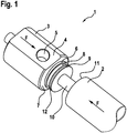
1 ein Abschlusselement, das ausgerichtet zu einem Zylinderrohr mit diesem zur Herstellung eines Zylinders verbunden wird, -
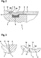
2 eine Schnittdarstellung eines Verbindungsbereichs eines mit einem Abschlusselement verbundenen Zylinderrohrs, wobei in das Zylinderrohr eine von einer Stirnseite des Zylinderrohrs beabstandete Einrollung und in den Übergangsbereich des Zylinderrohrs und des Abschlusselements eine Konturausgleichseinrollung eingebracht sind, -
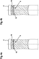
3 eine Ausschnittsvergrößerung aus2 vor und nach Anbringung einer Einrollung und einer Konturausgleichseinrollung und -
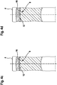
4a bis4d Schnittdarstellungen von verschiedenen Verdrehsicherungen des Abschlusselements gegenüber dem Zylinderrohr.
-
1 a closing element, which is aligned with a cylinder tube and connected to the latter to produce a cylinder, -
2 a sectional view of a connection area of a cylinder tube connected to a terminating element, a curl spaced from an end face of the cylinder tube and a contour compensation curl being introduced into the cylinder tube and the transition region of the cylinder tube and the terminating element, -
3 an enlargedsection 2 before and after applying a curl and a contour compensation curl and -
4a to4d Sectional representations of various anti-rotation devices of the closing element in relation to the cylinder barrel.
Ausführungsformen der ErfindungEmbodiments of the invention
Das Abschlusselement
Das zu dem Abschlusselement
Sowohl das Abschlusselement
Nachdem ausweislich der
Die
Claims (8)
Priority Applications (1)
| Application Number | Priority Date | Filing Date | Title |
|---|---|---|---|
| DE102013217841.7A DE102013217841B4 (en) | 2013-09-06 | 2013-09-06 | Cylinder, comprising a cylinder tube and a closing element and method for producing a cylinder |
Applications Claiming Priority (1)
| Application Number | Priority Date | Filing Date | Title |
|---|---|---|---|
| DE102013217841.7A DE102013217841B4 (en) | 2013-09-06 | 2013-09-06 | Cylinder, comprising a cylinder tube and a closing element and method for producing a cylinder |
Publications (2)
| Publication Number | Publication Date |
|---|---|
| DE102013217841A1 DE102013217841A1 (en) | 2015-03-12 |
| DE102013217841B4 true DE102013217841B4 (en) | 2021-05-20 |
Family
ID=52478426
Family Applications (1)
| Application Number | Title | Priority Date | Filing Date |
|---|---|---|---|
| DE102013217841.7A Active DE102013217841B4 (en) | 2013-09-06 | 2013-09-06 | Cylinder, comprising a cylinder tube and a closing element and method for producing a cylinder |
Country Status (1)
| Country | Link |
|---|---|
| DE (1) | DE102013217841B4 (en) |
Families Citing this family (1)
| Publication number | Priority date | Publication date | Assignee | Title |
|---|---|---|---|---|
| DE102014215579B4 (en) * | 2014-08-06 | 2017-12-14 | Suspa Gmbh | Piston-cylinder unit |
Citations (7)
| Publication number | Priority date | Publication date | Assignee | Title |
|---|---|---|---|---|
| US2580910A (en) * | 1949-02-08 | 1952-01-01 | S & C Electric Co | Contact construction |
| DE1231979B (en) * | 1965-01-28 | 1967-01-05 | Bosch Gmbh Robert | Working cylinder for pressure medium systems |
| DE2238211A1 (en) * | 1972-08-03 | 1974-02-14 | Haenchen Kg Herbert | PRESSURIZED CYLINDRICAL CONTAINER |
| DE4413279A1 (en) * | 1994-04-16 | 1995-10-19 | Guenther Hahn | Hydraulic powered actuator |
| DE19506479A1 (en) * | 1995-02-24 | 1996-08-29 | Suspa Compart Ag | Fluid-filled cylinder-piston rod unit, in particular gas spring |
| EP1128073A1 (en) * | 2000-02-28 | 2001-08-29 | Serta | Method of closing the end which forms the head or rod guide of the barrel of an actuator cylinder |
| DE60315038T2 (en) * | 2002-05-15 | 2008-04-10 | Enea-Ente Per Le Nouve Tecnologie, L'energia E L'ambiente | METHOD FOR CLOSING A HYDRAULIC, PNEUMATIC AND / OR HYDROPNEUMATIC CYLINDER AND DEVICE FOR CARRYING OUT THE METHOD |
-
2013
- 2013-09-06 DE DE102013217841.7A patent/DE102013217841B4/en active Active
Patent Citations (7)
| Publication number | Priority date | Publication date | Assignee | Title |
|---|---|---|---|---|
| US2580910A (en) * | 1949-02-08 | 1952-01-01 | S & C Electric Co | Contact construction |
| DE1231979B (en) * | 1965-01-28 | 1967-01-05 | Bosch Gmbh Robert | Working cylinder for pressure medium systems |
| DE2238211A1 (en) * | 1972-08-03 | 1974-02-14 | Haenchen Kg Herbert | PRESSURIZED CYLINDRICAL CONTAINER |
| DE4413279A1 (en) * | 1994-04-16 | 1995-10-19 | Guenther Hahn | Hydraulic powered actuator |
| DE19506479A1 (en) * | 1995-02-24 | 1996-08-29 | Suspa Compart Ag | Fluid-filled cylinder-piston rod unit, in particular gas spring |
| EP1128073A1 (en) * | 2000-02-28 | 2001-08-29 | Serta | Method of closing the end which forms the head or rod guide of the barrel of an actuator cylinder |
| DE60315038T2 (en) * | 2002-05-15 | 2008-04-10 | Enea-Ente Per Le Nouve Tecnologie, L'energia E L'ambiente | METHOD FOR CLOSING A HYDRAULIC, PNEUMATIC AND / OR HYDROPNEUMATIC CYLINDER AND DEVICE FOR CARRYING OUT THE METHOD |
Also Published As
| Publication number | Publication date |
|---|---|
| DE102013217841A1 (en) | 2015-03-12 |
Similar Documents
| Publication | Publication Date | Title |
|---|---|---|
| DE4343171C2 (en) | Blind rivet and process for its manufacture | |
| EP0343395B1 (en) | Pressfitting, tap and method of manufacture | |
| DE2740226C3 (en) | Constant velocity swivel | |
| DE69007382T2 (en) | Connector. | |
| DE3721577C2 (en) | ||
| WO2014000911A1 (en) | Connection device for pipe lines | |
| AT508455A1 (en) | PRESS FOR THE MANUFACTURE OF A TAMPON | |
| EP2304303A1 (en) | Press-on fitting for a pipe, in particular plastic pipe, or plastic-metal composite pipe | |
| DE3226868A1 (en) | PERMANENTLY TIGHT THREADED PIPE CONNECTION | |
| DE2137582A1 (en) | Connection device for hollow bars | |
| AT511387B1 (en) | DENTAL PROSTHESIS | |
| DE1652872B1 (en) | CONNECTION BETWEEN A CYLINDRICAL TUBE AND A CONNECTING PART PUSHED ON THIS | |
| DE102013217841B4 (en) | Cylinder, comprising a cylinder tube and a closing element and method for producing a cylinder | |
| WO2017029232A1 (en) | Gland system having a cable or hose gland | |
| AT517989B1 (en) | Method for surface compacting and calibrating a sintered component | |
| DE2350265A1 (en) | PIPE COUPLING AND SEAL WITH RELEASE RESISTANCE | |
| DE102007032861A1 (en) | Tensile pipe connection | |
| DE602004002083T2 (en) | O-ring for press connections | |
| DE202005012445U1 (en) | profile system | |
| DE202011003529U1 (en) | Device for connecting pipes | |
| DE19748623A1 (en) | Press connection | |
| DE2239168A1 (en) | CONNECTING A PLASTIC SOCKET TO A PLASTIC PIPE | |
| DE2700516A1 (en) | Socket or sleeve pipe coupling - has outer clamp ring with internal cones to successively deform outer coupling member | |
| DE102008036882A1 (en) | Cam shaft for valve gear of internal combustion engine, has elongated, tubular carrier body, on which three-dimensional cam body is fixed in axial and radial position for representation of defined control time | |
| DE10331233A1 (en) | ground roller |
Legal Events
| Date | Code | Title | Description |
|---|---|---|---|
| R081 | Change of applicant/patentee |
Owner name: AVENTICS GMBH, DE Free format text: FORMER OWNER: ROBERT BOSCH GMBH, 70469 STUTTGART, DE |
|
| R082 | Change of representative |
Representative=s name: BBS BIER BREHM SPAHN PARTNERSCHAFT RECHTSANWAE, DE |
|
| R081 | Change of applicant/patentee |
Owner name: AVENTICS GMBH, DE Free format text: FORMER OWNER: BOSCH REXROTH PNEUMATICS GMBH, 30880 LAATZEN, DE |
|
| R082 | Change of representative |
Representative=s name: BBS BIER BREHM SPAHN PARTNERSCHAFT RECHTSANWAE, DE |
|
| R081 | Change of applicant/patentee |
Owner name: AVENTICS GMBH, DE Free format text: FORMER OWNER: REXROTH PNEUMATICS GMBH, 30880 LAATZEN, DE |
|
| R082 | Change of representative |
Representative=s name: BBS BIER BREHM SPAHN PARTNERSCHAFT RECHTSANWAE, DE |
|
| R012 | Request for examination validly filed | ||
| R016 | Response to examination communication | ||
| R016 | Response to examination communication | ||
| R018 | Grant decision by examination section/examining division | ||
| R020 | Patent grant now final |