DE102012217841A1 - Apparatus and method for demonstrating the visual impression of a wearer of spectacles with polarizing spectacle lenses - Google Patents
Apparatus and method for demonstrating the visual impression of a wearer of spectacles with polarizing spectacle lenses Download PDFInfo
- Publication number
- DE102012217841A1 DE102012217841A1 DE102012217841.4A DE102012217841A DE102012217841A1 DE 102012217841 A1 DE102012217841 A1 DE 102012217841A1 DE 102012217841 A DE102012217841 A DE 102012217841A DE 102012217841 A1 DE102012217841 A1 DE 102012217841A1
- Authority
- DE
- Germany
- Prior art keywords
- image
- polarization
- polarizing
- polarization direction
- pixels
- Prior art date
- Legal status (The legal status is an assumption and is not a legal conclusion. Google has not performed a legal analysis and makes no representation as to the accuracy of the status listed.)
- Pending
Links
- 230000000007 visual effect Effects 0.000 title claims abstract description 27
- 238000000034 method Methods 0.000 title claims description 20
- 230000010287 polarization Effects 0.000 claims abstract description 289
- 239000011521 glass Substances 0.000 claims abstract description 46
- 230000003287 optical effect Effects 0.000 claims description 21
- 239000013598 vector Substances 0.000 claims description 18
- 238000011144 upstream manufacturing Methods 0.000 claims description 11
- 230000003213 activating effect Effects 0.000 claims description 7
- 239000003086 colorant Substances 0.000 claims description 4
- 230000005540 biological transmission Effects 0.000 description 20
- 230000000694 effects Effects 0.000 description 9
- 238000003384 imaging method Methods 0.000 description 8
- 230000005855 radiation Effects 0.000 description 7
- 238000012360 testing method Methods 0.000 description 7
- 230000008859 change Effects 0.000 description 4
- 230000003292 diminished effect Effects 0.000 description 4
- 230000005670 electromagnetic radiation Effects 0.000 description 4
- 239000004973 liquid crystal related substance Substances 0.000 description 4
- 239000011159 matrix material Substances 0.000 description 4
- 230000001179 pupillary effect Effects 0.000 description 4
- XLYOFNOQVPJJNP-UHFFFAOYSA-N water Substances O XLYOFNOQVPJJNP-UHFFFAOYSA-N 0.000 description 4
- 230000005684 electric field Effects 0.000 description 3
- 230000004438 eyesight Effects 0.000 description 3
- 230000002349 favourable effect Effects 0.000 description 3
- 239000000463 material Substances 0.000 description 3
- 238000002834 transmittance Methods 0.000 description 3
- 238000010521 absorption reaction Methods 0.000 description 2
- 230000004913 activation Effects 0.000 description 2
- 230000007547 defect Effects 0.000 description 2
- 230000001419 dependent effect Effects 0.000 description 2
- 230000006870 function Effects 0.000 description 2
- 230000004313 glare Effects 0.000 description 2
- 238000012986 modification Methods 0.000 description 2
- 230000004048 modification Effects 0.000 description 2
- 230000008569 process Effects 0.000 description 2
- 238000011179 visual inspection Methods 0.000 description 2
- BUHVIAUBTBOHAG-FOYDDCNASA-N (2r,3r,4s,5r)-2-[6-[[2-(3,5-dimethoxyphenyl)-2-(2-methylphenyl)ethyl]amino]purin-9-yl]-5-(hydroxymethyl)oxolane-3,4-diol Chemical compound COC1=CC(OC)=CC(C(CNC=2C=3N=CN(C=3N=CN=2)[C@H]2[C@@H]([C@H](O)[C@@H](CO)O2)O)C=2C(=CC=CC=2)C)=C1 BUHVIAUBTBOHAG-FOYDDCNASA-N 0.000 description 1
- 239000000654 additive Substances 0.000 description 1
- 230000004888 barrier function Effects 0.000 description 1
- 239000011248 coating agent Substances 0.000 description 1
- 238000000576 coating method Methods 0.000 description 1
- 230000000052 comparative effect Effects 0.000 description 1
- 230000000295 complement effect Effects 0.000 description 1
- 239000000470 constituent Substances 0.000 description 1
- 238000010276 construction Methods 0.000 description 1
- 238000012937 correction Methods 0.000 description 1
- 210000002858 crystal cell Anatomy 0.000 description 1
- 238000013461 design Methods 0.000 description 1
- 238000001514 detection method Methods 0.000 description 1
- 238000010586 diagram Methods 0.000 description 1
- 230000009977 dual effect Effects 0.000 description 1
- 230000007613 environmental effect Effects 0.000 description 1
- 238000002474 experimental method Methods 0.000 description 1
- 239000000284 extract Substances 0.000 description 1
- 238000010348 incorporation Methods 0.000 description 1
- 229910052500 inorganic mineral Inorganic materials 0.000 description 1
- 230000031700 light absorption Effects 0.000 description 1
- 239000011707 mineral Substances 0.000 description 1
- 239000000203 mixture Substances 0.000 description 1
- 230000008447 perception Effects 0.000 description 1
- 239000004033 plastic Substances 0.000 description 1
- 238000002360 preparation method Methods 0.000 description 1
- 238000001454 recorded image Methods 0.000 description 1
- 230000000630 rising effect Effects 0.000 description 1
- 238000012546 transfer Methods 0.000 description 1
Images

Classifications
-
- G—PHYSICS
- G09—EDUCATION; CRYPTOGRAPHY; DISPLAY; ADVERTISING; SEALS
- G09B—EDUCATIONAL OR DEMONSTRATION APPLIANCES; APPLIANCES FOR TEACHING, OR COMMUNICATING WITH, THE BLIND, DEAF OR MUTE; MODELS; PLANETARIA; GLOBES; MAPS; DIAGRAMS
- G09B23/00—Models for scientific, medical, or mathematical purposes, e.g. full-sized devices for demonstration purposes
- G09B23/06—Models for scientific, medical, or mathematical purposes, e.g. full-sized devices for demonstration purposes for physics
- G09B23/22—Models for scientific, medical, or mathematical purposes, e.g. full-sized devices for demonstration purposes for physics for optics
-
- G—PHYSICS
- G01—MEASURING; TESTING
- G01M—TESTING STATIC OR DYNAMIC BALANCE OF MACHINES OR STRUCTURES; TESTING OF STRUCTURES OR APPARATUS, NOT OTHERWISE PROVIDED FOR
- G01M11/00—Testing of optical apparatus; Testing structures by optical methods not otherwise provided for
- G01M11/02—Testing optical properties
- G01M11/0242—Testing optical properties by measuring geometrical properties or aberrations
- G01M11/0257—Testing optical properties by measuring geometrical properties or aberrations by analyzing the image formed by the object to be tested
- G01M11/0264—Testing optical properties by measuring geometrical properties or aberrations by analyzing the image formed by the object to be tested by using targets or reference patterns
-
- G—PHYSICS
- G02—OPTICS
- G02B—OPTICAL ELEMENTS, SYSTEMS OR APPARATUS
- G02B30/00—Optical systems or apparatus for producing three-dimensional [3D] effects, e.g. stereoscopic images
- G02B30/20—Optical systems or apparatus for producing three-dimensional [3D] effects, e.g. stereoscopic images by providing first and second parallax images to an observer's left and right eyes
- G02B30/22—Optical systems or apparatus for producing three-dimensional [3D] effects, e.g. stereoscopic images by providing first and second parallax images to an observer's left and right eyes of the stereoscopic type
- G02B30/25—Optical systems or apparatus for producing three-dimensional [3D] effects, e.g. stereoscopic images by providing first and second parallax images to an observer's left and right eyes of the stereoscopic type using polarisation techniques
-
- G—PHYSICS
- G02—OPTICS
- G02C—SPECTACLES; SUNGLASSES OR GOGGLES INSOFAR AS THEY HAVE THE SAME FEATURES AS SPECTACLES; CONTACT LENSES
- G02C7/00—Optical parts
- G02C7/12—Polarisers
Landscapes
- Physics & Mathematics (AREA)
- General Physics & Mathematics (AREA)
- Optics & Photonics (AREA)
- Health & Medical Sciences (AREA)
- Ophthalmology & Optometry (AREA)
- Chemical & Material Sciences (AREA)
- Analytical Chemistry (AREA)
- Engineering & Computer Science (AREA)
- General Health & Medical Sciences (AREA)
- Geometry (AREA)
- Computational Mathematics (AREA)
- Mathematical Analysis (AREA)
- Mathematical Optimization (AREA)
- Mathematical Physics (AREA)
- Pure & Applied Mathematics (AREA)
- Business, Economics & Management (AREA)
- Algebra (AREA)
- Educational Administration (AREA)
- Educational Technology (AREA)
- Theoretical Computer Science (AREA)
- Polarising Elements (AREA)
Abstract
Die Erfindung besteht in einer Vorrichtung (100) zur Demonstration des Seheindrucks für einen Träger (170) einer Brille (400) mit polarisierenden Brillengläsern (410a, 410b) mit einem Speicher (152) zum Bereitstellen eines ersten Bildes (114) mit einem Motiv und einer zugehörigen ersten Polarisationsrichtung, einem Speicher (152) zum Bereitstellen eines zweiten Bildes (116) mit demselben Motiv und einer zugehörigen zweiten von der ersten Polarisationsrichtung verschiedenen Polarisationsrichtung und mit einer Anzeigeeinrichtung (110) zum Anzeigen des ersten Bildes (114) mit in der ersten Polarisationsrichtung polarisiertem Licht und des zweiten Bildes (116) mit in der zweiten Polarisationsrichtung polarisiertem Licht in überlagerter Darstellung (118), so dass das Motiv des ersten Bildes und das Motiv des zweiten Bildes formidentisch zusammenfallen.The invention relates to a device (100) for demonstrating the visual impression for a wearer (170) of glasses (400) with polarizing glasses (410a, 410b) with a memory (152) for providing a first image (114) with a motif and an associated first polarization direction, a memory (152) for providing a second image (116) with the same motif and an associated second polarization direction different from the first polarization direction and with a display device (110) for displaying the first image (114) in the first Polarization direction of polarized light and the second image (116) with light polarized in the second polarization direction in a superimposed representation (118), so that the motif of the first image and the motif of the second image coincide in identical form.
Description
Die Erfindung betrifft eine Vorrichtung zur Demonstration des Seheindrucks für einen Träger einer Brille mit polarisierenden Brillengläsern nach dem Oberbegriff des Patentanspruchs 1 sowie ein Verfahren zur Demonstration des Seheindrucks für einen Träger einer Brille mit polarisierenden Brillengläsern nach dem Oberbegriff des Patentanspruchs 8. The invention relates to a device for demonstrating the visual impression for a wearer of spectacles with polarizing spectacle lenses according to the preamble of
Unter Brillengläsern werden im Rahmen der vorliegenden Erfindung alle Arten von optischen Korrekturgläsern oder Korrekturlinsen sowie auch Gläser oder Linsen ohne optische Korrektur verstanden, die Bestandteil einer Brille sind und durch die der Brillenträger bei bestimmungsgemäßem Gebrauch blickt. Es gibt Brillengläser aus Kunststoff und solche aus Mineralglas. In the context of the present invention, eyeglass lenses are understood to mean all types of optical corrective lenses or corrective lenses as well as lenses or lenses without optical correction, which are part of a pair of spectacles and through which the wearer looks when used as intended. There are plastic lenses and those made of mineral glass.
Polarisation beschreibt die Richtung einer Schwingung einer elektromagnetischen Welle. Natürliches Licht wird meist unpolarisiert als Überlagerung von verschiedenen Wellen von elektromagnetischer Strahlung mit unterschiedlicher Schwingungsebene und -phase wahrgenommen. Nach Reflexion an einer Grenzfläche weist das reflektierte Licht teilweise eine Polarisationsrichtung auf. Polarization describes the direction of a vibration of an electromagnetic wave. Natural light is mostly unpolarized perceived as a superposition of different waves of electromagnetic radiation with different vibration level and phase. After reflection at an interface, the reflected light partially has a polarization direction.
Ein polarisierendes Brillenglas ist in der
Es gibt Brillengläser, die dauerhaft eine vorzugsweise vorbestimmte polarisierende Eigenschaft besitzen und solche, bei denen sich die polarisierende Eigenschaft ändern kann. Zu letzteren zählen auch sogenannte phototrope Brillengläser. Bestandteil derartiger Brillengläser ist ein phototropes Material z.B. in Form einer Beschichtung oder in Form von Zusätzen zum Brillenglaskörper. Ein phototropes Material ist ein Material, das seine Lichttransmissionseigenschaften reversibel in Abhängigkeit von der Bestrahlungsstärke und den Wellenlängen der auftreffenden Strahlung ändert. Dabei kann die Veränderung der Lichttransmissionseigenschaften rein die Absorption verändern oder aber auch einen polarisierenden Effekt erzeugen. There are spectacle lenses which permanently have a preferably predetermined polarizing property and those in which the polarizing property can change. The latter also include so-called photochromic lenses. Component of such lenses is a phototropic material, e.g. in the form of a coating or in the form of additives to the lens body. A phototropic material is a material that reversibly changes its light transmission properties depending on the irradiance and the wavelengths of the incident radiation. The change in the light transmission properties can change the absorption purely or else produce a polarizing effect.
Bei einer polarisierenden Brille sind die zwei polarisierenden Brillengläser in einer Fassung fest eingebaut. Darunter ist zu verstehen, dass zwischen der Fassung und den Brillengläsern eine mechanisch feste Verbindung besteht. Es können also zur Fixierung der Brillengläser sowohl Vollrandfassungen, Tragrandfassungen, Rimfassungen als auch randlose Fassungen vorgesehen sein. In the case of polarized glasses, the two polarizing lenses are permanently installed in one mount. By this is meant that there is a mechanically strong connection between the socket and the lenses. It can therefore be provided for fixing the lenses both full-rim frames, carrying grids, Rimfassungen and rimless versions.
Polarisierende Brillengläser finden hauptsächlich Verwendung in Sonnenbrillen. Bei derartigen polarisierenden Brillengläsern, welche die Blendung durch die Sonne reduzieren sollen, ist die Transmissionsebene aus den nachfolgenden Gründen normalerweise vertikal und die Polarisationsebene horizontal orientiert. Polarizing lenses are mainly used in sunglasses. In the case of such polarizing spectacle lenses, which are intended to reduce the glare from the sun, the transmission plane is normally vertical and the plane of polarization oriented horizontally for the following reasons.
Bekanntlich ist der sogenannte Brewster Winkel der Winkel zur Normalen einer Grenzfläche, bei welchem einfallendes Licht so reflektiert wird, dass nur die parallel zur Grenzfläche (also senkrecht zur Einfallsebene) polarisierten Anteile reflektiert werden (s-polarisiert). Bei einer horizontalen Grenzfläche (wie beispielsweise bei einer Wasseroberfläche) ist unter diesem Winkel reflektiertes Licht daher horizontal polarisiert. Unter anderen, vom Brewster Winkel abweichenden Winkeln, hat das reflektierte Licht zusätzlich in der Einfallsebene liegende polarisierte Anteile (p-polarisiert). Bei einer polarisierenden Brille wie beispielsweise einer Sonnenbrille mit polarisierenden Brillengläsern ist die Polarisationsachse vertikal (90°) orientiert und die Polarisationsebene ist horizontal (0°) orientiert. Brillengläser mit vertikaler Polarisationsachse oder horizontaler Polarisationsebene sind also für vertikal polarisiertes Licht durchlässig. Damit sind Reflexionen auf horizontalen Flächen (wie beispielsweise Wasseroberflächen) für den Brillenträger stark reduziert. As is known, the so-called Brewster angle is the angle to the normal of an interface in which incident light is reflected so that only those polarized parallel to the interface (ie perpendicular to the plane of incidence) polarized components are reflected (s-polarized). For a horizontal interface (such as a water surface) light reflected at this angle is therefore horizontally polarized. Among other angles different from the Brewster angle, the reflected light additionally has polarized portions (p-polarized) lying in the plane of incidence. In polarizing glasses such as sunglasses with polarizing lenses, the polarization axis is oriented vertically (90 °) and the polarization plane is oriented horizontally (0 °). Eyeglass lenses with a vertical polarization axis or horizontal plane of polarization are therefore permeable to vertically polarized light. Thus, reflections on horizontal surfaces (such as water surfaces) are greatly reduced for the wearer.
Polarisierende Brillen bestehen aus zwei polarisierenden Brillengläsern, welche fest in einer Fassung eingebaut sind, wobei die beiden definierten Polarisationsebenen der beiden polarisierenden Brillengläser nach der
Die
Der Polarisationsgrad oder die Polarisationseffizienz quantifizieren die Güte der Polarisation eines Brillenglases. Die Begriffe Polarisationsgrad und Polarisationseffizienz werden in der Literatur oft als äquivalent angesehen. Der Polarisationsgrad und die Polarisationseffizienz werden in der
Polarisierende Brillengläser müssen gemäß
Derartige Kennzahlen sind jedoch für einen Brillenträger nur schwer fassbare Größen. Ohne eigene Vergleichs- oder Erfahrungswerte oder ohne Kenntnis der Bedeutung der Kennzahlen ist es für den Brillenträger in der Regel kaum möglich qualitativ hochwertige Brillengläser von qualitativ minderwertigeren Brillengläsern zu unterscheiden. However, such ratios are difficult to grasp for a wearer of glasses. Without their own comparative or empirical values or without knowledge of the significance of the key figures, it is generally hardly possible for the wearer to distinguish between high-quality spectacle lenses and lower-quality spectacle lenses.
Zur Demonstration der polarisierenden Eigenschaft von z.B. Sonnenbrillen mit polarisierenden Brillengläsern werden daher heute oft Aufkleber oder kleine Embleme verwendet, welche Licht mit einer definierten Polarisationsrichtung reflektieren. Dabei kann der Brillenträger durch polarisierende Brillengläser die Aufkleber oder Embleme betrachten. Wenn die Aufkleber oder Embleme relativ zu den polarisierenden Brillengläser in einer Fassung rotiert werden, so ist eine Intensitätsänderung bemerkbar, welche bei nicht polarisierenden Brillengläsern nicht auftritt. Damit kann jedoch keinerlei Aussage über die Qualität polarisierender Brillengläser in einer Fassung getroffen werden, sondern nur eine einfache Unterscheidung zwischen polarisierenden Brillengläsern in einer Fassung und nicht polarisierenden Brillengläsern in einer Fassung. To demonstrate the polarizing property of e.g. Sunglasses with polarizing lenses are therefore often used today stickers or small emblems, which reflect light with a defined direction of polarization. The spectacle wearer can look at the stickers or emblems through polarizing lenses. When the stickers or emblems are rotated relative to the polarizing lenses in a mount, a change in intensity is noticeable, which does not occur with non-polarizing lenses. Thus, however, no statement can be made about the quality of polarizing lenses in a version, but only a simple distinction between polarizing lenses in a version and non-polarizing lenses in a version.
Weitere Demonstratoren beruhen darauf, dass einem Testbild mittels halbdurchlässiger Folie eine simulierte Reflexion überlagert wird. Bei Betrachtung des Demonstrators durch eine polarisierende Brille wird die simulierte Reflexion in ihrer Intensität stark verringert und das ursprüngliche Bild ist mit erhöhtem Kontrast zu sehen. Auch hier ist keine Unterscheidung der Qualität möglich. Außerdem zeigt diese Art von Demonstratoren nur ein einzelnes Testbild, welches gegebenenfalls nicht den Gebrauchsbedingungen des Brillenträgers entspricht. Other demonstrators are based on the fact that a simulated reflection is superimposed on a test pattern by means of semipermeable film. When the demonstrator is viewed through polarized glasses, the intensity of the simulated reflection is greatly reduced and the original image is seen with increased contrast. Again, no distinction of quality is possible. In addition, this type of demonstrator shows only a single test image, which may not meet the conditions of use of the wearer.
Aus dem Stand der Technik sind ferner Sehprüfgeräte bekannt, die mit Hilfe von Sehzeichentafeln oder Displays Sehzeichen mit polarisiertem Licht unterschiedlicher Polarisationsrichtung anzeigen. Bei bestimmungsgemäßem Gebrauch trägt ein Proband eine Brille mit zwei unterschiedlich polarisierten Brillengläsern, wobei die Polarisationsachsen der beiden Brillengläser senkrecht aufeinander stehen. Damit wird erreicht, dass der Proband ein angezeigtes Sehzeichen oder Teile davon nur mit einem Auge und andere Teile nur mit dem anderen Auge wahrnehmen kann. Sehprüfgeräte are also known from the prior art, which show with the help of Sehzeichentafeln or displays optotypes with polarized light of different polarization direction. When used as intended, a subject wearing spectacles with two differently polarized lenses, the polarization axes of the two lenses are perpendicular to each other. This ensures that the subject can perceive a displayed optotype or parts of it only with one eye and other parts only with the other eye.
Ein derartiges Sehprüfgerät ist beispielsweise aus der
Die
Die
Die
Diese Sehprüfgeräte sind konzipiert für Brillen mit polarisierenden Brillengläsern, deren Polarisationsachsen einen von Null verschiedenen Winkel, üblicherweise einen 90°-Winkel, einschließen. Ein mit dem Display des jeweiligen Sehprüfgeräts gerade angezeigtes Sehzeichen kann zwar beim Träger einer Brille mit polarisierten Brillengläsern mit parallel ausgerichteten Polarisationsachsen in Abhängigkeit von der Güte der Polarisationseigenschaften einen anderen Seheindruck hervorrufen, der Brillenträger kann jedoch im allgemeinen anhand des Seheindrucks nicht beurteilen, ob er eine qualitativ hochwertige oder eine minderwertige Brille trägt. These vision testers are designed for spectacles with polarizing lenses whose polarization axes include a non-zero angle, usually a 90 ° angle. Although an optometry currently displayed with the display of the respective Sehprüfgeräts may cause a different visual impression in the wearer of spectacles with polarized lenses with parallel polarization axes depending on the quality of the polarization properties, the wearer of glasses, however, generally can not judge whether he has a wearing high quality or low quality glasses.
Die
Aufgabe der Erfindung ist es, eine Vorrichtung und ein Verfahren zur Demonstration des Seheindrucks für einen Träger einer Brille mit polarisierenden Brillengläsern bereitzustellen, mit dem die Qualität und Funktionalität der polarisierenden Brille sowohl für den Käufer als auch den Verkäufer überprüft werden kann. The object of the invention is to provide a device and a method for demonstrating the visual impression for a wearer of spectacles with polarizing spectacle lenses, with which the quality and functionality of the polarizing spectacles can be checked both for the buyer and the seller.
Diese Aufgabe wird durch eine Vorrichtung mit den Merkmalen des Patentanspruchs 1 sowie durch ein Verfahren mit den Merkmalen des Patentanspruchs 8 gelöst. This object is achieved by a device having the features of
Vorteilhafte Ausführungen und Weiterbildungen der Erfindung sind Gegenstand der Unteransprüche. Advantageous embodiments and modifications of the invention are the subject of the dependent claims.
Die erfindungsgemäße Vorrichtung zur Demonstration des Seheindrucks für einen Träger einer Brille mit polarisierenden Brillengläsern umfasst einen Speicher zum Bereitstellen eines ersten Bildes mit einem Motiv und einer zugehörigen ersten Polarisationsrichtung, einen Speicher zum Bereitstellen eines zweiten Bildes mit einem Motiv und einer zugehörigen zweiten von der ersten Polarisationsrichtung verschiedenen Polarisationsrichtung sowie eine Anzeigeeinrichtung zum Anzeigen des ersten Bildes mit in der ersten Polarisationsrichtung polarisiertem Licht und des zweiten Bildes mit in der zweiten Polarisationsrichtung polarisiertem Licht in überlagerter Darstellung. Erfindungsgemäß handelt es sich bei den beiden Motiven des ersten und zweiten Bildes um dasselbe Motiv. Abweichend von der in der
Der Begriff „Überlagerung“ bedeutet auch, dass die Bilder für den Betrachter gleichzeitig wahrgenommen werden oder anders ausgedrückt, dass der Betrachter nicht den Eindruck hat, diese würden ihm nacheinander angezeigt. Dies bedeutet, dass jedes der polarisierten Bildmuster zumindest zehn Mal pro Sekunde dargestellt wird, wobei diese Anzeige der Einzelbilder durchaus im Wechsel erfolgen kann, solange das menschliche Auge diesen Umstand nicht zu erkennen vermag. The term "overlay" also means that the images are perceived simultaneously for the viewer or, in other words, that the viewer does not have the impression that they are displayed one after the other. This means that each of the polarized image patterns is displayed at least ten times per second, whereby this display of the individual images can quite possibly take place alternately, as long as the human eye is unable to recognize this circumstance.
Ein Betrachter nimmt die beiden deckungsgleichen Motive mit bloßem Auge als ein einziges Motiv wahr. Trägt der Betrachter eine polarisierende Brille mit zwei Brillengläsern identischer Polarisationsachse in bestimmungsgemäßer Weise, so nimmt er die Bilder nur insoweit wahr, als diese polarisierte Anteile aufweisen, die mit der Polarisationsachse der Brillengläser zusammenfallen. Damit ist es möglich, durch geeignete Wahl des Motivs und der Polarisationsrichtungen der beiden Bilder beim Betrachter der Anzeigeeinrichtung einen Seheindruck zu erzeugen, der dem entspricht, den er hätte, wenn er das Motiv nicht als Abbild auf der Anzeigeeinrichtung sehen würde, sondern im Original z.B. als tatsächlich existierenden Gegenstand oder in Form einer Landschaft mit und ggf. ohne Verwendung einer polarisierenden Brille. A viewer perceives the two congruent motifs with the naked eye as a single motif. If the observer wears polarized spectacles with two spectacle lenses of identical polarization axis in the intended manner, he perceives the images only insofar as they have polarized components that coincide with the polarization axis of the spectacle lenses. This makes it possible, by suitable choice of the motif and the polarization directions of the two images in the viewer of the display device to produce a visual impression that corresponds to what he would have if he would not see the subject as an image on the display device, but in the original, for example. as actually existing object or in the form of a landscape with and possibly without the use of polarizing glasses.
Es sei hiermit ausdrücklich klargestellt, dass der Begriff „Motiv“ im Sinne von Bildmotiv zu verstehen ist, nämlich als der wesentliche inhaltliche Bestandteil eines Bildes wie z.B. einer Fotographie oder einer Graphik. Die Betonung liegt auf einem zentral dargestellten Objekt (Person, Gebäude, Teil einer Landschaft oder Situation). It is hereby expressly clarified that the term "motif" is to be understood in the sense of image motif, namely as the essential constituent part of an image, such as, for example, an image. a photograph or a graphic. The emphasis is on a centralized object (person, building, part of a landscape or situation).
Besonders eindrucksvoll lässt sich einem Betrachter die Wirkung einer polarisierenden Brille zeigen, wenn ihm ein seiner natürlichen Umgebung entsprechendes Motiv dargeboten wird. Ein derartiges Motiv kann z.B. eine sich aus dem Meer erhebende Insel bei klarem Himmel und strahlender Sonne sein. Ein Betrachter wird mit bloßem Auge starke Reflexionen des Sonnenlichts an der Wasseroberfläche wahrnehmen. Trägt der Betrachter eine polarisierende Sonnenbrille werden diese Reflexionen für ihn unsichtbar und er kann bei hinreichend klarem Wasser sogar auf den Grund sehen. Ziel der Erfindung ist es, insbesondere diese natürliche Situation für den Betrachter auf der Anzeigeeinrichtung künstlich nachzubilden. The effect of polarizing glasses can be particularly impressive for an observer when he is presented with a motif that corresponds to his natural surroundings. Such a motif may e.g. a rising island from the sea with clear skies and bright sun. A viewer will perceive with the naked eye strong reflections of the sunlight at the water surface. If the viewer wears polarized sunglasses, these reflections become invisible to him and he can even see the bottom with sufficiently clear water. The aim of the invention is, in particular, to artificially reproduce this natural situation for the viewer on the display device.
Grundsätzlich ist es möglich, das vorstehend genannte Motiv und die beiden Bilder mit zugeordneter unterschiedlicher Polarisationsrichtung künstlich z.B. in Form einer Computergraphik zu erzeugen. Ein der Realität im Allgemeinen näher kommender Seheindruck lässt sich erzeugen, wenn das erste Bild eine fotographische Aufnahme einer Kamera mit vorgeschaltetem Polarisationsfilter mit einer ersten Polarisationsachse ist und wenn das zweite Bild ebenfalls eine fotographische Aufnahme einer Kamera mit vorgeschaltetem Polarisationsfilter mit einer zweiten von der ersten Polarisationsachse verschiedenen Polarisationsachse ist. Selbstverständlich ist es auch möglich, wenn nur eines der Bilder eine entsprechende fotographische Kameraaufnahme ist und das andere Bild z.B. aus einer entsprechende Modifikation des einen Bildes mit Hilfe eines Computers erzeugt wird. Um die erfindungsgemäße Formidentität der Motive in beiden Bildern zu erhalten, ist es im ersten Fall natürlich günstig, wenn die beiden fotographischen Aufnahmen von ein und derselben Kamera gemacht werden und wenn deren Einstellungen unverändert beibehalten werden. Auch die Aufnahmerichtung und Entfernung zum Objekt ist selbstverständlich vorzugsweise identisch bei beiden Aufnahmen zu wählen. In principle, it is possible to artificially transfer the above-mentioned motif and the two images having an associated different polarization direction, e.g. in the form of a computer graphic. A visual impression generally approaching reality in general can be produced if the first image is a photographic image of a camera with an upstream polarization filter with a first polarization axis and if the second image is also a photographic image of a camera with upstream polarization filter with a second of the first polarization axis different polarization axis is. Of course, it is also possible if only one of the images is a corresponding photographic camera shot and the other image is e.g. is generated from a corresponding modification of the one image using a computer. In order to obtain the shape identity of the motifs according to the invention in both images, it is of course advantageous in the first case if the two photographic images are taken by one and the same camera and if their settings are maintained unchanged. Of course, the shooting direction and distance to the object are also preferably to be selected identically for both shots.
Es ist ferner möglich, bewegliche Motive, also beispielsweise in Form eines Videos mit einer fortlaufenden Sequenz an Bildern der vorstehend beschriebenen Art darzustellen. Ein derartiges bewegliches Motiv kann z.B. durch eine bewegte Kamera erzeugt werden. Insbesondere kann damit eine Folge von verschiedenen Betrachtungssituationen zeitlich nacheinander demonstriert werden. It is also possible to display moving subjects, that is, for example, in the form of a video with a continuous sequence of images of the type described above. Such a moving subject may e.g. be generated by a moving camera. In particular, a sequence of different viewing situations can thus be demonstrated one after the other in chronological order.
Um die erfindungsgemäß erforderliche Formidentität der Motive in beiden Bildsequenzen zu erhalten, ist es natürlich günstig, wenn die beiden einander entsprechenden Videoaufnahmen gleichzeitig von zwei Videokameras mit jeweils vorgeschalteten Polarisationsfiltern mit jeweils unterschiedlich ausgerichteten Polarisationsachsen gemacht werden und wenn deren Einstellungen identisch gewählt sind. Auch die Aufnahmerichtung und Entfernung zum Objekt ist selbstverständlich vorzugsweise gleich bei beiden Videoaufnahmen zu wählen, was durch eine mechanische Verbindung der zwei Videokameras sowie starrer Ausrichtung auf dasselbe Motiv erfolgt. In order to obtain the shape identity of the motifs required according to the invention in both image sequences, it is of course advantageous if the two corresponding video recordings are made simultaneously by two video cameras each with upstream polarization filters each having differently oriented polarization axes and if their settings are selected to be identical. Of course, the direction of pickup and distance to the object is also preferably to be selected the same for both video recordings, which takes place by a mechanical connection of the two video cameras and a rigid orientation to the same subject.
Eine Alternative zur Verwendung zweier (Video-)Kameras oder einer (Video-)Kamera mit (fortlaufend sequentiell) im Wechsel erfolgender (Video-)Bildaufnahme mit Polarisationsfilter mit einer ersten Polarisationsachsausrichtung und mit Polarisationsfilter mit einer von der ersten Ausrichtung der Polarisationsachse abweichender zweiten Ausrichtung der Polarisationsachse kann auch eine einzige (Video-)Kamera zum Einsatz kommen, welcher ein Polarisationsfilter vorgeschaltet ist, der lokal unterschiedlich ausgerichtete Polarisationsachsen aufweist. Anders ausgedrückt weist das Polarisationsfilter an verschiedenen Stellen eine Polarisationsachse auf, die in eine erste Richtung ausgerichtet ist und an anderen Stellen eine Polarisationsachse, die in eine andere, von der ersten Richtung abweichende Richtung ausgerichtet ist. Diese Stellen mit unterschiedlicher Polarisationsachsausrichtung können z.B. entsprechend der hellen und dunklen Felder eines Schachbretts (d.h. helles Feld = Filterwirkung mit erster Polarisationsachsrichtung und dunkles Feld = Filterwirkung mit zweiter Polarisationsachsrichtung) oder streifenartig im Wechsel angeordnet sein. An alternative to using two (video) cameras or a (video) camera with (sequentially sequential) alternating (video) image acquisition with polarization filter with a first polarization axis alignment and with polarization filter with a second orientation deviating from the first orientation of the polarization axis The polarization axis can also be a single (video) camera are used, which is preceded by a polarizing filter, the locally different having aligned polarization axes. In other words, the polarizing filter has at different locations a polarization axis aligned in a first direction and at other locations a polarization axis oriented in a different direction from the first direction. These locations with different polarization axis alignment can be arranged, for example, corresponding to the bright and dark fields of a chess board (ie bright field = filter effect with first polarization axis direction and dark field = filter effect with second polarization axis direction) or strip-like in alternation.
Um einem Betrachter die Wirkung einer polarisierenden Brille zu demonstrieren, wäre es grundsätzlich möglich, als erstes und zweites Bild exakt dasselbe Bild zu verwenden, weil sich die Helligkeit mit der polarisierenden Brille gegenüber einer Betrachtung mit bloßem Auge verringert. Der Unterschied des Seheindrucks mit und ohne polarisierender Brille lässt sich jedoch besonders gut zeigen, wenn sich das erste Bild und das zweite Bild in wenigstens einer optischen Eigenschaft, insbesondere in wenigstens einer der optischen Eigenschaften aus der Gruppe Kontrast, Helligkeit, Sättigung und Farbton unterscheiden. Das Wissen über die Maßgeblichkeit dieser Eigenschaften ist insbesondere dann hilfreich, wenn wenigstens eines der beiden Bilder keine unmittelbare fotographische Aufnahme ist, sondern mit Hilfe technischer Hilfsmittel, wie spezielle optische und/oder rechnerische Filter, aus einer fotographischen Aufnahme erzeugt wurde, oder wenn wenigstens eines der beiden Bilder rein mittels computerimplementierten Hilfsmitteln erzeugt wurde. In order to demonstrate to an observer the effect of polarizing glasses, it would basically be possible to use exactly the same image as first and second image, because the brightness with the polarizing glasses is reduced compared to viewing with the naked eye. However, the difference of the visual impression with and without polarizing glasses can be shown particularly well if the first image and the second image differ in at least one optical property, in particular in at least one of the optical properties from the group contrast, brightness, saturation and hue. The knowledge of the relevance of these properties is particularly helpful if at least one of the two images is not an immediate photographic record, but with the help of technical aids, such as special optical and / or computational filters, produced from a photographic recording, or if at least one the two images was generated purely by computer-implemented tools.
Die Unterscheidung der Bilder in den optischen Eigenschaften ist für den Betrachter dann besonders eindrucksvoll, wenn in den Bildern zumindest zehn unterschiedliche Helligkeitswerte und/oder zehn unterschiedliche Farbwerte enthalten sind. Die unterschiedlichen optischen Eigenschaften der dargestellten Bilder äußern sich konkret in der Darstellbarkeit verminderter Reflexe, verminderter Spiegelungen, dunkleres Blau, Sichtbarkeit eines Regenbogens in einem der beiden Bilder. Die unterschiedlichen optischen Eigenschaften umfassen nicht den Bildaufbau oder verschiedene Ansichten oder Blickwinkel eines dreidimensionalen Objektes. The distinction of the images in the optical properties is particularly impressive for the viewer if the images contain at least ten different brightness values and / or ten different color values. Specifically, the different optical properties of the images presented express themselves in the depiction of diminished reflections, diminished reflections, darker blue, the visibility of a rainbow in one of the two images. The different optical properties do not include image composition or different views or angles of view of a three-dimensional object.
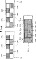
Es gibt verschiedene Möglichkeiten der Anzeige der beiden Bilder auf der Anzeigeeinrichtung. Dies kann zum einen an der Art der verwendeten Anzeigeeinrichtung und/oder auch an der Aufbereitung der Bilder zu deren Anzeige. Es gibt z.B. Anzeigeeinrichtungen, deren Bildpunkte (Pixel) in der Art der Felder eines Schachbretts angeordnet sind. Es gibt auch Anzeigeeinrichtungen, deren „Bildpunkte“ streifenförmig verlaufen. Es gibt Anzeigeeinrichtungen, bei denen die Polarisationsachse einzelner Bildpunkte fest vorgegeben ist. Bei anderen Anzeigeeinrichtungen kann die Polarisationsachse sämtlicher Felder in beliebiger Weise eingestellt werden. Anzeigeeinrichtungen bei denen die Polarisationsachse einzelner Bildpunkte fest vorgegeben ist, können z.B. schachbrettmusterartig mit hellen und dunklen Feldern aufgebaut sein, wobei die den hellen Feldern des Schachbretts entsprechenden Bildpunkte eine Polarisationsachse aufweisen und die den dunklen Feldern entsprechenden Bildpunkte eine andere Polarisationsachse. Bei Anzeigeeinrichtungen mit bildpunktuell einstellbarer Polarisationsachse ist es dann wiederum möglich, diese mit Hilfe einer geeigneten Software in der Art von Anzeigeeinrichtungen mit fest vorgegebenen Polarisationsachse zu betreiben, indem vorbestimmten Bildpunkten stets dieselbe Polarisationsachse zugewiesen wird. There are various ways of displaying the two images on the display device. This can be due to the type of display used and / or the preparation of the images for their display. There are e.g. Display devices whose pixels are arranged in the manner of the fields of a chessboard. There are also display devices whose "pixels" are striped. There are display devices in which the polarization axis of individual pixels is fixed. In other display devices, the polarization axis of all fields can be adjusted in any way. Display devices in which the polarization axis of individual pixels is fixed, can be used e.g. be constructed like a checkerboard pattern with light and dark fields, wherein the bright fields of the chess board corresponding pixels have a polarization axis and the dark fields corresponding pixels have a different polarization axis. In display devices with pixel-adjustable polarization axis, it is then possible to operate them with the aid of suitable software in the form of display devices with a fixed predetermined polarization axis by predetermined pixels is always assigned the same polarization axis.
Unter Bildpunkten mit einer definierten Polarisationsachse sind solche Bildpunkte zu verstehen, welche alle zumindest 80 %, vorzugsweise zumindest 90 %, weiter vorzugsweise mindestens 95 % linear polarisierte Strahlung erzeugen, wobei der elektrische Vektor der Strahlung der Bildpunkte in einer zur Polarisationsebene parallelen Ebene enthalten ist. Pixels with a defined polarization axis are to be understood as those pixels which all produce at least 80%, preferably at least 90%, more preferably at least 95% linearly polarized radiation, the electric vector of the radiation of the pixels being contained in a plane parallel to the plane of polarization.
Basierend auf dieser Erkenntnis kann die Anzeigeeinrichtung so eingerichtet sein, dass das angezeigte erste Bild aus ersten in der Art der Felder einer einzigen der Farben eines Schachbrettmusters angeordneten Bildpunkten besteht und dass das angezeigte zweite Bild aus zweiten in der Art der Felder der anderen Farbe des Schachbrettmusters angeordneten Bildpunkten besteht. Diese Anzeige eignet sich besonders für den Fall, wenn das menschliche Auge beim Betrachten die einzelnen Pixel nicht getrennt nebeneinander wahrnimmt, wie z.B. bei einem Computer- oder Fernsehbildschirm. Based on this insight, the display device may be arranged such that the displayed first image consists of first pixels arranged in the manner of the fields of a single of the colors of a checkerboard pattern, and the displayed second image of second in the manner of the fields of the other color of the checkerboard pattern arranged pixels exists. This display is particularly suitable for the case when the human eye when viewing the individual pixels not separately perceived side by side, such as. on a computer or TV screen.
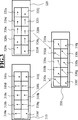
Die Anzeigeeinrichtung kann aber auch derart eingerichtet sein, dass das erste Bild aus in der Art aller Felder eines Schachbrettmusters angeordneten Bildpunkten besteht und dass das zweite Bild aus denselben Bildpunkten besteht und dass die jeweiligen angezeigten Bildpunkte die Information des entsprechenden Bildpunktes des ersten Bildes und die Information des entsprechenden Bildpunktes des zweiten Bildes enthält, wobei die Polarisationsrichtung der Vektoraddition der die Intensität berücksichtigenden Polarisationsrichtungsvektoren der entsprechenden Bildpunkte des ersten Bildes und des zweiten Bildes entspricht. However, the display device can also be set up such that the first image consists of pixels arranged in the manner of all fields of a checkerboard pattern and that the second image consists of the same pixels and that the respective pixels displayed are the information of the corresponding pixel of the first image and the information of the corresponding pixel of the second image, wherein the polarization direction of the vector addition corresponds to the intensity-taking polarization direction vectors of the corresponding pixels of the first image and the second image.
Grundsätzlich ist es möglich zur erfindungsgemäßen Demonstration in jeglicher Art linear polarisierte Bilder einander überlagert anzuzeigen soweit sich deren Polarisationsrichtungen unterscheiden. In besonders einfacher Weise lässt der polarisierende Effekt von polarisierenden Brillengläsern zeigen, wenn die erste Polarisationsrichtung senkrecht zu der zweiten Polarisationsrichtung ist. Damit lässt sich durch entsprechende Positionierung des Probanden und bekannter Orientierung der Polarisationsachse seiner polarisierender Brille festlegen, welches der beiden Bilder er wahrnimmt und welches nicht. In principle, it is possible for the demonstration according to the invention in any way linearly polarized images superimposed to show as far as their polarization directions differ. The polarizing effect of polarizing spectacle lenses is particularly simple show when the first polarization direction is perpendicular to the second polarization direction. This can be determined by appropriate positioning of the subject and known orientation of the polarization axis of his polarizing glasses, which of the two images he perceives and which not.
Es ist grundsätzlich möglich, die Anzeigeeinrichtung derart auszubilden, dass ein Betrachter einen dreidimensionalen Seheindruck erhält. Die Anzeigeeinrichtung muss dann Bereiche aufweisen, die ausschließlich für das linke Auge des Betrachters sichtbar sind und Bereiche, die ausschließlich für das rechte Auge des Betrachters sichtbar sind. Jeder der Bereiche für sich muss dann zum Anzeigen eines ersten Bildes mit in der ersten Polarisationsrichtung polarisiertem Licht und eines zweiten Bildes mit in der zweiten Polarisationsrichtung polarisiertem Licht in überlagerter Darstellung ausgebildet sein, so dass das Motiv des ersten Bildes und das Motiv des zweiten Bildes formidentisch zusammenfallen. Der dreidimensionale Seheindruck wird dadurch erzeugt, dass die Darstellung des Motivs des ersten Bereichs und des Motivs des zweiten Bereichs nicht formidentisch zusammenfallen. It is basically possible to design the display device such that a viewer receives a three-dimensional visual impression. The display device must then have areas that are visible only to the left eye of the viewer and areas that are visible only to the right eye of the viewer. Each of the areas per se must then be designed to display a first image with polarized light in the first polarization direction and a second image polarized in the second polarization light in superimposed representation, so that the motif of the first image and the motif of the second image form identical coincide. The three-dimensional visual impression is produced by the fact that the representation of the motif of the first region and of the motif of the second region do not coincide in a shape identical to one another.
Auf dem auf der in dem optischen Strahlengang zu den Augen des Probanden weisenden Seite der Anzeigeeinrichtung ist zu diesem Zweck eine Optikbaugruppe angeordnet, die das von einer ersten Gruppe ausgewählter Bereiche der Anzeigeeinrichtung dem optischen Strahlengang zugeführte Licht von dem Licht trennt, das dem Strahlengang von einer zweiten Gruppe ausgewählter Bereiche der Anzeigeeinrichtung zugeführt ist, um dem linken Auge des Probanden das Licht aus der ersten Gruppe ausgewählter Bereiche der Anzeigeeinrichtung zuzuführen und das Licht aus der zweiten Gruppe ausgewählter Bereiche der Anzeigeeinrichtung zu dem rechten Auge des Probanden zu leiten. On the side of the display device facing in the optical beam path to the eyes of the subject, an optical assembly is arranged for this purpose, which separates the light supplied from a first group of selected areas of the display device to the optical beam path from the light emitted from the beam path second group of selected areas of the display device is supplied to the left eye of the subject, the light from the first group of selected areas of the display device and to direct the light from the second group of selected areas of the display device to the right eye of the subject.
Die Optikbaugruppe für das Trennen des Lichts der ersten und zweiten Gruppe ausgewählter Bereiche der Anzeigeeinrichtung mit einem als Parallaxebarriere wirkenden Blendensystem auszubilden. Hierfür kann das Blendensystem z.B. als eine Maske mit abwechselnd lichtdurchlässigen und lichtundurchlässigen Bereichen ausgebildet sein. Form the optics assembly for separating the light of the first and second groups of selected regions of the display device with a diaphragm system acting as a parallax barrier. For this purpose, the diaphragm system can e.g. be formed as a mask with alternating translucent and opaque areas.
Die abwechselnd lichtdurchlässigen und lichtundurchlässigen Bereiche der Maske können eine Schachbrettform oder eine Streifenform haben. Zweckmäßigerweise sind die Schachbrettform der Bildpunkte und die Schachbrett- oder Streifenform der Maske parallel zueinander angeordnet bzw. ausgerichtet. The alternately translucent and opaque areas of the mask may have a checkerboard shape or a stripe shape. The chessboard shape of the pixels and the checkerboard or stripe shape of the mask are expediently arranged or aligned parallel to one another.
Im allgemeinen Teil der Beschreibungseinleitung wurde darauf hingewiesen, dass auch phototrope Brillengläser zu den polarisierenden Brillengläsern zählen. Um die Wirkungsweise derartiger Brillengläser zu demonstrieren, sieht die Erfindung fakultativ eine Lichtquelle zum Aktivieren der phototropen Brillengläsern vor. In the general part of the introduction to the description, it has been pointed out that photochromic spectacle lenses also belong to the polarizing spectacle lenses. To demonstrate the operation of such spectacle lenses, the invention optionally provides a light source for activating the photochromic spectacle lenses.
Das erfindungsgemäße Verfahren zur Demonstration des Seheindrucks für einen Träger einer Brille mit polarisierenden Brillengläsern, umfasst die folgenden Schritte:
- a) Bereitstellen eines ersten Bildes mit einem Motiv und einer zugehörigen ersten Polarisationsrichtung
- b) Bereitstellen eines zweiten Bildes mit demselben Motiv und einer zugehörigen zweiten von der ersten Polarisationsrichtung verschiedenen Polarisationsrichtung
- c) Anzeigen des ersten Bildes mit in der ersten Polarisationsrichtung polarisiertem Licht und des zweiten Bildes mit in der zweiten Polarisationsrichtung polarisiertem Licht in überlagerter Darstellung, so dass das Motiv des ersten Bildes und das Motiv des zweiten Bildes formidentisch zusammenfallen.
- a) providing a first image with a motif and an associated first polarization direction
- b) providing a second image having the same motif and an associated second polarization direction different from the first polarization direction
- c) displaying the first image with light polarized in the first polarization direction and the second image with polarized light in the second polarization direction in superimposed representation, so that the motif of the first image and the motif of the second image coincide in identical shape.
Als erstes Bild kann wie oben zur erfindungsgemäßen Vorrichtung bereits ausgeführt wurde eine fotographische Aufnahme einer Kamera mit vorgeschaltetem Polarisationsfilter mit einer ersten Polarisationsachse verwendet werden. Alternativ oder zusätzlich kann auch als zweites Bild eine fotographische Aufnahme einer Kamera mit vorgeschaltetem Polarisationsfilter mit einer zweiten von der ersten Polarisationsachse verschiedenen Polarisationsachse verwendet werden. Diese können z.B. zusammen mit der Information über die Richtung der Polarisationsachse des verwendeten Filters als der jeweiligen zugehörigen Polarisationsrichtung abgespeichert werden. Letzteres ist jedoch nicht zwingend erforderlich. Die bereitgestellte jeweilige zugehörige Polarisationsrichtung kann auch jede andere beliebige Polarisationsrichtung sein. Zur Erzeugung einer möglichst realistischen Anzeige wird jedoch die Richtung der Polarisationsachse und der Polarisationsrichtung zusammenfallen (Die gleiche Orientierung von Aufnahmebild und Anzeigebild wird natürlich vorausgesetzt). As a first image, as already mentioned above for the device according to the invention, a photographic image of a camera with an upstream polarization filter having a first polarization axis can be used. Alternatively or additionally, a photographic image of a camera with an upstream polarization filter with a second polarization axis different from the first polarization axis can also be used as the second image. These may e.g. stored together with the information about the direction of the polarization axis of the filter used as the respective associated polarization direction. The latter is not mandatory. The respective associated polarization direction provided can also be any other polarization direction. However, the direction of the polarization axis and the polarization direction will coincide to produce the most realistic display possible (the same orientation of the recorded image and the display image is of course assumed).
Bei dem erfindungsgemäßen Verfahren ist es von Vorteil, wenn sich das erste Bild und das zweite Bild in wenigstens einer optischen Eigenschaft, insbesondere in wenigstens einer der optischen Eigenschaften aus der Gruppe Kontrast, Helligkeit, Sättigung und Farbton unterscheiden. Die Gründe wurden oben zu der Beschreibung der erfindungsgemäßen Vorrichtung bereits dargelegt. In the method according to the invention, it is advantageous if the first image and the second image differ in at least one optical property, in particular in at least one of the optical properties from the group contrast, brightness, saturation and hue. The reasons have already been set out above for the description of the device according to the invention.
Es ist einerseits möglich, dass das angezeigte erste Bild aus ersten in der Art der Felder einer einzigen der Farben eines Schachbrettmusters angeordneten Bildpunkten besteht und dass das angezeigte zweite Bild aus zweiten in der Art der Felder der anderen Farbe des Schachbrettmusters angeordneten Bildpunkten besteht und es ist weiter möglich, dass das erste Bild aus in der Art der Felder eines Schachbrettmusters angeordneten Bildpunkten besteht und dass das zweite Bild aus denselben Bildpunkten besteht und dass die jeweiligen angezeigten Bildpunkte die Information des entsprechenden Bildpunktes des ersten Bildes und die Information des entsprechenden Bildpunktes des zweiten Bildes enthält, wobei die Polarisationsrichtung der Vektoraddition der die Intensität berücksichtigenden Polarisationsrichtungsvektoren der entsprechenden Bildpunkte des ersten Bildes und des zweiten Bildes entspricht. It is possible, on the one hand, for the displayed first image to be first in the manner of the fields of a single one of the colors of a checkerboard pattern arranged pixels and that the displayed second image consists of second arranged in the nature of the fields of the other color of the checkerboard pattern pixels and it is further possible that the first image consists of arranged in the nature of the fields of a checkerboard pattern pixels and that the second image consists of the same pixels, and that the respective displayed pixels contain the information of the corresponding pixel of the first image and the information of the corresponding pixel of the second image, the polarization direction of the vector addition corresponding to the intensity-taking polarization direction vectors of the corresponding pixels of the first image and the second image ,
Da eine herkömmliche Sonnenbrille polarisierende Gläser besitzt, deren Polarisationsachse um nicht mehr als +/–5° von der Vertikalen abweichen, ist es günstig, wenn die erste Polarisationsrichtung horizontal und die zweite Polarisationsrichtung vertikal ausgerichtet wird. Die Polarisationsrichtung eines der beiden Bilder entspricht demzufolge der Richtung der Polarisationsachse der Brillengläser und die Polarisationsrichtung des anderen der beiden Bilder steht senkrecht auf dieser Polarisationsachse. Demzufolge nimmt der Brillenträger mit polarisierender Brille nur das eine der Bilder wahr, während er ohne polarisierende Brille beide Bilder in Überlagerung sieht. Bei Betrachtung der Bilderzeugungseinrichtung ohne polarisierende Brillengläser ist die Überlagerung aller polarisierten Bilder sichtbar, da das bloße Auge Licht mit verschiedenen Polarisationsrichtungen nicht unterscheiden kann. Since conventional sunglasses have polarizing lenses whose polarization axes do not deviate more than +/- 5 ° from the vertical, it is favorable if the first polarization direction is oriented horizontally and the second polarization direction is aligned vertically. The polarization direction of one of the two images therefore corresponds to the direction of the polarization axis of the spectacle lenses and the polarization direction of the other of the two images is perpendicular to this polarization axis. As a result, the spectacle wearer with polarized glasses only perceives one of the images, while he sees both images in superposition without polarizing glasses. When viewing the imaging device without polarizing lenses, the superposition of all polarized images is visible because the naked eye can not distinguish light with different polarization directions.
Das Verfahren nach der Erfindung kann folgenden weiteren Verfahrensschritt umfassen:
- d) Positionieren eines Probanden zum Betrachten der angezeigten Bilder in überlagerter Darstellung wahlweise mit dem bloßen Auge und/oder durch eine Brille mit nicht-polarisierenden Brillengläsern und/oder durch die Brille mit den polarisierenden Brillengläsern.
- d) positioning a subject for viewing the displayed images in a superimposed representation optionally with the naked eye and / or by glasses with non-polarizing lenses and / or by the glasses with the polarizing lenses.
Damit werden dem Probanden die unterschiedlichen Seheindrücke mit dem bloßen Auge, durch eine Brille mit nicht-polarisierenden Brillengläsern und durch eine Brille mit den polarisierenden Brillengläsern verdeutlicht und der Proband wird die Vorzüge von polarisierenden Brillengläsern erkennen. Thus, the subject's different visual impressions with the naked eye, by glasses with non-polarizing lenses and glasses with the polarizing lenses are clarified and the subject will recognize the benefits of polarizing lenses.
In diesem Zusammenhang kann dem Probanden auf Nachfrage auch die Funktionsweise und die Wirkung phototroper Brillengläser nahegebracht werden. Es ist daher vorgesehen bei Bedarf eine die phototropen Brillengläser aktivierende Lichtquelle einzuschalten. In this context, the subject on demand, the functioning and the effect of photochromic lenses can be taught. It is therefore intended if necessary to turn on a photochromic lenses activating the light source.
Die Lichtquelle kann z.B. eine UV-Lampe sein. Mittels einer derartigen UV-Lampe, welche geeignet ist, phototrope Brillengläser zu aktivieren, kann z.B. eine phototrope polarisierende Brille für 60 Sekunden mit ultraviolettem Licht bestrahlt werden. Die so bestrahlte phototrope polarisierende Brille zeigt nach Bestrahlung polarisierende Eigenschaften. Eine Testperson kann dann die Qualität dieser Brille überprüfen. The light source may e.g. be a UV lamp. By means of such a UV lamp, which is suitable for activating photochromic lenses, can e.g. a photochromic polarizing glasses are irradiated for 60 seconds with ultraviolet light. The thus irradiated photochromic polarizing glasses show polarizing properties after irradiation. A test subject can then check the quality of these glasses.
Unter Umständen ist es sinnvoll, dass die zur Aktivierung geeignete Lampe zumindest ab dem Positionieren eines Probanden dauerhaft leuchtet, sodass eine konstante Aktivierung der phototropen polarisierenden Brillengläser erfolgt. Under certain circumstances, it makes sense for the lamp suitable for activation to be permanently lit at least from the position of a subject, so that a constant activation of the photochromic polarizing spectacle lenses takes place.
Die Erfindung wird nachfolgend anhand der Zeichnung näher beschrieben. Gleiche oder funktionsgleiche Komponenten sind in den Figuren mit identischen Bezugszeichen versehen. Es zeigen: The invention will be described in more detail with reference to the drawing. The same or functionally identical components are provided in the figures with identical reference numerals. Show it:
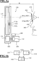
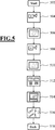
a) Aufbau der Vorrichtung
b) Bildüberlagerung mit der Vorrichtung
a) Construction of the device
b) Image overlay with the device
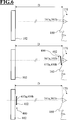
a) Brille mit Fassung und Brillenglashorizontale
b) Polarisationswirkung eines polarisierenden Brillenglases in perspektivischer Darstellung
c) polarisierende Brillengläser mit unterschiedlicher Polarisationsachse
d) polarisierende Brille mit vertikal polarisierenden Brillengläsern
a) Glasses with frame and lens horizontal
b) Polarization effect of a polarizing spectacle lens in a perspective view
c) polarizing spectacle lenses with different polarization axis
d) polarizing glasses with vertically polarizing lenses
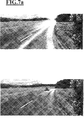
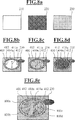
a) Straßenverkehrsmotiv:
Bild oben: Aufnahme mit Polarisationsfilter mit horizontaler Polarisationsachse
Bild unten: Aufnahme mit Polarisationsfilter mit vertikaler Polarisationsachse
b) Strandmotiv:
Bild oben: Aufnahme mit Polarisationsfilter mit horizontaler Polarisationsachse
Bild unten: Aufnahme mit Polarisationsfilter mit vertikaler Polarisationsachse
a) Traffic motive:
Picture above: Image with polarization filter with horizontal polarization axis
Picture below: Image with polarization filter with vertical polarization axis
b) Beach theme:
Picture above: Image with polarization filter with horizontal polarization axis
Picture below: Image with polarization filter with vertical polarization axis
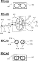
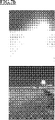
a) zwei polarisierende Bilder und überlagertes Bild
b) sichtbares Bild bei Betrachtung des überlagerten Bildes nach a) mit einem polarisierenden Brillenglas mit vertikaler Polarisationsachse
c) sichtbares Bild bei Betrachtung des überlagerten Bildes nach a) mit einem polarisierenden Brillenglas mit 45° geneigter Polarisationsachse
d) sichtbares Bild bei Betrachtung des überlagerten Bildes nach a) mit einem polarisierenden Brillenglas mit horizontaler Polarisationsachse
e) sichtbares Bild bei Betrachtung des überlagerten Bildes nach a) mit einem polarisierenden Brillenglas mit nicht einheitlicher Polarisationsachse
a) two polarizing images and superimposed image
b) visible image when viewing the superimposed image according to a) with a polarizing spectacle lens with vertical polarization axis
c) visible image when viewing the superimposed image according to a) with a polarizing spectacle lens with 45 ° inclined polarization axis
d) visible image when viewing the superimposed image according to a) with a polarizing spectacle lens with horizontal polarization axis
e) visible image when viewing the superimposed image according to a) with a polarizing spectacle lens with non-uniform polarization axis
Die
Die Schemazeichnung der
Das Display
Jeder Bildpunkt
So kann die jeweilige Polarisationsebene der Bildpunkte
Die Definition der Polarisationsebene von Bildpunkten
Es gibt Displays, bei denen nur eine Wahl zwischen diskreten, fest vorgegebenen Polarisationsebenen besteht. Bei anderen Displays kann die Polarisationsebene der Bildpunkte
In dem Speicher
Mit Hilfe des Displays
Eine mögliche Anordnung der Bildpunkte zur Anzeige des ersten Bildes
Die
Die Überlagerung der beiden Bilder
Die
Ferner sind in der
Polarisierende Brillengläser
Die
Ausgangspunkt ist zunächst die Suche nach einem geeigneten Motiv anhand dessen dem Träger die Wirkung einer polarisierenden Brille verdeutlicht werden soll (nicht in
The starting point is first of all the search for a suitable motif by means of which the wearer should be made aware of the effect of polarizing glasses (not in
Von einem für geeignet befundenen Motiv wird in einem ersten Schritt
In einem nachfolgenden Schritt
In dem nachfolgenden Schritt
Die
Bei unterschiedlicher definierter erster und zweiter Polarisationsebene von Bildpunkten
Wenn sich zwischen den Augen
Wenn zwischen den Augen
Das überlagerte polarisierte Bild
In diesem ersten Ausführungsbeispiel ist es unerheblich, ob die polarisierenden Brillengläser
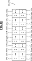
In einem weiteren graphisch nicht dargestellten Ausführungsbeispiel werden zwei formidentische Bilder mit einer Intensitätsverteilung B1(x, y) und B2(x, y) im Computer erzeugt. x und y sind dabei der Index der Spalte bzw. Zeile am Display, der Funktionswert B1 bzw. B2 an einem solchen Punkt x, y gibt die Helligkeit eines Bildpunktes an, bzw. bei farbiger Darstellung die Helligkeit der jeweiligen Farbe Rot, Grün, und Blau. Das Bild B1 unterscheidet sich nur in den optischen Eigenschaften von Bild B2. Insbesondere zeigt das Bild B1 verminderte Reflexe, verminderte Blendungen oder ähnliches. Mathematisch gilt für jeden Punkt x, y, dass B2(x, y) >= B1(x, y) ist. In a further embodiment, which is not illustrated graphically, two form-identical images with an intensity distribution B1 (x, y) and B2 (x, y) are generated in the computer. x and y are the index of the column or line on the display, the function value B1 or B2 at such a point x, y indicates the brightness of a pixel, or in color representation, the brightness of the respective color red, green, and Blue. The picture B1 differs only in the optical properties of picture B2. In particular, image B1 shows diminished reflections, diminished glare or the like. Mathematically, for every point x, y, it holds that B2 (x, y)> = B1 (x, y).
Wird nun ein erstes polarisiertes Bild
Wenn zwischen den Augen
Wenn sich zwischen den Augen
Bei polarisierenden Brillengläsern
Bei gänzlich von 90° abweichender Polarisationsachse
Es ist demnach mit der vorliegenden Erfindung möglich, verschiedene Mängel an polarisierenden Brillengläsern
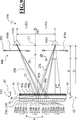
Die
Das in der
Damit ergibt sich für jedes Auge
Das Display
Die Maske
Die Bereiche
Mit den für das Licht des Displays
Die günstige Verschiebung der Maske
Dabei ist S die Ablage des Zentrums der senkrechten Projektion der Pupillendistanz PD in der der Ebene
BezugszeichenlisteLIST OF REFERENCE NUMBERS
- αα
- Sehwinkel viewing angle
- ββ
- Winkel angle
- B1B1
- Intensitätsverteilung intensity distribution
- B2B2
- Intensitätsverteilungintensity distribution
- DD
- Abstand des Probanden vom Display Distance of the subject from the display
- BMd B Md
- Breite der durchlässigen Bereiche der Maske Width of the permeable areas of the mask
- BMu B Mu
- Breite der lichtundurchlässigen Bereiche der Maske Width of the opaque areas of the mask
- g G
- Abstand des Probanden von der Lichtdurchtrittsebene Distance of the subject from the light passage level
- γγ
- Winkel angle
- PD PD
- Pupillendistanz pupillary distance
- S S
- Ablage filing
- V V
- Verschiebung shift
- x x
- Richtung, Index Direction, index
- y y
- Richtung, Index Direction, index
- z z
- Richtung, Abstand Direction, distance
- 25a 25a
- Licht für das rechte Auge Light for the right eye
- 25b 25b
- Licht für das linke Auge Light for the left eye
- 27 27
- Punkt Point
- 29 29
- Gerade Just
- 31 31
- Punkt Point
- 37 37
- Maske mask
- 38 38
- Trägerelement support element
- 41 41
- Lichtdurchtrittsebene Light transmission level
- 42 42
- Ebene level
- 43 43
- Doppelpfeil double arrow
- 90a 90a
- undurchlässiger Bereich impermeable area
- 90b 90b
- undurchlässiger Bereich impermeable area
- 90c 90c
- undurchlässiger Bereich impermeable area
- ......
- 92a 92a
- durchlässiger Bereich permeable area
- 92b 92b
- durchlässiger Bereich permeable area
- 92c 92c
- durchlässiger Bereich permeable area
- ......
- 100 100
- Vorrichtung contraption
- 102 102
- Bilderzeugungseinrichtung Imaging device
- 110 110
- Display display
- 112a 112a
- Bildpunkt pixel
- 112b 112b
- Bildpunkt pixel
- 112c 112c
- Bildpunkt pixel
- 114 114
- erstes Bild first picture
- 116 116
- zweites Bild second picture
- 118 118
- Anzeigebild display image
- 120 120
- Treibergruppe driver group
- 122a 122a
- Motiv des ersten Bildes Motif of the first picture
- 122b 122b
- Motiv des zweiten Bildes Motif of the second picture
- 122 122
- Motiv motive
- 140 140
- Lichtquelle zum Aktivieren von phototropen Brillengläsern Light source for activating photochromic lenses
- 150 150
- Rechnereinheit, Computer Computer unit, computer
- 152 152
- Speicher Storage
- 160 160
- Nase nose
- 161a 161a
- rechtes Auge right eye
- 161b 161b
- linkes Auge left eye
- 170 170
- Proband Family
- 210 210
- erstes polarisiertes Bild first polarized picture
- 210a 210a
- Bildpunkt mit einer ersten definierten Polarisationsachse Pixel with a first defined polarization axis
- 210b 210b
- Bildpunkt mit einer ersten definierten Polarisationsachse Pixel with a first defined polarization axis
- 210c 210c
- Bildpunkt mit einer ersten definierten Polarisationsachse Pixel with a first defined polarization axis
- ......
- 220 220
- zweites polarisiertes Bild second polarized picture
- 220a 220a
- Bildpunkt mit einer zweiten definierten Polarisationsachse Pixel with a second defined polarization axis
- 220b 220b
- Bildpunkt mit einer zweiten definierten Polarisationsachse Pixel with a second defined polarization axis
- 220c 220c
- Bildpunkt mit einer zweiten definierten Polarisationsachse Pixel with a second defined polarization axis
- ......
- 230 230
- überlagertes polarisiertes Bild superimposed polarized image
- 310 310
- erstes polarisiertes Bild first polarized picture
- 310a 310a
- Bildpunkt mit einer ersten definierten Polarisationsachse Pixel with a first defined polarization axis
- 310b 310b
- Bildpunkt mit einer ersten definierten Polarisationsachse Pixel with a first defined polarization axis
- 310c 310c
- Bildpunkt mit einer ersten definierten Polarisationsachse Pixel with a first defined polarization axis
- ... ...
- 320 320
- zweites polarisiertes Bild second polarized picture
- 320a 320a
- Bildpunkt mit einer zweiten definierten Polarisationsachse Pixel with a second defined polarization axis
- 320b 320b
- Bildpunkt mit einer zweiten definierten Polarisationsachse Pixel with a second defined polarization axis
- 320c 320c
- Bildpunkt mit einer zweiten definierten Polarisationsachse Pixel with a second defined polarization axis
- ......
- 330 330
- überlagertes polarisiertes Bild superimposed polarized image
- 330a 330a
- Bildpunkt mit durch Vektoraddition ermittelter Polarisationsachse Pixel with polarization axis determined by vector addition
- 330b 330b
- Bildpunkt mit durch Vektoraddition ermittelter Polarisationsachse Pixel with polarization axis determined by vector addition
- 330c 330c
- Bildpunkt mit durch Vektoraddition ermittelter Polarisationsachse Pixel with polarization axis determined by vector addition
- ......
- 400 400
- Brille glasses
- 402 402
- Fassung version
- 404 404
- Fassungshorizontale Horizontal version
- 410 410
- polarisierendes Brillenglas polarizing spectacle lens
- 410a 410a
- polarisierendes Brillenglas für das rechte Auge polarizing lens for the right eye
- 410b 410b
- polarisierendes Brillenglas für das linke Auge polarizing lens for the left eye
- 411 411
- Polarisationsachse polarization axis
- 411a 411a
- Polarisationsachse polarization axis
- 411b 411b
- Polarisationsachse polarization axis
- 412 412
- Markierungen marks
- 412a 412a
- Markierungen marks
- 412b 412b
- Markierungen marks
- 413 413
- Polarisationsebene plane of polarization
- 414 414
- Transmissionsebene transmission level
- 416 416
- auf Brillenglas auftreffendes Licht light striking spectacle lenses
- 416a 416a
- Polarisationsrichtung polarization direction
- 416b 416b
- Polarisationsrichtung polarization direction
- 417 417
- Brillenglas transmittierendes Licht Spectacle lens transmissive light
- 417a 417a
- Polarisationsrichtung polarization direction
- 418 418
- Ausbreitungsrichtung propagation direction
- 420 420
- polarisierende Brillengläser in einer Fassung polarizing lenses in a socket
- 502 502
- Verfahrensschritt step
- 504 504
- Verfahrensschritt step
- 506 506
- Verfahrensschritt step
- 508 508
- Verfahrensschritt step
- 510 510
- Verfahrensschritt step
- 512 512
- Verfahrensschritt step
- 514 514
- Verfahrensschritt step
- 516 516
- Verfahrensschritt step
- 518 518
- Verfahrensschritt step
- 800a 800a
- Zone mit geringem Polarisationsgrad Zone with low degree of polarization
- 800b 800b
- Zone mit geringem Polarisationsgrad Zone with low degree of polarization
- 800c 800c
- Zone mit geringem Polarisationsgrad Zone with low degree of polarization
- 800d 800d
- Zone mit geringem Polarisationsgrad Zone with low degree of polarization
- 1210 1210
- erstes polarisiertes Bild für das rechte Auge first polarized image for the right eye
- 1210a1210a
- Bildpunkt mit einer ersten definierten Polarisationsachse Pixel with a first defined polarization axis
- 1210b1210b
- Bildpunkt mit einer ersten definierten Polarisationsachse Pixel with a first defined polarization axis
- 1210c1210c
- Bildpunkt mit einer ersten definierten Polarisationsachse Pixel with a first defined polarization axis
- ......
- 1220 1220
- zweites polarisiertes Bild für das linke Auge second polarized image for the left eye
- 1220a1220a
- Bildpunkt mit einer zweiten definierten Polarisationsachse Pixel with a second defined polarization axis
- 1220b1220b
- Bildpunkt mit einer zweiten definierten Polarisationsachse Pixel with a second defined polarization axis
- 1220c1220c
- Bildpunkt mit einer zweiten definierten Polarisationsachse Pixel with a second defined polarization axis
- ......
- 1230 1230
- überlagertes polarisiertes Bild superimposed polarized image
ZITATE ENTHALTEN IN DER BESCHREIBUNG QUOTES INCLUDE IN THE DESCRIPTION
Diese Liste der vom Anmelder aufgeführten Dokumente wurde automatisiert erzeugt und ist ausschließlich zur besseren Information des Lesers aufgenommen. Die Liste ist nicht Bestandteil der deutschen Patent- bzw. Gebrauchsmusteranmeldung. Das DPMA übernimmt keinerlei Haftung für etwaige Fehler oder Auslassungen.This list of the documents listed by the applicant has been generated automatically and is included solely for the better information of the reader. The list is not part of the German patent or utility model application. The DPMA assumes no liability for any errors or omissions.
Zitierte PatentliteraturCited patent literature
- US 747235 [0010] US 747235 [0010]
- EP 0512443 A1 [0017] EP 0512443 A1 [0017]
- EP 0595023 A1 [0018, 0019] EP 0595023 A1 [0018, 0019]
- DE 19947775 A1 [0019] DE 19947775 A1 [0019]
- DE 10007020 A1 [0020] DE 10007020 A1 [0020]
- US 2006/0203338 A1 [0022, 0026] US 2006/0203338 A1 [0022, 0026]
Zitierte Nicht-PatentliteraturCited non-patent literature
- DIN EN ISO 13666 (1998) [0004] DIN EN ISO 13666 (1998) [0004]
- DIN EN ISO 8980-3:2004 [0004] DIN EN ISO 8980-3: 2004 [0004]
- DIN EN 1836:2005 + A1:2007 [0004] DIN EN 1836: 2005 + A1: 2007 [0004]
- DIN EN 1836:2005 + A1:2007 [0009] DIN EN 1836: 2005 + A1: 2007 [0009]
- DIN EN 1836:2005 + A1:2007 (D) [0010] DIN EN 1836: 2005 + A1: 2007 (D) [0010]
- DIN EN 1836 [0011] DIN EN 1836 [0011]
- DIN EN ISO 13666 [0011] DIN EN ISO 13666 [0011]
- DIN EN 1836:2005 + A1:2007 (D) [0012] DIN EN 1836: 2005 + A1: 2007 (D) [0012]
- DIN EN ISO 8980-3:2004 [0012] DIN EN ISO 8980-3: 2004 [0012]
Claims (15)
Priority Applications (6)
| Application Number | Priority Date | Filing Date | Title |
|---|---|---|---|
| DE102012217841.4A DE102012217841A1 (en) | 2012-09-28 | 2012-09-28 | Apparatus and method for demonstrating the visual impression of a wearer of spectacles with polarizing spectacle lenses |
| PCT/EP2013/069711 WO2014048873A1 (en) | 2012-09-28 | 2013-09-23 | Device and method for demonstrating the visual impression for a wearer of a pair of spectacles with polarizing spectacle lenses |
| EP13770657.8A EP2901208B1 (en) | 2012-09-28 | 2013-09-23 | Device and method for demonstrating the visual impression for a wearer of a pair of spectacles with polarizing spectacle lenses |
| ES13770657.8T ES2605634T3 (en) | 2012-09-28 | 2013-09-23 | Device and procedure for demonstrating visual impression for a wearer of glasses with polarizing crystals |
| BR112015006899-5A BR112015006899B1 (en) | 2012-09-28 | 2013-09-23 | device and process for demonstrating the visual impression of a spectacle wearer with polarizing spectacle lenses |
| US14/672,197 US10325521B2 (en) | 2012-09-28 | 2015-03-29 | Apparatus and method for demonstrating the visual impression for a wearer of spectacles having polarizing spectacle lenses |
Applications Claiming Priority (1)
| Application Number | Priority Date | Filing Date | Title |
|---|---|---|---|
| DE102012217841.4A DE102012217841A1 (en) | 2012-09-28 | 2012-09-28 | Apparatus and method for demonstrating the visual impression of a wearer of spectacles with polarizing spectacle lenses |
Publications (1)
| Publication Number | Publication Date |
|---|---|
| DE102012217841A1 true DE102012217841A1 (en) | 2014-04-03 |
Family
ID=50276245
Family Applications (1)
| Application Number | Title | Priority Date | Filing Date |
|---|---|---|---|
| DE102012217841.4A Pending DE102012217841A1 (en) | 2012-09-28 | 2012-09-28 | Apparatus and method for demonstrating the visual impression of a wearer of spectacles with polarizing spectacle lenses |
Country Status (6)
| Country | Link |
|---|---|
| US (1) | US10325521B2 (en) |
| EP (1) | EP2901208B1 (en) |
| BR (1) | BR112015006899B1 (en) |
| DE (1) | DE102012217841A1 (en) |
| ES (1) | ES2605634T3 (en) |
| WO (1) | WO2014048873A1 (en) |
Cited By (2)
| Publication number | Priority date | Publication date | Assignee | Title |
|---|---|---|---|---|
| CN104739362A (en) * | 2015-02-13 | 2015-07-01 | 富阳学院 | Remote control adjustable visual acuity chart |
| CN111724668A (en) * | 2020-07-24 | 2020-09-29 | 长春理工大学 | Optical axis alignment method and device for multi-light source hybrid solar simulation device |
Families Citing this family (5)
| Publication number | Priority date | Publication date | Assignee | Title |
|---|---|---|---|---|
| US20160352974A1 (en) * | 2015-05-27 | 2016-12-01 | Allan N. Hytowitz | Using Comparative Pixel and Luminance Adjustment for Creating a Varying Acuity Perception |
| US9671626B2 (en) * | 2016-05-19 | 2017-06-06 | Maximilian Ralph Peter von und zu Liechtenstein | Apparatus and method for augmenting human vision by means of adaptive polarization filter grids |
| CN109118919B (en) * | 2018-09-17 | 2024-10-15 | 安徽新华学院 | Pixel jigsaw system for demonstrating polarization characteristics of light and method thereof |
| CN109342025B (en) * | 2018-09-27 | 2022-03-29 | 西北工业大学 | Method for testing polarization transmittance of infrared polarization imaging camera with split-focus plane |
| CN112326202B (en) * | 2020-10-23 | 2022-12-09 | 歌尔光学科技有限公司 | Binocular parallax test method, device and tooling for virtual reality equipment |
Citations (6)
| Publication number | Priority date | Publication date | Assignee | Title |
|---|---|---|---|---|
| US747235A (en) | 1903-04-15 | 1903-12-15 | Joseph H Saris | Carbureter for liquid-fuel engines. |
| EP0512443A1 (en) | 1991-05-08 | 1992-11-11 | Firma Carl Zeiss | Visual testing system |
| DE4235753A1 (en) * | 1992-10-23 | 1994-04-28 | Zeiss Carl Fa | Imaging system for stereoscopic vision |
| DE19947775A1 (en) | 1998-10-29 | 2000-05-04 | Zeiss Carl Fa | Test device for binocular vision using electronic video system with polarized character sequence, polarization spectacles, presents one line of pair for one eye, other line for other eye |
| DE10007020A1 (en) | 2000-02-16 | 2001-08-30 | Zeiss Carl | Near vision test device has vision test character field, further test field(s) containing reading specimen(s); reading specimens for monocular and binocular reading can be provided |
| US20060203338A1 (en) | 2005-03-12 | 2006-09-14 | Polaris Sensor Technologies, Inc. | System and method for dual stacked panel display |
Family Cites Families (5)
| Publication number | Priority date | Publication date | Assignee | Title |
|---|---|---|---|---|
| GB747235A (en) | 1953-05-13 | 1956-03-28 | Polaroid Corp | Improvements in or relating to opthalmic devices |
| US5142642A (en) * | 1988-08-24 | 1992-08-25 | Kabushiki Kaisha Toshiba | Stereoscopic television system |
| JPH06501186A (en) | 1991-04-25 | 1994-02-10 | バウマン,ルドルフ | Binocular measuring device for eye refraction |
| DE102004054064A1 (en) * | 2004-11-05 | 2006-05-11 | Lumos Gmbh | Device for reduction of glare has optical element which lets light through it only in one polarized direction while it reflects light from other direction whereby device is in form of card or foil whose elements are connected together |
| JP5055406B2 (en) * | 2010-06-30 | 2012-10-24 | ソニー株式会社 | Phase difference element and display device |
-
2012
- 2012-09-28 DE DE102012217841.4A patent/DE102012217841A1/en active Pending
-
2013
- 2013-09-23 BR BR112015006899-5A patent/BR112015006899B1/en active IP Right Grant
- 2013-09-23 EP EP13770657.8A patent/EP2901208B1/en active Active
- 2013-09-23 WO PCT/EP2013/069711 patent/WO2014048873A1/en not_active Ceased
- 2013-09-23 ES ES13770657.8T patent/ES2605634T3/en active Active
-
2015
- 2015-03-29 US US14/672,197 patent/US10325521B2/en active Active
Patent Citations (7)
| Publication number | Priority date | Publication date | Assignee | Title |
|---|---|---|---|---|
| US747235A (en) | 1903-04-15 | 1903-12-15 | Joseph H Saris | Carbureter for liquid-fuel engines. |
| EP0512443A1 (en) | 1991-05-08 | 1992-11-11 | Firma Carl Zeiss | Visual testing system |
| DE4235753A1 (en) * | 1992-10-23 | 1994-04-28 | Zeiss Carl Fa | Imaging system for stereoscopic vision |
| EP0595023A1 (en) | 1992-10-23 | 1994-05-04 | Carl Zeiss | Image-forming system for stereoscopic viewing |
| DE19947775A1 (en) | 1998-10-29 | 2000-05-04 | Zeiss Carl Fa | Test device for binocular vision using electronic video system with polarized character sequence, polarization spectacles, presents one line of pair for one eye, other line for other eye |
| DE10007020A1 (en) | 2000-02-16 | 2001-08-30 | Zeiss Carl | Near vision test device has vision test character field, further test field(s) containing reading specimen(s); reading specimens for monocular and binocular reading can be provided |
| US20060203338A1 (en) | 2005-03-12 | 2006-09-14 | Polaris Sensor Technologies, Inc. | System and method for dual stacked panel display |
Non-Patent Citations (6)
| Title |
|---|
| DIN EN 1836 |
| DIN EN 1836:2005 + A1:2007 |
| DIN EN 1836:2005 + A1:2007 (D) |
| DIN EN ISO 13666 |
| DIN EN ISO 13666 (1998) |
| DIN EN ISO 8980-3:2004 |
Cited By (3)
| Publication number | Priority date | Publication date | Assignee | Title |
|---|---|---|---|---|
| CN104739362A (en) * | 2015-02-13 | 2015-07-01 | 富阳学院 | Remote control adjustable visual acuity chart |
| CN104739362B (en) * | 2015-02-13 | 2016-08-24 | 富阳学院 | A kind of remote control adjustable visual chart |
| CN111724668A (en) * | 2020-07-24 | 2020-09-29 | 长春理工大学 | Optical axis alignment method and device for multi-light source hybrid solar simulation device |
Also Published As
| Publication number | Publication date |
|---|---|
| US20150206455A1 (en) | 2015-07-23 |
| EP2901208A1 (en) | 2015-08-05 |
| WO2014048873A1 (en) | 2014-04-03 |
| EP2901208B1 (en) | 2016-09-14 |
| US10325521B2 (en) | 2019-06-18 |
| BR112015006899A2 (en) | 2017-07-04 |
| ES2605634T3 (en) | 2017-03-15 |
| BR112015006899B1 (en) | 2021-01-19 |
Similar Documents
| Publication | Publication Date | Title |
|---|---|---|
| EP2901208B1 (en) | Device and method for demonstrating the visual impression for a wearer of a pair of spectacles with polarizing spectacle lenses | |
| DE60103540T2 (en) | STRUCTURED LIGHT SOURCE | |
| DE69602935T2 (en) | METHOD AND DEVICE FOR PRESENTING STEREOSCOPIC IMAGES | |
| EP1252756B1 (en) | Method and system for the three-dimensional representation | |
| EP0595023B1 (en) | Image-forming system for stereoscopic viewing | |
| DE69305536T2 (en) | METHOD AND DEVICE FOR PLAYING STEREOSCOPIC IMAGES | |
| DE69508960T2 (en) | STEREOSCOPIC DISPLAY METHOD AND DEVICE THEREFOR | |
| EP2606815B1 (en) | Eye testing device | |
| DE2707912A1 (en) | DEVICE FOR TESTING THE VISION OF THE EYES OF AN EYES AND A PERSON AND USE OF THIS DEVICE | |
| DE102012013683A1 (en) | Spectacle lens, process for its preparation and apparatus for producing a spectacle lens | |
| EP2831662B1 (en) | Visualization system for three-dimensional images | |
| DE102006060736B4 (en) | Display device and method for displaying an image | |
| DE19746576A1 (en) | Process for image formation on a color screen and a suitable color screen | |
| DE102005009444A1 (en) | Method for autostereoscopic display of a stereoscopic image template displayed on a display device | |
| DE2624372C3 (en) | Device for photogrammetric reproduction | |
| DE102004010369A1 (en) | Apparatus and method for the stereoscopic reproduction of image information on a screen | |
| AT510974B1 (en) | GLASSES FOR PRODUCING A SPATIAL IMAGE IMPRINT | |
| WO2005106563A2 (en) | System for observing stereoscopic images | |
| DE102004044802A1 (en) | Arrangement for optionally three-dimensionally perceptible or two-dimensional representation of images | |
| DE102009056591A1 (en) | Method for displaying image information and autostereoscopic screen | |
| DE2828910A1 (en) | STEREO IMAGE VIEWER | |
| DE602005005830T2 (en) | ON-SCREEN RELIEF DISPLAY METHOD AND DEVICE | |
| WO1996031797A1 (en) | Method and device for generating 3d images | |
| DE102008047894A1 (en) | Image formation system for eyesight test of stereoscopic vision, has commercial liquid crystal display-monitor or commercial plasma-display, which is provided with additional polarization foil | |
| DE2742764A1 (en) | Adjustable stereo viewer appts. - has single lens and pivoted prisms or mirrors to focus on vertically displaced sub-images |
Legal Events
| Date | Code | Title | Description |
|---|---|---|---|
| R012 | Request for examination validly filed | ||
| R016 | Response to examination communication | ||
| R016 | Response to examination communication |