Hintergrund der ErfindungBackground of the invention
Gebiet der ErfindungField of invention
Die Erfindung bezieht sich auf ein Türschloss. Dieses kann auf einer Tür eines Fahrzeugs montiert werden.The invention relates to a door lock. This can be mounted on a door of a vehicle.
Beschreibung des Standes der TechnikDescription of the prior art
Ein Türschloss ist so auf einer Tür eines Fahrzeugs vorgesehen, dass es lösbar mit einem im Wesentlichen U-förmigen Schließbügel ineinander greift, welcher auf einem Fahrzeugkörper befestigt ist. Das Türschloss umfasst einen Klinkenmechanismus, der mit dem Schließbügel ineinander greift, und einen Verschlussmechanismus, der den Eingriff des Schließbügels durch den Klinkenmechanismus löst.A door lock is provided on a door of a vehicle in such a way that it releasably engages with a substantially U-shaped striker that is attached to a vehicle body. The door lock includes a latch mechanism that engages the striker and a locking mechanism that releases the latch mechanism from engaging the striker.
In den Fahrzeugen der letzten Jahre ist zumindest der Verschlussmechanismus in einem geschlossenen Gehäuse untergebracht und ein Schließzylinder, in den ein Schlüssel eingeführt wird, ist direkt mit dem Verschlussmechanismus in dem verschlossenen Gehäuse verbunden, wobei auf diese Weise eine betrügerische Manipulation und ein Diebstahl eines Fahrzeugs verhindert wird.In the vehicles of recent years, at least the lock mechanism is housed in a closed case and a lock cylinder into which a key is inserted is directly connected to the lock mechanism in the locked case, thus preventing fraudulent tampering and theft of a vehicle will.
Als ein Türschloss, das solche Mechanismen aufweist, beschreibt JP-A-2009 - 150114 ein Türschloss, bei dem ein Schlüsselhebel, der einer Betätigung eines Schließzylinders folgt, welcher auf einer äußeren Seite einer Tür von einem Fahrzeug vorgesehen ist, sowie ein Schlüssel-Zwischenhebel, der mit dem Schlüsselhebel durch ein Schlüssel-Verbindungsstück verbunden ist, vorgesehen sind, so dass sich ein Zahnsegment, welches mit dem Schlüssel-Zwischenhebel ineinander greift, zu einer verriegelten Position oder einer entriegelnden Position bewegt.As describes a door lock that has such mechanisms JP-A-2009 - 150114 a door lock in which a key lever that follows an operation of a lock cylinder provided on an outer side of a door of a vehicle and an intermediate key lever connected to the key lever through a key connector are provided, so that a toothed segment, which meshes with the intermediate key lever, moves to a locked position or an unlocking position.
Gemäß diesem Türschloss ist der Schlüssel-Zwischenhebel mit dem Zahnsegment mit Spiel verbunden, so dass der Schlüssel-Zwischenhebel nicht betätigt wird, selbst wenn das Zahnsegment von der entriegelnden Position in die verriegelte Position gedreht wird und umgekehrt, zum Beispiel durch ein Stellglied, wenn der Schlüssel-Zwischenhebel in einer neutralen Position eingerichtet ist.According to this door lock, the key intermediate lever is connected to the tooth segment with play, so that the key intermediate lever is not operated even if the tooth segment is rotated from the unlocking position to the locked position and vice versa, for example by an actuator when the Key intermediate lever is set up in a neutral position.
Gemäß diesem Türschloss jedoch, kann sich der Schlüssel-Zwischenhebel innerhalb eines Bereichs des Spielraums in Bezug auf das Zahnsegment drehen. Folglich besteht dasAccording to this door lock, however, the key intermediate lever can rotate within a range of the margin with respect to the gear segment. Hence that exists
Problem, dass der Schlüssel-Zwischenhebel, das Schlüssel-Verbindungsstück und der Schlüsselhebel nicht positioniert sind, und der Schlüsselhebel in seiner Position variabel ist. Wenn der Schlüsselhebel in seiner Position variabel ist, besteht das Problem, dass beiderseitige Verbindungsformen des Schlüsselhebels und des Schließzylinders, einschließlich konvex und konkav geformter Abschnitte, nicht miteinander übereinstimmen, wenn sie zusammen montiert werden, und es ist schwierig, sie zu montieren.Problem that the key intermediate lever, the key connecting piece and the key lever are not positioned, and the key lever is variable in its position. When the key lever is variable in position, there is a problem that mutual connection shapes of the key lever and the key cylinder including convex and concave shaped portions do not match with each other when they are assembled together, and it is difficult to assemble them.
US 2010/0212374 A1 beschreibt eine Türverriegelungsvorrichtung für ein Kraftfahrzeug, wobei ein Abschnitt des Betriebsmechanismus einen Schlüsselhebel aufweist, der einer Betätigung eines Schlüsselzylinders folgt. Weiterhin weist der Abschnitt des Betriebsmechanismus einen Schlosshebel auf, der sich in eine Entriegelungsposition bewegen kann, in der ein Bedienungsgriff aktiviert wird, und in eine Lock-Position, in der der Bedienungsgriff deaktiviert ist. Ferner weist der Abschnitt des Betriebsmechanismus einen Gestängehebel auf, welcher, wenn sich der Lock-Hebel in der Entriegelungs- oder Verriegelungsposition befindet, der Betätigung des Bedienungsgriffs folgt, um die Tür offenbar oder nicht-öffenbar zu machen. Schließlich weist der Abschnitt des Betriebsmechanismus einen Motor auf, der den Lock-Hebel in die Entriegelungs- oder Lock-Position bewegen kann. Der Lock-Hebel wird gebildet durch die Integration eines Getriebeteils, eines Schlüsselbetriebeingabeabschnittes und eines Abschnittes zur Betriebsübertragung. Der Getriebeteil kann um eine Schwenkachse zwischen der Ent- und Verriegelungsposition geschwenkt werden und ist direkt verzahnt mit einem Schneckengetriebe, welches auf einer rotierenden Welle des Motors installiert ist. Der Schlüsselbetriebeingabeabschnitt Schlüsselbetriebeingabeabschnitt ist direkt mit dem Schlüsselhebel verbunden. Der Abschnitt zur Betriebsübertragung ist direkt verbunden mit den Gestängehebel. US 2010/0212374 A1 describes a door locking device for a motor vehicle, wherein a portion of the operating mechanism includes a key lever that follows actuation of a key cylinder. Furthermore, the section of the operating mechanism has a lock lever which can move into an unlocking position, in which an operating handle is activated, and into a lock position, in which the operating handle is deactivated. Furthermore, the section of the operating mechanism has a linkage lever which, when the lock lever is in the unlocking or locking position, follows the actuation of the operating handle in order to make the door openable or non-openable. Finally, the section of the operating mechanism has a motor which can move the lock lever into the unlocked or locked position. The lock lever is formed by integrating a gear part, a key operation input section and a section for operation transmission. The gear part can be swiveled around a swivel axis between the unlocking and locking position and is directly toothed with a worm gear, which is installed on a rotating shaft of the motor. The key operation input section The key operation input section is directly connected to the key lever. The operational transfer section is directly connected to the linkage lever.
Zusammenfassung der ErfindungSummary of the invention
Die Erfindung wurde erarbeitet in Anbetracht der herkömmlichen Probleme, und es ist eine Aufgabe der Erfindung, ein Türschloss vorzustellen, das betriebsbereit ist, den Schlüsselhebel durch die Positionierung des Schlüssel-Verbindungsstücks in einer vorbestimmten Position zu halten, und betriebsbereit ist, eine Bearbeitbarkeit hinsichtlich der Montage zwischen dem Schlüsselhebel und dem Schließzylinder zu vereinfachen.The invention has been made in view of the conventional problems, and it is an object of the invention to provide a door lock which is operable to hold the key lever in a predetermined position by the positioning of the key connector, and is operable, a workability in terms of To simplify assembly between the key lever and the lock cylinder.
Um die vorstehende Aufgabe zu erfüllen, umfasst ein Türschloss der Erfindung Folgendes: einen Klinkenmechanismus zum Eingreifen in einen Schließbügel und zum Lösen von diesem; einen Verschlussmechanismus, der ein Verbindungsstück aufweist, welches sich in eine entriegelte Position bewegen kann, in welcher der Klinkenmechanismus betätigt werden kann, und eine verriegelte Position, in welcher der Klinkenmechanismus nicht betätigt werden kann, und ein Schließblech, welches das Verbindungsstück in die entriegelte Position und die verriegelte Position bewegt; einen Schlüsselbetätigungskraft-Übertragungsmechanismus, der eine Betätigungskraft von einem Schließzylinder, welcher auf einer Tür eingerichtet ist, auf das Schließblech des Verschlussmechanismus überträgt; und ein Gehäuse, in dem zumindest der Verschlussmechanismus und der Schlüsselbetätigungskraft-Übertragungsmechanismus untergebracht sind; wobei das Türschloss ferner Positionierungsmittel umfasst, welche den Schlüsselbetätigungskraft-Übertragungsmechanismus in einem neutralen Zustand, entsprechend einer neutralen Position des Schließzylinders, in Bezug auf das Gehäuse positioniert, wobei das Positionierungsmittel einen Positionierungsabschnitt umfasst, welcher in dem Gehäuse vorgesehen ist, und einen Eingriffsabschnitt, der in dem Schlüsselbetätigungskraft - Übertragungsmechanismus vorgesehen ist, und sich mit dem Positionierungsabschnitt federnd lösbar in Eingriff befindet, und wobei der Schlüsselbetätigungskraft-Übertragungsmechanismus einen Schlüsselhebel umfasst, an dem ein Rotationsstab, der von einem hinteren Ende des Schließzylinders hervorsteht, direkt verbunden ist, wobei sich der Schlüsselhebel in Übereinstimmung mit einer Operation des Schließzylinders dreht, ein Schlüssel-Verbindungsstück, das mit dem Schlüsselhebel verbunden ist und das sich hin und her bewegt, und einen Schlüssel-Zwischenhebel, der mit dem Schlüssel-Verbindungsstück verbunden ist und drehbar in dem Gehäuse eingerichtet ist, und der mit dem Schließblech mit Spiel ineinandergreift, wobei der Eingriffsabschnitt auf dem Schlüssel-Verbindungsstück vorgesehen ist, und wobei das Gehäuse mit einer Führungsrille ausgestattet ist, in welcher das Schlüssel-Verbindungsstück gerade geführt wird, und mit einer Widerlagerwand ausgestattet ist, die sich entlang der Führungsrille erstreckt und entlang welcher ein Eingriffsabschnitt gleitet, und die Widerlagerwand mit einem Positionierungsabschnitt ausgestattet ist.To achieve the above object, a door lock of the invention comprises: a latch mechanism for engaging and disengaging a striker; a locking mechanism having a link that can move to an unlocked position in which the ratchet mechanism can be operated and a locked position in which the ratchet mechanism is not can be operated, and a strike plate which moves the connector in the unlocked position and the locked position; a key operation force transmission mechanism that transmits an operation force from a lock cylinder installed on a door to the strike plate of the lock mechanism; and a housing in which at least the lock mechanism and the key operation force transmission mechanism are housed; wherein the door lock further comprises positioning means which positions the key operation force transmission mechanism in a neutral state, corresponding to a neutral position of the lock cylinder, with respect to the housing, the positioning means comprising a positioning portion which is provided in the housing and an engaging portion which is provided in the key operation force transmission mechanism, and is resiliently detachably engaged with the positioning portion, and the key operation force transmission mechanism comprises a key lever to which a rotary rod protruding from a rear end of the lock cylinder is directly connected, the Key lever rotates in accordance with an operation of the lock cylinder, a key connector that is connected to the key lever and that moves back and forth, and an intermediate key lever that is connected to the Key connector is connected and rotatably arranged in the housing, and which engages with the strike plate with play, the engaging portion is provided on the key connector, and the housing is provided with a guide groove in which the key connector is straight is guided, and is provided with an abutment wall which extends along the guide groove and along which an engaging portion slides, and the abutment wall is provided with a positioning portion.
Durch das Bereitstellen von Positionierungsmitteln ist es möglich, den Schlüsselbetätigungskraft-Übertragungsmechanismus in seinem neutralen Zustand zu positionieren, bevor der Schließzylinder in den Schlüsselbetätigungskraft-Übertragungsmechanismus eingebaut wird. Gemäß dieser Konfiguration ist es möglich, den Schlüsselbetätigungskraft-Übertragungsmechanismus und den Schließzylinder ohne weiteres einzubauen, welches den Arbeitsablauf des Zusammenbauens vereinfacht.By providing positioning means, it is possible to position the key operating force transmission mechanism in its neutral state before the lock cylinder is built into the key operating force transmission mechanism. According to this configuration, it is possible to easily assemble the key operation force transmission mechanism and the key cylinder, which simplifies the assembling work flow.
Da sich der Eingriffabschnitt des Schlüsselbetätigungskraft-Übertragungsmechanismus federnd lösbar mit dem Positionierungsabschnitt in Eingriff befindet, welcher in dem Gehäuse vorgesehen ist, kann der Schlüsselbetätigungskraft-Übertragungsmechanismus in einem Zustand betätigt werden, in dem das Positionierungsmittel vorgesehen verbleibt. Da es nicht nötig ist, das Positionierungsmittel zu lösen, nachdem der Schließzylinder zusammengebaut ist, ist es folglich möglich, den Arbeitsablauf des Zusammenbauens weiter zu vereinfachen.Since the engaging portion of the key operation force transmission mechanism is resiliently detachably engaged with the positioning portion provided in the housing, the key operation force transmission mechanism can be operated in a state in which the positioning means remains provided. As a result, since it is not necessary to detach the positioning means after the lock cylinder is assembled, it is possible to further simplify the assembly work.
Das Schlüssel-Verbindungsstück, welches sich in einem Zustand hin und her bewegt, in dem ein Ende des Schlüssel-Verbindungsstücks mit dem Schlüsselhebel verbunden ist und das andere Ende des Schlüssel-Verbindungsstücks mit dem Schlüssel-Zwischenhebel verbunden ist, neigt dazu - aufgrund von Aussparungen für die Bewegung der Verbindungsabschnitte zu klappern. Durch das Ausstatten des Schlüssel-Verbindungsstücks mit den Positionierungsmitteln, wird das Schlüssel-Verbindungsstück durch eine federnde Kraft des Positionierungsmittels unter Vorspannung gesetzt. Folglich wird das Klappern unterdrückt und es ist möglich, ungewöhnliche Geräusche, die durch das Klappern erzeugt werden, zu verhindern.The key connector, which reciprocates in a state in which one end of the key connector is connected to the key lever and the other end of the key connector is connected to the key intermediate lever, tends to be due to recesses to rattle for the movement of the connecting sections. By equipping the key connection piece with the positioning means, the key connection piece is pretensioned by a resilient force of the positioning means. As a result, the rattling is suppressed and it is possible to prevent unusual noises generated by the rattling.
Gemäß dieser Konfiguration ist es möglich, die Positionierungsmittel mit einer simplen Struktur zu konfigurieren.According to this configuration, it is possible to configure the positioning means with a simple structure.
Es ist zu bevorzugen, dass der Eingriffabschnitt auf dem Schlüssel-Verbindungsstück integral gebildet ist.It is preferable that the engaging portion is integrally formed on the key connector.
Gemäß dieser Konfiguration sind keine individuellen oder separaten Spezialteile nötig, und die Produktionskosten können reduziert werden.According to this configuration, individual or separate special parts are not required, and the production cost can be reduced.
Es ist zu bevorzugen, dass der Schlüsselbetätigungskraft-Übertragungsmechanismus ferner mit einem Schlüsselbetätigungs-Erfassungsschalter ausgestattet ist, der eine Betriebsposition des Schlüsselbetätigungskraft-Übertragungsmechanismus erfasst.It is preferable that the key operation force transmission mechanism is further provided with a key operation detection switch that detects an operating position of the key operation force transmission mechanism.
Durch das Bereitstellen des Schlüsselbetätigungskraft-Übertragungsmechanismus, der mit dem Schlüsselbetätigungs-Erfassungsschalter in der neutralen Position positioniert ist, ist es möglich, ohne weiteres und zuverlässig zum Zeitpunkt der Herstellung einen Leitungstest des Schlüsselbetätigungs-Erfassungsschalters durchzuführen.By providing the key operation force transmission mechanism positioned with the key operation detection switch in the neutral position, it is possible to easily and reliably conduct a conduction test of the key operation detection switch at the time of manufacture.
Gemäß dem Türschloss der Erfindung kann der Schlüsselbetätigungskraft-Übertragungsmechanismus durch die Positionierungsmittel in dem neutralen Zustand positioniert werden. Gemäß dieser Konfiguration ist es möglich, ohne weiteres den Schlüsselbetätigungskraft-Übertragungsmechanismus und den Schließ-Zylinder einzusetzen, was den Arbeitsablauf des Zusammenbauens vereinfacht.According to the door lock of the invention, the key operation force transmission mechanism can be positioned in the neutral state by the positioning means. According to this configuration, it is possible to easily use the key operation force transmission mechanism and the lock cylinder, which simplifies the assembling work.
FigurenlisteFigure list
Es zeigen:
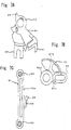
- 1 eine Vorderansicht, die einen Zustand darstellt, in welchem ein Türschloss gemäß einer Ausführungsform der Erfindung sich in einem entriegelten Zustand befindet;
- 2 eine Vorderansicht, die einen Zustand darstellt, in welchem das Türschloss gemäß der Ausführungsform der Erfindung sich in einem verriegelten Zustand befindet;
- 3A eine Schnittansicht, gesehen entlang einer Line A - A in 3B, und 3B eine Vorderansicht, die einen Verschlussmechanismus-Einrichtungsabschnitt eines ersten Gehäuseelements zeigt, dargestellt in 1;
- 4 einen Klinkenmechanismus des Türschlosses, wobei 4A eine Seitenansicht ist, die einen Zustand einer offenen Tür zeigt, und 4B eine Seitenansicht ist, die einen Zustand einer geschlossenen Tür zeigt;
- 5 eine Seitenansicht, die ein Verhältnis zwischen dem Klinkenmechanismus und einem Schließzylinder zeigt, dargestellt in den 4;
- 6 eine teilweise vergrößerte Vorderansicht eines Schlüsselbetätigungskraft-Übertragungsmechanismus, dargestellt in 1;
- 7A eine vergrößerte Vorderansicht einer Verschlussplatte, dargestellt in 1, 7B eine vergrößerte Vorderansicht eines Schlüssel-Zwischenhebels, dargestellt in 1, und 7C eine vergrößerte Vorderansicht eines Schlüssel-Verbindungsstücks, dargestellt in 1;
- 8 A eine Hinteransicht eines Schlüsselhebels, 8B eine Schnittansicht, gesehen entlang einer Linie B - B in 8A, und 8C eine teilweise vergrößerte Seitenansicht von einem Spitzen-Ende eines Rotationsstabes, dargestellt in 5;
- 9 eine Vorderansicht, die einen Zustand darstellt, in welchem ein Schaltbrett auf das erste Gehäuseelement gesetzt wurde, dargestellt in 1;
- 10 eine Vorderansicht, die einen Zustand darstellt, in welchem von dem entriegelten Zustand in 1 eine Verriegelungsoperation des Schließzylinders ausgeführt wird; und
- 11 eine Vorderansicht, die einen Zustand darstellt, in welchem von dem verriegelten Zustand eine Entriegelungsoperation des Schließzylinders ausgeführt wird, gezeigt in 2.
Show it: - 1 Fig. 3 is a front view showing a state in which a door lock according to an embodiment of the invention is in an unlocked state;
- 2 Fig. 13 is a front view showing a state in which the door lock according to the embodiment of the invention is in a locked state;
- 3A FIG. 13 is a sectional view seen along a line A - A in FIG 3B , and 3B FIG. 13 is a front view showing a lock mechanism installation portion of a first housing member shown in FIG 1 ;
- 4th a latch mechanism of the door lock, wherein 4A FIG. 13 is a side view showing a door open state, and FIG 4B Fig. 13 is a side view showing a state of a door closed;
- 5 FIG. 13 is a side view showing a relationship between the latch mechanism and a lock cylinder shown in FIG 4th ;
- 6th FIG. 13 is a partially enlarged front view of a key operation force transmission mechanism shown in FIG 1 ;
- 7A FIG. 8 is an enlarged front view of a closure plate shown in FIG 1 , 7B FIG. 8 is an enlarged front view of an intermediate key lever shown in FIG 1 , and 7C FIG. 3 is an enlarged front view of a key connector shown in FIG 1 ;
- 8 A a rear view of a key lever, 8B FIG. 11 is a sectional view seen along a line B - B in FIG 8A , and 8C FIG. 13 is a partially enlarged side view of a tip end of a rotary rod shown in FIG 5 ;
- 9 FIG. 13 is a front view showing a state in which a circuit board has been set on the first housing member shown in FIG 1 ;
- 10 FIG. 13 is a front view showing a state in which from the unlocked state in FIG 1 a locking operation of the key cylinder is performed; and
- 11 FIG. 13 is a front view showing a state in which an unlocking operation of the key cylinder is performed from the locked state shown in FIG 2 .
Ausführliche Beschreibung der bevorzugten AusführungsformenDetailed description of the preferred embodiments
Ausführungsformen der Erfindung werden beschrieben in Übereinstimmung mit den Figuren.Embodiments of the invention are described in accordance with the figures.
Die 1 und 2 stellen ein Türschloss gemäß einer Ausführungsform der Erfindung dar. Das Türschloss ist auf einer zu öffnenden und zu schließenden Tür eines Fahrzeugs montiert, um lösbar mit einem Schließbügel 1 (siehe 4 B), der auf einem Fahrzeugkörper eingerichtet ist, in Eingriff zu bringen zu sein. Das Türschloss ist mit einem Klinkenmechanismus ausgestattet, der mit dem Schließbügel 1 ineinander greift, und einem Verschlussmechanismus, der den Eingriffzustand des Schließbügels 1 durch den Klinkenmechanismus verriegelt und entriegelt.the 1 and 2 represent a door lock according to an embodiment of the invention. The door lock is mounted on an openable and closable door of a vehicle in order to be detachable with a striker 1 (please refer 4 B) configured to be engaged on a vehicle body. The door lock is equipped with a latch mechanism that works with the striker 1 meshes, and a locking mechanism that controls the engaged state of the striker 1 locked and unlocked by the latch mechanism.
Ein erstes Gehäuseelement 11 - in dem verschiedene Bauteile, die das Türschloss konfigurieren, eingerichtet sind - ist von oben gesehen in einer L-Form gebildet, wie in 3 A gezeigt, und schließt einen Einrichtungsabschnitt für einen Verschlussmechanismus 12 und einen Einrichtungsabschnitt für einen Klinkenmechanismus 13 ein. Wie in 3 B gezeigt, ist der Einrichtungsabschnitt für einen Verschlussmechanismus 12 ausgestattet mit Montageschaften 14a und 14b, welches Stützschafte sind für das drehbare Stützen eines Schließblechs 50 und eines inneren Hebels 40, welche im Folgenden beschrieben werden. Ein aufwärts gebogener, bogenförmiger Stützvorsprungsabschnitt 16 ist auf einer oberen Seite des Montageschafts 14a vorgesehen. Zwei Schlüssel-Verbindungsstück-Halterillen (Führungsrillen) 17 sind in einer vertikalen Richtung auf einer rechten Seite von und diagonal über dem Montageschaft 14a geformt. Die Schlüssel-Verbindungsstück-Halterillen 17 halten ein im Folgenden beschriebenes Schlüssel-Verbindungsstück 61. Auf einer rechten Seite von diesen Schlüssel-Verbindungsstück-Halterillen 17 ist eine Widerlagerwand 15a der Erfindung vorgesehen, in Richtung auf die näher liegende Seite in der Figur. Die Widerlagerwand 15a erstreckt sich in der vertikalen Richtung. Ein konkav geformter Positionierungsabschnitt (Positionierungsabschnitt) 15b, der in einer Richtung, entgegengesetzt zu den Schlüssel-Verbindungsstück-Halterillen 17 gebogen ist, ist an einem zentralen Abschnitt der Widerlagerwand 15a vorgesehen. Ein Schaftloch 18, in welchem ein im Folgenden beschriebener Knopfhebel 75 drehbar angeordnet ist, ist auf einer linken Seite des Montageschaftes 14b vorgesehen. Ein Einrichtungsabschnitt für einen Antriebsmotor 19 und ein Einrichtungsabschnitt für ein Nockenelement 20 sind auf einer linken Seite von und über dem Schaftloch 18 vorgesehen. Ein zweites Gehäuseelement 21, das auf dem Einrichtungsabschnitt für einen Verschlussmechanismus 12 des ersten Gehäuseelements 11 montiert ist, konfiguriert ein Gehäuse zusammen mit dem ersten Gehäuseelement 11.A first housing element 11 - in which various components that configure the door lock are set - is formed in an L-shape when viewed from above, as in FIG 3 A and includes an installation section for a locking mechanism 12th and a ratchet mechanism setup section 13th a. As in 3 B Shown is the installation section for a locking mechanism 12th equipped with mounting shafts 14a and 14b , which support shafts are for the rotatable support of a strike plate 50 and an inner lever 40 which are described below. An upwardly curved, arcuate support protrusion portion 16 is on an upper side of the mounting stem 14a intended. Two key connector retaining grooves (guide grooves) 17th are to the right of and diagonally across the mounting stem in a vertical direction 14a shaped. The key connector retaining grooves 17th hold a key connector described below 61 . On a right side of these key connector retaining grooves 17th is an abutment wall 15a of the invention provided in the direction of the closer side in the figure. The abutment wall 15a extends in the vertical direction. A concave-shaped positioning portion (positioning portion) 15b in a direction opposite to the key connector retaining grooves 17th is bent is at a central portion of the abutment wall 15a intended. A shaft hole 18th , in which a button lever described below 75 is rotatably arranged, is on a left side of the mounting shaft 14b intended. A device section for a drive motor 19th and a cam member arranging section 20th are to the left of and above the shaft hole 18th intended. A second housing element 21 that is on the locking mechanism setup section 12th of the first housing element 11 is mounted, configured a Housing together with the first housing element 11 .
Ein Unter-Gehäuse 24, montiert auf dem Einrichtungsmechanismus für einen Klinkenmechanismus 13 des ersten Gehäuseelements 11 bedeckt die Seite des Anschlagblocks 25 des Klinkenmechanismus, angeordnet auf dem Einrichtungsabschnitt für einen Klinkenmechanismus 13. Wie in den 4A und 4B gezeigt, ist der Anschlagblock 25 ausgestattet mit einem ausgesparten Einführabschnitt 26, um in Richtung auf den Einrichtungsabschnitt für einen Klinkenmechanismus 13 ausgespart zu sein. Der ausgesparte Einführabschnitt 26 ist ein Raum, durch den der Schließbügel 1 eingeführt ist. A sub-case 24 , mounted on the setting mechanism for a ratchet mechanism 13th of the first housing element 11 covers the side of the stop block 25th of the ratchet mechanism disposed on the ratchet mechanism installation section 13th . As in the 4A and 4B shown is the stop block 25th equipped with a recessed insertion section 26th to move toward the latch mechanism setup section 13th to be left out. The recessed lead-in section 26th is a space through which the striker 1 is introduced.
Eine Gabel 27, die den Klinkenmechanismus konfiguriert, ist drehbar auf einem Montageabschnitt 27a, über dem ausgesparten Einführabschnitt 26 montiert. Eine Kralle 28 ist auf einem Montageabschnitt 28a, unter dem ausgesparten Einführabschnitt 26 drehbar montiert. Ein Einführloch 31, durch welches ein Operations-Empfangsabschnitt 30 der Kralle 28 eingeführt wird, um in den Einrichtungsabschnitt für einen Klinkenmechanismus 13 hervorzustehen, ist auf einer linken Seite des Montageabschnitts 28 a gebildet.A fork 27 Configuring the ratchet mechanism is rotatable on a mounting portion 27a , above the recessed lead-in section 26th assembled. A claw 28 is on a mounting section 28a , under the recessed lead-in section 26th rotatably mounted. An insertion hole 31 through which an operation receiving section 30th the claw 28 is inserted into the fitting section for a ratchet mechanism 13th protruding is on a left side of the mounting section 28 a formed.
Die Gabel 27 des Klinkenmechanismus greift mit dem Schließbügel 1 lösbar ineinander. Die Kralle 28 greift mit der Gabel 27 ineinander, um einen Zustand beizubehalten, in welchem die Gabel 27 mit dem Schließbügel 1 ineinander greift. Bei dem Klinkenmechanismus drückt der Schließbügel 1 die Gabel 27 aufgrund einer Schließkraft der Tür, so dass die Gabel 27 sich in einer Richtung entgegen dem Uhrzeigersinn dreht, wie in 4A bis 4 B gezeigt. Ein Eingriffabschnitt 29 der Kralle 28 greift mit der Gabel 27 ineinander, und der Eingriffzustand des Schließbügels 1 durch die Gabel 27 wird beibehalten. In diesem Zustand, wenn der aufnehmende Betriebsabschnitt 30 der Kralle 28 aufwärts betätigt wird, wird die Kralle 28 in einer Richtung im Uhrzeigersinn gedreht und der Eingriffzustand zwischen der Gabel 27 und der Kralle 28 wird gelöst. Infolgedessen dreht sich die Gabel 27 in eine offene Position, dargestellt in 4A durch eine Vorspannkraft einer Feder (nicht gezeigt), und der Eingriffzustand des Schließbügels 1 wird gelöst.The fork 27 of the ratchet mechanism engages with the striker 1 detachable into each other. The claw 28 grabs with the fork 27 into each other to maintain a state in which the fork 27 with the striker 1 interlocks. In the case of the latch mechanism, the striker pushes 1 the fork 27 due to a closing force of the door so that the fork 27 rotates in a counterclockwise direction, as in 4A until 4 B shown. An engaging portion 29 the claw 28 grabs with the fork 27 into each other, and the state of engagement of the striker 1 through the fork 27 will be maintained. In this state, if the receiving operation section 30th the claw 28 is pressed upwards, the claw 28 rotated in a clockwise direction and the state of engagement between the fork 27 and the claw 28 will be solved. As a result, the fork rotates 27 to an open position, shown in 4A by a biasing force of a spring (not shown), and the engagement state of the striker 1 will be solved.
Wie in den 1 und 2 gezeigt, schließt der Verschlussmechanismus, der in dem ersten Gehäuseelement II eingebaut ist, ein Verbindungsstück 35 ein, das mit dem Operations-Empfangsabschnitt 35 der Kralle 28 ineinander greift, um die Kralle 28 in ihrer den Eingriff lösenden Richtung zu betätigen, sowie das Schließblech 50, das den Betrieb der Kralle 28 durch das Verbindungsstück 35 ermöglicht oder verhindert.As in the 1 and 2 As shown, the locking mechanism built into the first housing member II includes a connector 35 one that is associated with the operation receiving section 35 the claw 28 interlocks to the claw 28 to operate in their disengaging direction, as well as the strike plate 50 that is the operation of the claw 28 through the connector 35 enabled or prevented.
Ein Aufnahmeabschnitt 36 an dem unteren Ende des Verbindungsstücks 35 empfängt eine Betätigungskraft des inneren Hebels 40 oder eines äußeren Hebels 46, wobei dem Verbindungsstück 35 gestattet wird, sich aufwärts zu bewegen. In der entriegelten Position, die in 1 dargestellt ist, greift ein Betriebsabschnitt 37 in einem im Wesentlichen mittleren Abschnitt mit dem Operations-Empfangsabschnitt 30 der Kralle 28 ineinander, um zu verursachen, dass die Kralle 28 in einer den Eingriff lösenden Richtung operiert. Folglich kann der Eingriffzustand des Schließbügels 1 durch den Klinkenmechanismus gelöst werden. Ein Schließblech-Verbindungsabschnitt 38 an dem oberen Abschnitt des Verbindungsstücks 35 ist mit dem Schließblech 50 verbunden. Das Verbindungsstück 35 wird durch die drehende Bewegung des Schließblechs 50 in die entriegelte Position und die verriegelte Position bewegt. In der verriegelten Position, die in 2 gezeigt ist, ist der Betriebsabschnitt 37 abgetrennt in einer Position, in welcher der Betriebsabschnitt 37 nicht mit dem Öperations-Empfangsabschnitt 30 der Kralle 28 ineinander greifen kann. Folglich, selbst wenn das Verbindungsstück 35 durch den äußeren Hebel 46 oder den inneren Hebel 40 aufwärts bewegt wird, kann die Kralle 28 nicht in der den Eingriff lösenden Richtung betätigt werden. Folglich kann der Eingriffzustand des Schließbügels 1 durch den Klinkenmechanismus nicht gelöst werden.A receiving section 36 at the lower end of the connector 35 receives an operating force of the inner lever 40 or an external lever 46 , being the connector 35 is allowed to move upwards. In the unlocked position, which is in 1 is shown, an operating section engages 37 in a substantially middle section with the operation receiving section 30th the claw 28 into each other to cause that claw 28 operates in a disengaging direction. Consequently, the engaged state of the striker 1 can be released by the ratchet mechanism. A striking plate connecting section 38 on the upper portion of the connector 35 is with the strike plate 50 tied together. The connector 35 is made by the rotating movement of the strike plate 50 moved to the unlocked position and the locked position. In the locked position, which is in 2 is the operation section 37 separated in a position in which the operating section 37 not with the operation receiving section 30th the claw 28 can interlock. Hence, even if the connector 35 by the outer lever 46 or the inner lever 40 is moved upwards, the claw can 28 not operated in the disengaging direction. Consequently, the engaged state of the striker 1 cannot be released by the ratchet mechanism.
Der innere Hebel 40 ist mit einem inneren Türgriff (nicht gezeigt), der auf der inneren Seite der Tür vorgesehen ist, verbunden. Der innere Hebel 40 greift mit dem Eingriffabschnitt 36 des Verbindungsstücks 35 ineinander, um zu gestatten, dass das Verbindungsstück 35 in Richtung auf den Löseoperations-Empfangsabschnitt 30 der Kralle 28 arbeitet (gleitet). Der innere Hebel 40 umfasst einen Montageabschnitt 41, der drehbar auf dem Montageschaft 14 b des ersten Gehäuseelements 11 montiert ist. Der innere Hebel 40 ist mit einem Verbindungsabschnitt für den inneren Handgriff 42 ausgestattet, der sich erstreckt, um von einer Öffnung des zweiten Gehäuseelements 21, außerhalb des zweiten Gehäuseelements 21, hervorzustehen. Der Verbindungsabschnitt für den inneren Handgriff 42 ist mit dem inneren Türgriff verbunden. Der innere Hebel 40 ist mit einem im Wesentlichen J-förmigen Verbindungsstück-Operationsabschnitt 43 ausgestattet. Der Empfangsabschnitt 36 des Verbindungsstücks 35 ist in dem zusammengebauten Zustand auf einem Drehpunkt des Verbindungsstück-Operationsabschnitts 43 um den Montageabschnitt 41 angeordnet. Der innere Hebel 40 ist ferner mit einem Eingriffabschnitt 44 ausgestattet, der mit einem Eingriff-Aufnahmeabschnitt 79 des Knopf-Hebels 75 ineinander greift, um das Verbindungsstück 35 in die entriegelte Position zu bewegen, durch den Knopfhebel 75 und das Schließblech 50, in einem Zustand, in dem der Knopfhebel 75 in der verriegelten Position angeordnet ist.The inner lever 40 is connected to an inner door handle (not shown) provided on the inner side of the door. The inner lever 40 engages with the engaging portion 36 of the connector 35 into each other to allow the connector 35 toward the release operation receiving section 30th the claw 28 works (slides). The inner lever 40 includes a mounting section 41 that can be rotated on the mounting shaft 14th b of the first housing element 11 is mounted. The inner lever 40 is with a connecting section for the inner handle 42 equipped which extends to from an opening of the second housing member 21 , outside the second housing element 21 to stand out. The connecting section for the inner handle 42 is connected to the inner door handle. The inner lever 40 is with a substantially J-shaped connector operating section 43 fitted. The receiving section 36 of the connector 35 is in the assembled state on a fulcrum of the connector operating section 43 around the mounting section 41 arranged. The inner lever 40 is also with an engaging portion 44 equipped with an engagement receiving portion 79 the button lever 75 interlocks to form the connector 35 to move to the unlocked position by the button lever 75 and the strike plate 50 , in a state in which the button lever 75 is arranged in the locked position.
Wie in 5 gezeigt, tritt der äußere Hebel 46 durch das erste Gehäuseelement 11 und erstreckt sich nach innen und nach außen, und der äußere Hebel 46 ist drehbar montiert auf dem ersten Gehäuseelement 11. Der äußere Hebel 46 ist ausgestattet mit einem Verbindungsabschnitt für den äußeren Griff 48 an einem Abschnitt, der von dem ersten Gehäuseelement 11 nach außen hervorsteht. Der Verbindungsabschnitt für den äußeren Griff 48 ist mit einem äußeren Griff (nicht gezeigt) verbunden, der auf der Tür auf der äußeren Seite des Fahrzeugs vorgesehen ist. Wenn der äußere Griff betätigt wird, bewegt sich ein Verbindungsstück-Verbindungsabschnitt 47, der an einem Spitzen-Ende positioniert ist und mit einem Inneren des Aufnahmeabschnitts 36 verbunden ist, aufwärts, was verursacht, dass sich das Verbindungsstück 35 aufwärts bewegt.As in 5 shown, the outer lever occurs 46 through the first housing element 11 and extends inward and outward, and the outer lever 46 is rotatably mounted on the first housing element 11 . The outside lever 46 is equipped with a connecting section for the outer handle 48 at a portion of the first housing member 11 protrudes outwards. The connecting section for the outer handle 48 is connected to an outer handle (not shown) provided on the door on the outer side of the vehicle. When the outer handle is operated, a connector connecting portion moves 47 positioned at a tip end and having an interior of the receiving portion 36 connected upwards, which causes the connector to move 35 moved upwards.
Wie in 6 gezeigt, ist das Schließblech 50 drehbar befestigt auf dem Montageschaft 14 a des ersten Gehäuseelements 11. Wenn das Schließblech 50 durch einen im Folgenden beschriebenen Schlüssel-Zwischenhebel 55 oder den Knopf-Hebel 75 in der Richtung im Uhrzeigersinn gedreht wird, bewegt sich ein Verbindungsstück-Eingriffabschnitt 51 (siehe 7A), vorgesehen auf einem unteren Ende des Schließblechs 50, nach links, wobei sich auf diese Weise das Verbindungsstück 35 aus der entriegelten Position in die verriegelte Position bewegt. Wenn das Schließblech 50 in der Richtung entgegen dem. Uhrzeigersinn bewegt wird, bewegt sich der Verbindungsstück-Eingriffabschnitt 51 nach rechts, wobei auf diese Weise das Verbindungsstück 35 von der verriegelten Position in die entriegelte Position bewegt wird. Das Schließblech 50 ist ausgestattet mit einem Entriegelungsoperations-Empfangsabschnitt 52, der eine Entriegelungsoperation des Schlüssel-Zwischenhebels 55 empfängt, und einer rechten Kante 54, welche eine verriegelnde Operation des Schlüssel-Zwischenhebels 55 empfängt. Ein Knopfhebel-Eingriffabschnitt 53, der eine entriegelnde Operation und eine verriegelnde Operation des Knopf-Hebels 75 empfängt, ist auf der gegenüberliegenden Seite des Verbindungsstück-Eingriffabschnitts 51 vorgesehen.As in 6th shown is the strike plate 50 rotatably attached to the mounting shaft 14th a of the first housing element 11 . When the strike plate 50 by means of an intermediate key lever described below 55 or the button lever 75 is rotated in the clockwise direction, a link engaging portion moves 51 (please refer 7A) , provided on a lower end of the strike plate 50 , to the left, in this way the connector 35 moved from the unlocked position to the locked position. When the strike plate 50 in the direction opposite to that. Is moved clockwise, the link engaging portion moves 51 to the right, in this way the connector 35 is moved from the locked position to the unlocked position. The striking plate 50 is equipped with an unlock operation receiving section 52 showing an unlocking operation of the intermediate key lever 55 receives, and a right edge 54 showing a locking operation of the intermediate key lever 55 receives. A button lever engaging portion 53 having an unlocking operation and a locking operation of the button lever 75 receives is on the opposite side of the connector engaging portion 51 intended.
Ein zweiter bewegbarer Kontakt 95,welcher einen Verriegelungszustand-Erfassungsschalter konfiguriert, ist auf einer oberen Oberfläche des Schließbleches 50 angeordnet, auf der Seite des Knopfhebel-Eingriffabschnitts53. Der Verriegelungszustand-Erfassungsschalter erfasst den verriegelten Zustand oder den entriegelten Zustand der Tür, durch das Erfassen einer Bewegungsposition des Schließblechs 50.A second movable contact 95 configuring a lock state detection switch is on an upper surface of the strike plate 50 arranged on the button lever engaging portion 53 side. The locked state detection switch detects the locked state or the unlocked state of the door by detecting a moving position of the strike plate 50 .
Der Schlüssel-Zwischenhebel 55 ist drehbar auf dem Montageschaft 14a des ersten Gehäuseelements 11 zusammen mit dem Schließblech 50 montiert. Wie in 7B gezeigt, weist der Schlüssel-Zwischenhebel 55 im Wesentlichen eine Sektorform auf, welche einen ringförmigen Montageabschnitt 55a als einen höchsten Punkt aufweist. Der ringförmige Montageabschnitt 55a ist über dem Montageschaft 14a eingebaut. Der Schlüssel-Zwischenhebel 55 umfasst einen ersten Eingriffabschnitt 57a, der auf einer der Kanten des Schlüssel-Zwischenhebels 55 vorgesehen ist, einen zweiten Eingriffabschnitt 57 b, der auf der Seite der anderen Kante angeordnet ist und der von einer hinteren Oberfläche des Schlüssel-Zwischenhebels 55 in Richtung auf eine hintere Seite in der Figur hervorsteht, und einen Verbindungsabschnitt 56, der zwischen dem ersten Eingriffabschnitt 57 a und dem zweiten Eingriffabschnitt 57b vorgesehen ist und der ein elliptisches Einführloch aufweist. Durch das Drehen des Schlüssel-Zwischenhebels 55 in der Richtung des Uhrzeigersinns, stößt der erste Eingriffabschnitt 57a gegen die rechte Kante 54 des Schließblechs 50, um eine Verschlussoperation in Richtung auf das Schießblech 50 zu übertragen. Durch das Drehen des Schlüssel-Zwischenhebels 55 in der Richtung entgegen dem Uhrzeigersinn, stößt der zweite Eingriffabschnitt 57b gegen den Entriegelungsoperations-Empfangsabschnitt 52 des Schließblechs 50, um eine entriegelnde Operation auf das Schließblech 50 zu übertragen. Der Verbindungsabschnitt 56 ist über einem im Folgenden beschriebenen unteren kreisförmigen Vorsprung 62 des Schlüssel-Verbindungsstücks 61 eingebaut.The key intermediate lever 55 is rotatable on the mounting shaft 14a of the first housing element 11 together with the strike plate 50 assembled. As in 7B shown, the key intermediate lever 55 essentially a sector shape, which has an annular mounting portion 55a as having a highest point. The annular mounting section 55a is above the mounting shaft 14a built-in. The key intermediate lever 55 includes a first engagement portion 57a that is on one of the edges of the intermediate key lever 55 is provided, a second engagement portion 57 b, which is located on the side of the other edge and that from a rear surface of the key intermediate lever 55 protruding toward a rear side in the figure, and a connecting portion 56 that is between the first engagement portion 57 a and the second engagement portion 57b is provided and which has an elliptical insertion hole. By turning the key intermediate lever 55 in the clockwise direction, the first engaging portion abuts 57a against the right edge 54 of the strike plate 50 to perform a locking operation in the direction of the strike plate 50 transferred to. By turning the key intermediate lever 55 in the counterclockwise direction, the second engaging portion abuts 57b against the unlocking operation receiving section 52 of the strike plate 50 to do an unlocking operation on the strike plate 50 transferred to. The connecting section 56 is above a lower circular protrusion described below 62 of the key connector 61 built-in.
Der Schlüssel-Zwischenhebel 55 ist in Bezug auf das Schließblech 50 mit Spiel befestigt, so dass der Schlüssel-Zwischenhebel 55 nicht betätigt wird, selbst wenn sich das Schließblech 50 dreht. Genauer gesagt ist eine Distanz L1 vorgesehen als Spiel zwischen dem ersten Eingriffabschnitt 57a und der rechten Kante 54 des Schließblechs 50. Ferner ist ein Abstand L2 vorgesehen zwischen dem zweiten Eingriffabschnitt 57b und dem Entriegelungsoperations-Empfangsabschnitt 52 des Schließblechs 50.The key intermediate lever 55 is in relation to the strike plate 50 attached with play so that the key intermediate lever 55 is not operated, even if the strike plate is 50 turns. More precisely, it is a distance L1 provided as play between the first engagement portion 57a and the right edge 54 of the strike plate 50 . There is also a distance L2 provided between the second engagement portion 57b and the unlocking operation receiving section 52 of the strike plate 50 .
Ein erster bewegbarer Kontakt 91, welcher den Schlüsseloperations-Erfassungsschalter konfiguriert, ist auf dem Schlüssel-Zwischenhebel 55 angeordnet. Der Schlüsseloperations-Erfassungsschalter erfasst, dass die entriegelnde Operation oder die verriegelnde Operation des Schließzylinders 58 ausgeführt wird durch das Schlüssel-Verbindungsstück 61, den Schlüssel-Hebel 68 und einen Rotationsstab 71, durch das Erfassen einer sich bewegenden Position des Schlüssel-Zwischenhebels 55. Der Schlüsseloperations-Erfassungsschalter umfasst den ersten bewegbaren Kontakt 91 und einen feststehenden Kontakt 93 (siehe 9), eingerichtet auf einem im Folgenden beschriebenen Schaltbrett 101.A first movable contact 91 configuring the key operation detection switch is on the intermediate key lever 55 arranged. The key operation detection switch detects that the unlocking operation or the locking operation of the key cylinder 58 is carried out through the key connector 61 , the key lever 68 and a rotating rod 71 by detecting a moving position of the intermediate key lever 55 . The key operation detection switch includes the first movable contact 91 and a permanent contact 93 (please refer 9 ), set up on a switchboard described below 101 .
Wie in 7C gezeigt, umfasst das Schlüssel-Verbindungsstück 61 einen stabähnlichen Schlüssel-Verbindungsstückkörper 61a, der sich in der vertikalen Richtung erstreckt, einen oberen kreisförmigen Vorsprung 63, der auf einem oberen Ende des Schlüssel-Verbindungsstückkörpers 61a ausgebildet ist, und der in der vorwärts gerichteten Richtung und in der rückwärts gerichteten Richtung hervorsteht (auf der vorderen Seite und der hinteren Seite in dem Blatt der Figur), und der untere kreisförmig Vorsprung 62, der auf einem unteren Ende des Schlüssel-Verbindungsstückkörpers 61a vorgesehen ist und der in der vorwärts gerichteten Richtung und in der rückwärts gerichteten Richtung hervorsteht. Der obere kreisförmige Vorsprung 63 und der untere kreisförmige Vorsprung 62 werden durch die jeweiligen Schlüssel-Verbindungsstück-Halterillen 17 geführt, so dass das Schlüssel-Verbindungsstück 61 gehalten wird, um sich in der vertikalen Richtung in Bezug auf das erste Gehäuseelement 11 gerade hin und her zu bewegen. Der Schlüssel-Verbindungsstückkörper 61a der Erfindung ist integral mit einem Arm 65 vorgesehen, der von einer Seitenkante des Schlüssel-Verbindungsstückkörpers 61a hervorsteht und der sich parallel zu der Widerlagerwand 15a des ersten Gehäuseelements 11 entlang des Schlüssel-Verbindungsstückkörpers 61a erstreckt, und einem Eingriffabschnitt 66, der von einem Ende des Arms 65 in Richtung auf die Widerlagerwand 15a hervorsteht. Der Arm 65 setzt den Eingriffabschnitt 66 in Richtung auf die Widerlagerwand 15a federnd unter Vorspannung. Wenn der Eingriffabschnitt 66 und der konkav geformte Positionierungsabschnitt 15b miteinander eingepasst sind, wird das Schlüssel-Verbindungsstück 61 positioniert und der Schlüssel-Hebel 68 wird in seinem neutralen Zustand gehalten. Der Eingriffabschnitt 66 und der konkav geformte Positionierungsabschnitt 15b formen Positionierungsmittel.As in 7C shown includes the key connector 61 a rod-like key connector body 61a extending in the vertical direction has an upper one circular protrusion 63 resting on an upper end of the key connector body 61a and which protrudes in the forward direction and in the rearward direction (on the front side and the rear side in the sheet of the figure), and the lower circular protrusion 62 on a lower end of the key connector body 61a is provided and which protrudes in the forward direction and in the rearward direction. The top circular protrusion 63 and the lower circular protrusion 62 through the respective key connector retaining grooves 17th guided so that the key connector 61 is held to look in the vertical direction with respect to the first housing member 11 to move straight back and forth. The key connector body 61a of the invention is integral with an arm 65 provided by a side edge of the key connector body 61a protrudes and which is parallel to the abutment wall 15a of the first housing element 11 along the key connector body 61a extends, and an engaging portion 66 running from one end of the arm 65 towards the abutment wall 15a protrudes. The arm 65 sets the engaging portion 66 towards the abutment wall 15a resilient under pretension. When the engaging portion 66 and the concave-shaped positioning portion 15b are fitted with each other, becomes the key connector 61 positioned and the key lever 68 is kept in its neutral state. The engaging portion 66 and the concave-shaped positioning portion 15b form positioning means.
Der Schlüssel-Hebel 68 folgt dem Schließzylinder 58 (siehe 5), welcher so eingerichtet ist, um zur Außenseite der Tür freizuliegen, und dreht sich um einen Schaft 67 in der Richtung im Uhrzeigersinn oder in der Richtung entgegen dem Uhrzeigersinn. Der Schlüssel-Hebel 68 umfasst den Schaft 67, der auf einer Seite vorgesehen ist, ein länglich geformtes Einführloch 69, das auf der gegenüberliegenden Seite des Schaftes 67 vorgesehen ist, und einen konkav geformten Verbindungsabschnitt 72, der auf einer hinteren Seite des Schaftes 67 vorgesehen ist, wie in den 8A und 8B gezeigt. Der obere kreisförmige Vorsprung 63 des Schlüssel-Verbindungsstücks 61 ist in dem länglich geformten Einführloch 69 eingebaut. Der konkav geformte Verbindungsabschnitt 72 weist eine Querschnittsform auf, wie von der Vorderseite gesehen. Ein Verbindungs-Ende 73 (siehe 8C), welches einen Querschnitt aufweist, wie von der Vorderseite gesehen, ist auf einem Spitzen-Ende des Rotationsstabes 71 geformt. Das Verbindungs-Ende 73 ist in dem konkav geformten Verbindungsabschnitt 72 eingebaut. Der Rotationsstab 71 ist mit dem Schließzylinder 58 verbunden und diese rotieren integral zusammen mit einer Drehbewegung eines Schlüssels (nicht gezeigt), der in den Schließzylinder 58 eingeführt ist.The key lever 68 follows the lock cylinder 58 (please refer 5 ) which is arranged to expose to the outside of the door and rotates around a shaft 67 clockwise or counterclockwise direction. The key lever 68 includes the shaft 67 provided on one side has an elongated-shaped insertion hole 69 that is on the opposite side of the stem 67 is provided, and a concave-shaped connecting portion 72 that is on a rear side of the shaft 67 is provided as in the 8A and 8B shown. The top circular protrusion 63 of the key connector 61 is in the oblong shaped insertion hole 69 built-in. The concave-shaped connecting portion 72 has a cross-sectional shape as seen from the front. An end of the connection 73 (please refer 8C ), which has a cross section as viewed from the front, is on a tip end of the rotating rod 71 shaped. The end of the connection 73 is in the concave-shaped connecting portion 72 built-in. The rotating rod 71 is with the lock cylinder 58 connected and these rotate integrally together with a rotational movement of a key (not shown) inserted into the lock cylinder 58 is introduced.
Durch das Drehen des Schlüssels, der in den Schließzylinder 58 eingeführt ist, wird gemäß der vorstehend beschriebenen Konfiguration der Schlüssel-Hebel 68 zusammen mit dem Rotationsstab 71 gedreht. Das Schlüssel-Verbindungsstück 61 folgt dem Schlüssel-Hebel 68 und bewegt sich in der vertikalen Richtung, und der Schlüssel-Zwischenhebel 55 dreht sich aus seinem neutralen Zustand in der Richtung im Uhrzeigersinn oder in der Richtung entgegen dem Uhrzeigersinn. Der Schlüssel-Zwischenhebel 55, das Schlüssel-Verbindungsstück 61 und der Schlüsselhebel 68 formen einen Übertragungsmechanismus für die Schlüsseloperationskraft.By turning the key that is in the lock cylinder 58 is inserted, according to the configuration described above, the key lever 68 together with the rotation rod 71 turned. The key connector 61 follows the key lever 68 and moves in the vertical direction, and the key intermediate lever 55 rotates from its neutral state in the clockwise direction or in the counterclockwise direction. The key intermediate lever 55 , the key connector 61 and the key lever 68 form a transmission mechanism for the key operator.
Der Knopfhebel 75 wird drehbar in dem Schaftloch 18 des ersten Gehäuseelements 11 gehalten. Ein Knopfhebelseiten-Verbindungsabschnitt 76, der auf einem Ende des Knopfhebels 75 gebildet ist, ist mit einem Verschlussknopf (nicht gezeigt), der auf der inneren Seite der Tür vorgesehen ist, durch eine Öffnung des zweiten Gehäuseelements 21 verbunden. Ein Schließblech-Eingriffabschnitt 77 ist auf dem anderen Ende des Knopfhebels 75 vorgesehen. Der Schließblech-Eingriffabschnitt 77 greift mit dem Knopfhebel-Eingriffabschnitt 53 des Schließblechs 50 ineinander. Wenn der Knopfhebel 75 in Verbindung mit einer Operation des Verschluss-Knopfes gedreht wird, wird das Schließblech 50 betätigt, um das Verbindungsstück 35 in die verriegelnde Position oder die entriegelnde Position zu bewegen. Genauer gesagt, wenn der Knopfhebel 75 durch den Verschluss-Knopf in die Richtung entgegen dem Uhrzeigersinn gedreht wird, dreht der Schließblech-Eingriffabschnitt 77 das. Schließblech 50 in die verriegelte Position. Wenn der Knopfhebel 75 durch den Verschluss-Knopf in die Richtung im Uhrzeigersinn gedreht wird, dreht der Schließblech-Eingriffabschnitt 77 das Schließblech 50 in die entriegelte Position. Ein Nocken-Aufnahmeabschnitt 78, der mit einer Nockenrille 85 eines Nockenelements 84, angeordnet auf einem hinteren Abschnitt, ineinander greift, ist über dem Schaftloch 18 vorgesehen. Der Knopfhebel 75 ist mit dem Eingriff-Aufnahmeabschnitt 79 ausgebildet, der eine Drehbewegung des inneren Hebels 40 empfängt, nur in einem Zustand, in dem der Knopfhebel 75 sich in die verriegelte Position bewegt.The button lever 75 becomes rotatable in the shaft hole 18th of the first housing element 11 held. A button lever side connecting portion 76 that is on one end of the button lever 75 is formed is with a lock button (not shown), which is provided on the inner side of the door, through an opening of the second housing member 21 tied together. A striker engaging portion 77 is on the other end of the button lever 75 intended. The strike plate engaging portion 77 engages with the button lever engaging portion 53 of the strike plate 50 into each other. When the button lever 75 In conjunction with an operation, the lock button is turned, the strike plate becomes 50 operated to the connector 35 to move to the locking position or the unlocking position. More precisely when the button lever 75 is rotated in the counterclockwise direction by the lock knob, the striker engaging portion rotates 77 the. striking plate 50 to the locked position. When the button lever 75 is rotated in the clockwise direction by the lock knob, the striker engaging portion rotates 77 the strike plate 50 to the unlocked position. A cam receiving section 78 , the one with a cam groove 85 of a cam element 84 , interlocked on a rear portion, is above the shaft hole 18th intended. The button lever 75 is with the engagement receiving portion 79 formed, the rotational movement of the inner lever 40 receives, only in a state in which the button lever 75 moves to the locked position.
Ein Antriebsmotor 81, der neben dem Nockenelement 84 eingerichtet ist, wird von einem im Folgenden beschriebenen Anschussstück 104 (siehe 9) durch einen Motor-Terminal 87 angetrieben. Der Motor-Terminal 87 ist direkt verbunden mit einem Inneren des Anschlussstücks 104. Der Antriebsmotor 81 rotiert das Nockenelement 84 durch eine Abtriebswelle 82 vor und zurück. Das Nockenelement 84 ist rotierbar eingerichtet, so dass es gegenüber liegend des Nocken-Empfangsabschnitts 78 von dem Knopfhebel 75 angeordnet ist. Eine Nockenrille 85 weist einen in einer oberen Oberfläche des Nockenelements 84 ausgesparten Zustand auf, welche gegenüberliegend des Knopfhebels 75eingerichtet ist, so dass sich ein Abstand zwischen einem Mittelpunkt und einem äußeren Umfang der Nockenrille 85 graduell vergrößert. Wenn das Nockenelement 84 rotiert wird, so dass sich der Nocken-Empfangsabschnitt 78 in Richtung auf den Mittelpunkt bewegt, wird das Verbindungsstück 35 betätigt, um sich durch den Knopfhebel 75 und das Schließblech 50 in die verriegelte Position zu bewegen. Wenn das Nockenelement 84 andererseits so rotiert wird, dass sich der Nocken-Empfangsabschnitt 78 in Richtung auf den äußeren Umfang bewegt, wird das Verbindungsstück 35 betätigt, um sich durch den Knopfhebel 75 und das Schließblech 50 in die entriegelte Position zu bewegen.A drive motor 81 that is next to the cam element 84 is set up, is from a connecting piece described below 104 (please refer 9 ) through a motor terminal 87 driven. The motor terminal 87 is directly connected to an interior of the connector 104 . The drive motor 81 the cam element rotates 84 by an output shaft 82 back and forth. The cam element 84 is arranged to be rotatable so that it is opposite to the cam receiving section 78 of the Button lever 75 is arranged. A cam groove 85 has one in an upper surface of the cam member 84 recessed state, which is set opposite the button lever 75 so that a distance between a center and an outer periphery of the cam groove 85 gradually enlarged. When the cam element 84 is rotated so that the cam receiving section 78 moved towards the center point, the connector becomes 35 operated to yourself by the button lever 75 and the strike plate 50 to move to the locked position. When the cam element 84 on the other hand, it is rotated so that the cam receiving section 78 moved towards the outer periphery, the connector 35 operated to yourself by the button lever 75 and the strike plate 50 to move to the unlocked position.
Wie in 9 gezeigt, ist das Schaltbrett 101 durch ein Gewinde an dem ersten Gehäuseelement 11 gesichert, so dass das Schaltbrett 101 das Schließblech 50 und den Schlüssel-Zwischenhebel 55 bedeckt und gegenüber dem ersten bewegbaren Kontakt 91 und dem zweiten bewegbaren Kontakt 95 angeordnet ist. Der feststehende Kontakt 93 ist auf einer Oberfläche des Schaltbretts 101 angebracht, welche gegenüberliegend der bewegbaren Kontakte 91 und 95 angeordnet ist. Der feststehende Kontakt 93 umfasst ein Strukturstück, mit dem die bewegbaren Kontakte 91 und 95 in einen Zustand eines Kurzschlusses gleiten.As in 9 shown is the switchboard 101 by a thread on the first housing element 11 secured so that the switchboard 101 the strike plate 50 and the key intermediate lever 55 covered and opposite the first movable contact 91 and the second movable contact 95 is arranged. The fixed contact 93 is on a surface of the control panel 101 attached, which opposite the movable contacts 91 and 95 is arranged. The fixed contact 93 includes a structural piece with which the movable contacts 91 and 95 slide into a state of short circuit.
Eine externe ECU (nicht gezeigt) ist durch das Anschlussstück 104 mit dem feststehenden Kontakt 93 verbunden. Die externe ECU kann die Operation des Schließzylinders 58 sowie den verriegelten Zustand und den entriegelten Zustand des Türschlosses erfassen, durch das Erfassen, dass ein leitender Zustand des feststehenden Kontaktes 93 durch Bewegungen der bewegbaren Kontakte 91 und 95 umgeschaltet ist.An external ECU (not shown) is through the connector 104 with the fixed contact 93 tied together. The external ECU can control the operation of the lock cylinder 58 and detect the locked state and the unlocked state of the door lock by detecting that the fixed contact is in a conductive state 93 by movements of the movable contacts 91 and 95 is switched.
Als nächstes wird das Einsetzen des Schlüssel-Zylinders 58 in den Schlüssel-Hebel 66 beschrieben, der auf dem ersten Gehäuseelement 11 montiert ist.Next is the insertion of the key cylinder 58 in the key lever 66 described on the first housing element 11 is mounted.
Um den Schlüssel-Zylinder 58 in den Schlüssel-Hebel 68 einzusetzen, wird das Verbindungs-Ende 73 des Rotationsstabes 71, verbunden mit dem Schlüsselzylinder 58, in den konkav geformten Verbindungsabschnitt 72 des Schlüssel-Hebels 68 eingesetzt. Zu diesem Zeitpunkt, da das Verbindungs-Ende 73 des konkav geformten Verbindungsabschnitts 72 die Querschnittsformen aufweist, ist es notwendig, den Schlüssel-Hebel 68 in seinem neutralen Zustand zu halten, entsprechend der neutralen Position des Schlüssel-Zylinders 58. Jedoch ist der Schlüssel-Zwischenhebel 55 in Bezug auf das Schließblech 50 mit Spiel eingerichtet, wie vorstehend beschrieben. Folglich war es schwierig, in dem neutralen Zustand den Schlüssel-Hebel 68 zu halten, der durch das Schlüssel-Verbindungsstück 61 mit dem Schlüssel-Zwischenhebel 55 verbunden ist.To the key cylinder 58 in the key lever 68 will be the end of the connection 73 of the rotation bar 71 connected to the key cylinder 58 , into the concave-shaped connecting portion 72 the key lever 68 used. At this point, since the connection end 73 of the concave-shaped connecting portion 72 which has cross-sectional shapes, it is necessary to use the key lever 68 in its neutral state, corresponding to the neutral position of the key cylinder 58 . However, this is the key intermediate lever 55 in relation to the strike plate 50 set up with game as described above. Consequently, it was difficult to keep the key lever in the neutral state 68 to keep that through the key connector 61 with the key intermediate lever 55 connected is.
In dieser Ausführungsform jedoch ist es möglich, das Schlüssel-Verbindungsstück 61 zu positionieren und den Schlüssel-Hebel 58 in dem neutralen Zustand zu halten, durch den gegenseitigen Eingriff des konkav geformten Positionierungsabschnitts 15 b und des Eingriffabschnitts 66. Folglich ist es möglich, die Einbauoperation zwischen dem konkav geformten Verbindungsabschnitt 72 und dem Verbindungs-Ende 73 zu vereinfachen, und ohne weiteres den Schlüssel-Zylinder 58 in den Schlüssel-Hebel 68 einzusetzen, wodurch die Operation des Zusammenbauens vereinfacht wird.In this embodiment, however, it is possible to use the key connector 61 to position and the key lever 58 in the neutral state by the mutual engagement of the concave-shaped positioning portion 15th b and the engaging portion 66 . As a result, it is possible to perform the installation operation between the concave-shaped connecting portion 72 and the connection end 73 to simplify, and readily the key cylinder 58 in the key lever 68 to be used, thereby simplifying the assembling operation.
Da der Eingriffabschnitt 66 des Schlüssel-Verbindungsstücks 61 lösbar und federnd mit dem konkav geformten Positionierungsabschnitt 15b ineinander greift, kann das Schlüssel-Verbindungsstück 61 betätigt werden in einem Zustand, in dem der Eingriffabschnitt 66 vorgesehen verbleibt. Folglich ist es nicht nötig, den Arm 65 und den Eingriffabschnitt 66 zu lösen, nachdem das Schlüssel-Verbindungsstück 61 zusammengebaut ist, wodurch die Operation des Zusammenbauens weiter vereinfacht wird.Since the engaging portion 66 of the key connector 61 releasable and resilient with the concave shaped positioning portion 15b interlocks, the key connector can 61 are operated in a state in which the engaging portion 66 remains provided. Consequently, there is no need to arm 65 and the engaging portion 66 to loosen after the key connector 61 is assembled, thereby further simplifying the assembling operation.
Das Schlüssel-Verbindungsstück 61, welches sich in einem Zustand hin und her bewegt, in dem ein Ende des Schlüssel-Verbindungsstücks 61 mit dem Schlüssel-Hebel 68 verbunden ist und das andere Ende des Schlüssel-Verbindungsstücks 61 mit dem Schlüssel-Zwischenhebel 55 verbunden ist, neigt dazu - aufgrund von Aussparungen für das Bewegen verschiedener Verbindungsabschnitte - zu klappern. Durch das Ausstatten des Schlüssel-Verbindungsstücks 61 mit dem Arm 65 und dem Eingriffabschnitt 66 greifen der Eingriffabschnitt 66 und der konkav geformte Positionierungsabschnitt 15b ineinander, und das Schlüssel-Verbindungsstück 61 wird durch eine federnde Kraft des Arms 65 unter Vorspannung gesetzt. Folglich ist es möglich, das Klappern des Schlüssel-Verbindungsstücks 61 zu unterdrücken, wodurch ungewöhnliche Geräusche, erzeugt durch das Klappern, verhindert werden.The key connector 61 which reciprocates in a state in which one end of the key connector 61 with the key lever 68 and the other end of the key connector 61 with the key intermediate lever 55 tends to rattle - due to recesses for moving different connecting sections. By equipping the key connector 61 with the arm 65 and the engaging portion 66 grip the engaging portion 66 and the concave-shaped positioning portion 15b into each other, and the key connector 61 is made by a resilient force of the arm 65 placed under tension. As a result, it is possible for the key connector to rattle 61 suppress, thereby preventing unusual noises generated by the rattling.
Die Positionierungsmittel umfassen den konkav geformten Positionierungsabschnitt 15b, der in der Widerlagerwand 15a des ersten Gehäuseelements 11 gebildet ist, und den Eingriffabschnitt 66, der integral auf dem Schlüssel-Verbindungsstück 61 gebildet ist. Folglich ist es möglich, durch die einfache Konfiguration die Positionierungsmittel bereitzustellen.The positioning means include the concave-shaped positioning portion 15b , the one in the abutment wall 15a of the first housing element 11 is formed, and the engaging portion 66 that is integral to the key connector 61 is formed. As a result, it is possible to provide the positioning means with the simple configuration.
Da der Arm 65 und der Eingriffabschnitt 66 integral auf dem Schlüssel-Verbindungsstück 61 gebildet sind, sind keine individuellen oder separaten Spezialteile nötig, und die Produktionskosten können reduziert werden.Because the arm 65 and the engaging portion 66 integral on the key connector 61 are formed, no individual or separate special parts are required, and the production cost can be reduced.
Da der Schlüssel-Zwischenhebel 55, welcher durch das Schlüssel-Verbindungsstück 61 in seinem neutralen Zustand positioniert ist, mit dem Schlüsseloperations-Erfassungsschalter ausgestattet ist, ist es möglich, den Schlüssel-Zwischenhebel 55 zuverlässig in der neutralen Position zu halten, wobei ermöglicht wird, einen Leitungstest des Schlüssel-Operationskraft-Erfassungsschalters zum Zeitpunkt der Herstellung auszuführen.Because the key intermediate lever 55 which through the key connector 61 is positioned in its neutral state, equipped with the key operation detection switch, it is possible to use the key intermediate lever 55 reliably maintained in the neutral position, thereby making it possible to conduct a conduction test of the key operating force detecting switch at the time of manufacture.
Die verriegelnde Operation und die entriegelnde Operation des Türschlosses, die durch den Schließzylinder 58 ausgeführt werden, werden im Folgenden beschrieben.The locking operation and the unlocking operation of the door lock performed by the lock cylinder 58 are described below.
In einem entriegelten Zustand, wie in 1 gezeigt, wenn der Schließzylinder 58, der außerhalb des Fahrzeugs angeordnet ist, in einer Verriegelungsrichtung betätigt wird, wie in 10 gezeigt, dreht sich in 10 der Schlüsselhebel 68 des Verschlussmechanismus von dem neutralen Zustand in der Richtung entgegen dem Uhrzeigersinn um den Schaft 67. Dann wird der Eingriff zwischen dem Eingriffabschnitt 66 des Schlüssel-Verbindungsstücks 61 und des konkav geformten Abschnitts 15b gelöst und das Schlüssel-Verbindungsstück 61 bewegt sich abwärts, wenn der Eingriffabschnitt 66 mit der Widerlagerwand 15a gleitet. Gemäß dieser Bewegung dreht sich der Schlüssel-Zwischenhebel 55 in der Richtung im Uhrzeigersinn und das Schließblech 50 dreht sich auch in der Richtung im Uhrzeigersinn, wobei auf diese Weise das Verbindungsstück 85 in die verriegelte Position bewegt wird. Wenn der Schießzylinder 58 in die neutrale Position zurückbewegt wird und der Schlüssel aus dem Schließzylinder 58herausgezogen wird, dreht sich danach der Schlüssel-Hebel 68 in der Richtung im Uhrzeigersinn, das Schlüssel-Verbindungsstück 61 bewegt sich aufwärts und der Schlüssel-Zwischenhebel 55 dreht sich in der Richtung entgegen dem Uhrzeigersinn. Gemäß dieser Operation kehren der Schlüssel-Hebel 68, das Schlüssel-Verbindungsstück 61 und der Schlüssel-Zwischenhebel 55 in ihre neutralen Positionen zurück, und der Eingriffabschnitt 66 des Schlüssel-Verbindungsstücks 61 und der konkav geformte Abschnitt 15b werden erneut in den Eingriffzustand versetzt (wie in 2 gezeigt).In an unlocked state, as in 1 shown when the lock cylinder 58 located outside the vehicle is operated in a locking direction, as in FIG 10 shown turns in 10 the key lever 68 of the locking mechanism from the neutral state in the counterclockwise direction around the shaft 67 . Then the engagement between the engagement portion 66 of the key connector 61 and the concave-shaped portion 15b loosened and the key connector 61 moves downward when the engaging portion 66 with the abutment wall 15a slides. The key intermediate lever rotates in accordance with this movement 55 in the clockwise direction and the strike plate 50 also rotates in the clockwise direction, in this way the connector 85 is moved to the locked position. When the shooting barrel 58 is returned to the neutral position and the key is withdrawn from the lock cylinder 58, the key lever then rotates 68 in the clockwise direction, the key connector 61 moves upwards and the key intermediate lever 55 rotates in the counterclockwise direction. According to this operation, return the key lever 68 , the key connector 61 and the key intermediate lever 55 return to their neutral positions, and the engaging portion 66 of the key connector 61 and the concave shaped portion 15b are put into the engaged state again (as in 2 shown).
Wenn in dem verriegelten Zustand, der in 2 gezeigt ist, der Schließzylinder 58, der außerhalb des Fahrzeugs angeordnet ist, in der Entriegelungsrichtung betätigt wird, wie in 11 gezeigt, dreht sich der Schlüssel-Hebel 68 des Verschlussmechanismus von dem neutralen Zustand in der Richtung im Uhrzeigersinn in 11 um den Schaft 67. Gemäß dieser Bewegung wird der Eingriff zwischen dem Eingriffabschnitt 66 des Schlüssel-Verbindungsstücks 61 und dem konkav geformten Abschnitt 15b gelöst, und das Schlüssel-Verbindungsstück 61 bewegt sich aufwärts, wenn der Eingriffabschnitt 66 mit der Widerlagerwand 15a gleitet. Gemäß dieser Bewegung dreht sich der Schlüssel-Zwischenhebel 55 in der Richtung entgegen dem Uhrzeigersinn, das Schließblech 50 dreht sich auch in der Richtung entgegen dem Uhrzeigersinn, wobei auf diese Weise das Verbindungsstück 35 in die entriegelnde Position bewegt wird. Danach, wenn der Schließzylinder 58 in die neutrale Position zurück bewegt wird und der Schlüssel aus dem Schließzylinder 58 gezogen wird, dreht sich der Schließzylinder 68 in der Richtung entgegen dem Uhrzeigersinn, das Schlüssel-Verbindungsstück 61 bewegt sich abwärts und der Schlüssel-Zwischenhebel 55 dreht in die Richtung im Uhrzeigersinn. Gemäß dieser Operation kehren der Schlüssel-Hebel 68, das Schlüssel-Verbindungsstück 61 und der Schlüssel-Zwischenhebel 55 in ihre neutralen Positionen zurück, und der Eingriffabschnitt 66 des Schlüssel-Verbindungsstücks 61 und der konkav geformte Abschnitt 15b werden erneut in den Eingriffzustand versetzt (Zustand von 1).When in the locked state shown in 2 shown is the lock cylinder 58 located outside the vehicle is operated in the unlocking direction, as in FIG 11 shown, the key lever turns 68 of the locking mechanism from the neutral state in the clockwise direction in 11 around the shaft 67 . According to this movement, the engagement between the engaging portion becomes 66 of the key connector 61 and the concave shaped portion 15b loosened, and the key connector 61 moves up when the engaging portion 66 with the abutment wall 15a slides. The key intermediate lever rotates in accordance with this movement 55 in the counterclockwise direction, the strike plate 50 also rotates in the counterclockwise direction, in this way the connector 35 is moved to the unlocking position. After that when the lock cylinder 58 is moved back to the neutral position and the key is removed from the lock cylinder 58 is pulled, the lock cylinder rotates 68 in the counterclockwise direction, the key connector 61 moves downwards and the key intermediate lever 55 rotates in the clockwise direction. According to this operation, return the key lever 68 , the key connector 61 and the key intermediate lever 55 return to their neutral positions, and the engaging portion 66 of the key connector 61 and the concave shaped portion 15b are put into the engagement state again (state of 1 ).
Das Türschloss der Erfindung ist nicht auf die Ausführungsform beschränkt und kann verschiedenartig modifiziert werden.The door lock of the invention is not limited to the embodiment and can be variously modified.
Formen und Größen des Arms 65 und des Eingriffabschnitts 66 sind nicht begrenzt, solange der Eingriffabschnitt 66 mit dem konkav geformten Positionierungsabschnitt 15b ineinandergreifen, um das Schlüssel-Verbindungsstück 61 zu positionieren, und der Eingriffabschnitt 66 mit der Widerlagerwand 15a gleitet.Shapes and sizes of the arm 65 and the engaging portion 66 are not limited as long as the engaging portion 66 with the concave-shaped positioning portion 15b interlock to form the key connector 61 to position, and the engaging portion 66 with the abutment wall 15a slides.
Formen und Größen der Widerlagerwand 15a und des konkav geformten Positionierungsabschnitts 15b sind nicht begrenzt, solange das Schlüssel-Verbindungsstück 61 durch den Eingriffabschnitt 66 positioniert wird.Shapes and sizes of the abutment wall 15a and the concave-shaped positioning portion 15b are not limited as long as the key connector 61 through the engaging portion 66 is positioned.