DE102012110132A1 - Sparkline representations of process control system alarms - Google Patents
Sparkline representations of process control system alarms Download PDFInfo
- Publication number
- DE102012110132A1 DE102012110132A1 DE102012110132A DE102012110132A DE102012110132A1 DE 102012110132 A1 DE102012110132 A1 DE 102012110132A1 DE 102012110132 A DE102012110132 A DE 102012110132A DE 102012110132 A DE102012110132 A DE 102012110132A DE 102012110132 A1 DE102012110132 A1 DE 102012110132A1
- Authority
- DE
- Germany
- Prior art keywords
- alarm
- sparkline
- process variable
- operator
- trend
- Prior art date
- Legal status (The legal status is an assumption and is not a legal conclusion. Google has not performed a legal analysis and makes no representation as to the accuracy of the status listed.)
- Pending
Links
Images

Classifications
-
- G—PHYSICS
- G05—CONTROLLING; REGULATING
- G05B—CONTROL OR REGULATING SYSTEMS IN GENERAL; FUNCTIONAL ELEMENTS OF SUCH SYSTEMS; MONITORING OR TESTING ARRANGEMENTS FOR SUCH SYSTEMS OR ELEMENTS
- G05B23/00—Testing or monitoring of control systems or parts thereof
- G05B23/02—Electric testing or monitoring
- G05B23/0205—Electric testing or monitoring by means of a monitoring system capable of detecting and responding to faults
- G05B23/0259—Electric testing or monitoring by means of a monitoring system capable of detecting and responding to faults characterized by the response to fault detection
- G05B23/0267—Fault communication, e.g. human machine interface [HMI]
-
- G—PHYSICS
- G01—MEASURING; TESTING
- G01R—MEASURING ELECTRIC VARIABLES; MEASURING MAGNETIC VARIABLES
- G01R13/00—Arrangements for displaying electric variables or waveforms
- G01R13/02—Arrangements for displaying electric variables or waveforms for displaying measured electric variables in digital form
-
- G—PHYSICS
- G05—CONTROLLING; REGULATING
- G05B—CONTROL OR REGULATING SYSTEMS IN GENERAL; FUNCTIONAL ELEMENTS OF SUCH SYSTEMS; MONITORING OR TESTING ARRANGEMENTS FOR SUCH SYSTEMS OR ELEMENTS
- G05B23/00—Testing or monitoring of control systems or parts thereof
- G05B23/02—Electric testing or monitoring
- G05B23/0205—Electric testing or monitoring by means of a monitoring system capable of detecting and responding to faults
- G05B23/0259—Electric testing or monitoring by means of a monitoring system capable of detecting and responding to faults characterized by the response to fault detection
- G05B23/0267—Fault communication, e.g. human machine interface [HMI]
- G05B23/027—Alarm generation, e.g. communication protocol; Forms of alarm
-
- G—PHYSICS
- G06—COMPUTING; CALCULATING OR COUNTING
- G06F—ELECTRIC DIGITAL DATA PROCESSING
- G06F11/00—Error detection; Error correction; Monitoring
- G06F11/30—Monitoring
-
- G—PHYSICS
- G09—EDUCATION; CRYPTOGRAPHY; DISPLAY; ADVERTISING; SEALS
- G09G—ARRANGEMENTS OR CIRCUITS FOR CONTROL OF INDICATING DEVICES USING STATIC MEANS TO PRESENT VARIABLE INFORMATION
- G09G5/00—Control arrangements or circuits for visual indicators common to cathode-ray tube indicators and other visual indicators
- G09G5/003—Details of a display terminal, the details relating to the control arrangement of the display terminal and to the interfaces thereto
-
- G—PHYSICS
- G05—CONTROLLING; REGULATING
- G05B—CONTROL OR REGULATING SYSTEMS IN GENERAL; FUNCTIONAL ELEMENTS OF SUCH SYSTEMS; MONITORING OR TESTING ARRANGEMENTS FOR SUCH SYSTEMS OR ELEMENTS
- G05B15/00—Systems controlled by a computer
- G05B15/02—Systems controlled by a computer electric
-
- G—PHYSICS
- G05—CONTROLLING; REGULATING
- G05B—CONTROL OR REGULATING SYSTEMS IN GENERAL; FUNCTIONAL ELEMENTS OF SUCH SYSTEMS; MONITORING OR TESTING ARRANGEMENTS FOR SUCH SYSTEMS OR ELEMENTS
- G05B19/00—Programme-control systems
- G05B19/02—Programme-control systems electric
-
- G—PHYSICS
- G05—CONTROLLING; REGULATING
- G05B—CONTROL OR REGULATING SYSTEMS IN GENERAL; FUNCTIONAL ELEMENTS OF SUCH SYSTEMS; MONITORING OR TESTING ARRANGEMENTS FOR SUCH SYSTEMS OR ELEMENTS
- G05B21/00—Systems involving sampling of the variable controlled
- G05B21/02—Systems involving sampling of the variable controlled electric
-
- G—PHYSICS
- G06—COMPUTING; CALCULATING OR COUNTING
- G06F—ELECTRIC DIGITAL DATA PROCESSING
- G06F11/00—Error detection; Error correction; Monitoring
- G06F11/07—Responding to the occurrence of a fault, e.g. fault tolerance
-
- G—PHYSICS
- G06—COMPUTING; CALCULATING OR COUNTING
- G06F—ELECTRIC DIGITAL DATA PROCESSING
- G06F15/00—Digital computers in general; Data processing equipment in general
- G06F15/02—Digital computers in general; Data processing equipment in general manually operated with input through keyboard and computation using a built-in program, e.g. pocket calculators
-
- G—PHYSICS
- G06—COMPUTING; CALCULATING OR COUNTING
- G06F—ELECTRIC DIGITAL DATA PROCESSING
- G06F3/00—Input arrangements for transferring data to be processed into a form capable of being handled by the computer; Output arrangements for transferring data from processing unit to output unit, e.g. interface arrangements
- G06F3/01—Input arrangements or combined input and output arrangements for interaction between user and computer
-
- G—PHYSICS
- G09—EDUCATION; CRYPTOGRAPHY; DISPLAY; ADVERTISING; SEALS
- G09G—ARRANGEMENTS OR CIRCUITS FOR CONTROL OF INDICATING DEVICES USING STATIC MEANS TO PRESENT VARIABLE INFORMATION
- G09G2340/00—Aspects of display data processing
- G09G2340/14—Solving problems related to the presentation of information to be displayed
-
- G—PHYSICS
- G09—EDUCATION; CRYPTOGRAPHY; DISPLAY; ADVERTISING; SEALS
- G09G—ARRANGEMENTS OR CIRCUITS FOR CONTROL OF INDICATING DEVICES USING STATIC MEANS TO PRESENT VARIABLE INFORMATION
- G09G5/00—Control arrangements or circuits for visual indicators common to cathode-ray tube indicators and other visual indicators
Landscapes
- Engineering & Computer Science (AREA)
- Physics & Mathematics (AREA)
- General Physics & Mathematics (AREA)
- Human Computer Interaction (AREA)
- Automation & Control Theory (AREA)
- Theoretical Computer Science (AREA)
- Quality & Reliability (AREA)
- General Engineering & Computer Science (AREA)
- Computer Hardware Design (AREA)
- Testing And Monitoring For Control Systems (AREA)
- User Interface Of Digital Computer (AREA)
Abstract
Sparkline-Darstellungen von Prozessleitsystem-Alarmen werden beschrieben. Ein Benutzerschnittstellen-Apparat für ein Prozessleistsystem, einschließlich einem Operatordisplay-Modul, um eine Operator-Anwendung auf einem Display darzustellen. Die Benutzeroberfläche beinhaltet auch eine Alarmschnittstelle, die durch die Operator-Anwendung auf dem Display dargestellt wird. Die Alarmschnittstelle beinhaltet eine mit einem Alarm verbundene Sparkline, um den Trend einer Prozessvariable im Verhältnis zum Alarmgrenzwert eines damit verbunden Alarms grafisch darzustellen.Sparkline representations of process control system alarms are described. A user interface apparatus for a process control system, including an operator display module to display an operator application on a display. The user interface also includes an alarm interface, which is displayed by the operator application on the display. The alarm interface includes a sparkline connected to an alarm to graph the trend of a process variable relative to the alarm limit of an associated alarm.
Description
GEGENSTAND DER OFFENLEGUNGSUBJECT OF DISCLOSURE
Diese Offenlegung bezieht sich allgemein auf Prozessleitsysteme und insbesondere auf Sparkline-Darstellungen von Prozessleitsystem-Alarmen.This disclosure relates generally to process control systems, and more particularly to sparkline representations of process control system alarms.
HINTERGRUNDBACKGROUND
Prozessleitsysteme, wie jene, die bei der Erdölverarbeitung, bei chemischen oder anderen Arbeitsvorgängen verwendet werden, enthalten normalerweise eine oder mehrere Prozesssteuerungen, die mit einem oder mehreren Feldgeräten kommunikativ via analoge, digitale oder kombinierte analog/digitale Busse gekoppelt sind. Feldgeräte, die zum Beispiel Ventile, Ventilstellungsregler, Schalter und Transmitter sein können (z. B. Temperatur-, Druck- und Durchflusssensoren), leisten eine Prozessleitsystemfunktion innerhalb des Arbeitsvorganges, wie etwa das Öffnen oder Schließen von Ventilen und das Messen von Prozessparametern. Die Prozesssteuerungen empfangen Signale, die Aufschluss über Prozessmessungen von Feldgeräten geben, und verarbeiten dann diese Informationen, um Kontrollsignale zu erzeugen und Steuerprogramme in Kraft zu setzen, andere Prozesssteuerungsentscheidungen zu treffen und Prozessleitsystem-Alarme auszulösen. Häufig können Prozessleitinformationen für langfristiges Historisieren für nachträgliche Analysen und/oder Ausbildung aufgezeichnet werden.Process control systems, such as those used in petroleum processing, chemical or other operations, typically include one or more process controllers communicatively coupled to one or more field devices via analog, digital, or combined analog / digital buses. Field devices, which may be, for example, valves, valve positioners, switches, and transmitters (eg, temperature, pressure, and flow sensors), perform a process control system function within the operation, such as opening or closing valves, and measuring process parameters. The process controllers receive signals that provide information about process measurements from field devices and then process that information to generate control signals and enforce control programs, make other process control decisions, and trigger process control system alarms. Often, process history information for long-term historization can be recorded for subsequent analysis and / or training.
Informationen von den Feldgeräten und/oder der Steuerung werden normalerweise durch Datenautobahnen oder Kommunikationsnetzwerke an ein oder mehrere Hardwareeinheiten bereitgestellt, solche wie Bedienerworkstations, Personal Computer, Daten-Historians, Berichtsgeneratoren, zentralisierte Datenbanken usw. Solche Geräte befinden sich normalerweise in Kontrollzentren und/oder an anderen Standorten, die von der rauen Produktionsumgebung entfernt liegen. Diese Hardwareeinheiten betreiben z. B. Anwendungen, die es dem Operator ermöglichen, eine Vielfalt von Funktionen bezüglich des Arbeitsvorgangs des Prozessleitsystems auszuüben, wie etwa den gegenwärtig erzielten Fortschritt zu sehen, einen Betriebszustand zu ändern, Einstellungen eines Steuerprogramms zu ändern, die Tätigkeit der Prozesssteuerung und/oder der Feldgeräte zu modifizieren, Alarme zu sehen, die von Feldgeräten und/oder Prozesssteuerungen erzeugt wurden, den Arbeitsvorgang des Prozesses zu simulieren, zwecks Personalausbildung und/oder den Arbeitsvorgang zu evaluieren.Information from the field devices and / or the controller is normally provided by data highways or communication networks to one or more hardware units, such as operator workstations, personal computers, data historians, report generators, centralized databases, etc. Such devices are typically located in control centers and / or on other locations that are remote from the harsh production environment. These hardware units operate z. B. Applications that allow the operator to perform a variety of functions related to the operation of the process control system, such as to see the progress currently made to change an operating state, change settings of a control program, the activity of the process control and / or field devices to modify, to see alarms generated by field devices and / or process controls, to simulate the operation of the process, to evaluate personnel training and / or the operation.
Diese Hardwareeinheiten beinhalten normalerweise eine oder mehrere Benutzeroberflächen, um sachdienliche Informationen bezüglich des/der Betriebszustands (-zustände) des Leitsystems und/oder anderen Geräten innerhalb des Leitsystems zu zeigen. Displaybeispiele nehmen die Form von Alarmdisplays an, die Alarme empfangen oder zeigen, die von Steuerungen oder Geräten innerhalb des Prozessleitsystems erzeugt wurden, Steuerungsdisplays, die auf den Betriebszustand oder Zustände der Steuerung oder Steuerungen eines anderen Gerätes oder anderen Geräten innerhalb des Prozessleitsystems deuten usw.These hardware units typically include one or more user interfaces to present pertinent information regarding the operating state (s) of the control system and / or other devices within the control system. Display examples take the form of alarm displays that receive or display alarms generated by controllers or devices within the process control system, control displays that indicate the operating state or states of the controller or controllers of another device or devices within the process control system, and so on.
In einem Prozessleitsystem ist es üblich, dass Tausende von Alarmen im Prozessleitsystem definiert werden, um dem Operator mögliche Probleme im Prozessleitsystem zu melden. Alarme sind definiert, zum Beispiel, um Leute und/oder Personal zu schützen, um Umweltvorfälle zu vermeiden, und/oder während der Herstellung Produktqualität sicherzustellen. Normalerweise wird jeder Alarm durch eine oder mehrere Einstellungen definiert (z. B. Alarmgrenzwert), die definieren, wann ein Problem entstanden ist oder unmittelbar bevorsteht, und/oder um den Alarm auszulösen und eine Priorität (z. B. kritisch oder Warnhinweis) festzulegen, um die Wichtigkeit des Alarms, im Verhältnis zu anderen Alarmen, zu definieren.In a process control system, it is common for thousands of alarms to be defined in the process control system to notify the operator of potential problems in the process control system. Alarms are defined, for example, to protect people and / or personnel, to prevent environmental incidents, and / or to ensure product quality during manufacturing. Normally, each alarm is defined by one or more settings (eg alarm limit) that define when a problem has arisen or is imminent, and / or to trigger the alarm and set a priority (eg, critical or warning) to define the importance of the alarm, in relation to other alarms.
Normalerweise werden Alarme dem Operator oder Operatoren in der Form einer Liste oder Tabelle präsentiert (z. B. dargestellt). In solch einem Format wird jeder Alarm als eine einzelne Linie in der Liste präsentiert mit spezifischen Daten, die den Operator über den Zustand des Leitsystems informieren. Daten in einer bereitgestellten Alarmliste können, zum Beispiel, eine Beschreibung des Alarms und die Uhrzeit, wann er ausgelöst wurde, mit einschließen.Normally, alarms are presented to the operator or operators in the form of a list or table (eg, shown). In such a format, each alarm is presented as a single line in the list with specific data informing the operator of the state of the control system. Data in a provided alarm list may include, for example, a description of the alarm and the time when it was triggered.
Sie kann auch die Alarmquelle, die Wichtigkeit oder Priorität des Alarms, der Zustand des Alarms (z. B. bestätigt oder nicht, aktiv oder nicht), die Art der Prozessvariable, die den Alarm ausgelöst hat, den Wert der Prozessvariable usw. mit einschließen. Sowie Informationen von den Prozesssteuerungen und/oder Feldgeräten erhalten werden, kann die Alarmliste in Echtzeit aktualisiert werden, um den Operatoren Zugriff auf alle gegenwärtigen Informationen bezüglich aller aktiven Alarme zu ermöglichen.It may also include the alarm source, the importance or priority of the alarm, the state of the alarm (eg, confirmed or not, active or not), the type of process variable that triggered the alarm, the value of the process variable, and so on , As information is received from the process controllers and / or field devices, the alarm list can be updated in real time to allow the operators access to all current information regarding all active alarms.
ZUSAMMENFASSUNGSUMMARY
Methoden und Apparat eine Sparkline-Darstellung eines Prozessleitsystem-Alarms zu zeigen, werden offenbart. In einem Beispiel beinhaltet ein Benutzeroberflächenapparat für ein Prozessleitsystem ein Operatordisplay-Modul, um eine Operator-Anwendung auf dem Display zu zeigen. Die Benutzeroberfläche beinhaltet auch eine Alarmschnittstelle, die durch die Operator-Anwendung auf dem Display dargestellt wird. Die Alarmschnittstelle beinhaltet eine mit einem Alarm verbundene Sparkline, um den Trend einer Prozessvariable im Verhältnis zum Alarmgrenzwert eines damit verbunden Alarms, grafisch darzustellen.Methods and apparatus to show a sparkline representation of a process control system alarm are disclosed. In one example, a user interface apparatus for a process control system includes an operator display module to display an operator application on the display. The user interface also includes an alarm interface, which is displayed by the operator application on the display. The alarm interface includes a sparkline connected to an alarm to monitor the trend of a process variable in relation to Alarm limit of an associated alarm to graph.
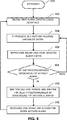
In einem anderen Beispiel beinhaltet eine Methode das Erhalten von Prozessvariable-Daten von einer Prozesssteuerung, die mit einer Prozessvariablen verbunden ist; das Erhalten von Alarmdaten von einem Alarm, der mit der Prozessvariable verbunden ist; das Erzeugen einer Sparkline auf der Basis der Prozessvariable-Daten und den Alarmdaten, um einen Trend von der Prozessvariable im Verhältnis zum Alarmgrenzwert des Alarms grafisch darzustellen; und das Aufzeigen der Sparkline mittels einer Benutzeroberfläche.In another example, one method involves obtaining process variable data from a process controller connected to a process variable; receiving alarm data from an alarm associated with the process variable; generating a sparkline based on the process variable data and the alarm data to graphically represent a trend of the process variable relative to the alarm limit of the alarm; and showing the Sparkline via a user interface.
KURZBESCHREIBUNG DER ZEICHNUNGENBRIEF DESCRIPTION OF THE DRAWINGS
AUSFÜHRLICHE BESCHREIBUNGDETAILED DESCRIPTION
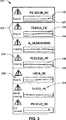
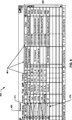
Alarmdisplays sind ein primäres Hilfsmittel, durch das Prozessleitsystem-Operatoren sich über mögliche Probleme in einem Prozessleitsystem bewusst bleiben. Eine typische Alarmschnittstelle beinhaltet eine Tabelle aller aktiven Alarme. Die Informationen, die von einer Alarmschnittstelle für jeden aktiven Alarm gezeigt werden, können die Zeit der Alarmaktivierung, die Art des Alarms (z. B. hoch, niedrig usw.), die Schwellwerteinstellung (z. B. 400 gall.) oder den Alarmgrenzwert und die Prozessvariablen (z. B. 408 gall.) mit einschließen.Alarm displays are a primary tool by which process control system operators remain aware of potential problems in a process control system. A typical alarm interface includes a table of all active alarms. The information displayed by an alarm interface for each active alarm may include the time of alarm activation, the type of alarm (eg, high, low, etc.), the threshold setting (eg, 400 gallons), or the alarm threshold and include process variables (eg, 408 gallons).
Außerdem werden Alarmdisplays normalerweise in Echtzeit aktualisiert, um dem Operator die aktuellsten Informationen vom Zustand des Prozessleitsystems zu vermitteln. Auch wenn Operatoren die aktuellsten Daten bezüglich eines Prozessleitsystems haben, ist die Änderung von Prozessvariablen, die mit dem aktiven Alarm verbunden sind, seitdem die dazugehörigenIn addition, alarm displays are normally updated in real time to provide the operator with the most up-to-date information about the state of the process control system. Even though operators have the most up-to-date data regarding a process control system, the change of process variables associated with the active alarm has since been the associated one
Alarme aktiviert wurden, (d. h. die laufenden Trends und/oder Verhalten der Prozessvariablen) für Analysen nicht immer frei zugänglich. Ohne diese Information können Operatoren die Bedeutung und/oder den Sinn des Alarms falsch interpretieren, was eine ineffektive Korrekturmaßnahme zur Folge haben kann. Operatoren können sich z. B. an gewisse aus Erfahrung häufig vorkommende Alarme gewöhnen. Aufgrund von bisherigen Erfahrungen können Operatoren falsche Annahmen über die eigentlichen Ursachen (d. h. der ursprüngliche Umstand und/oder Zustand des Prozessleitsystems, das den Alarm verursachte) machen, denn obwohl die gleichen häufig vorkommenden Alarme ausgelöst wurden, die Prozessdynamik anders ist. Ein Operator kann sich z. B. an eine Prozessvariable gewöhnt haben, die normalerweise einen Zustand vom langsamen Zurückgehen auf Normal hat (d. h. Kein-Alarm), aufgrund normaler Pozessdynamik und/oder weil der Alarm mit zu viel Hysterese und/oder Ausschaltverzögerung nicht richtig konfiguriert ist. Dadurch kann der Operator solch einen Alarm für eine beträchtliche Zeit ignorieren, wenn schnelle Aktion eigentlich nötig wäre, weil der tatsächliche Zustand des Prozessleitsystems anders ist als der Operator annimmt. Mit anderen Worten können sich Operatoren daran gewöhnen auf einen oder mehrere Alarme auf eine gewisse Weise zu reagieren, die in der Vergangenheit effektiv war, (z. B. eine Zeit lang zu warten, bevor reagiert wird). Wenn jedoch der wirkliche Zustand des Prozessleitsystems anders als angenommen ist, aber trotzdem die gleichen Alarme signalisiert werden, kann es sein, dass Operatoren die Unterschiede im Prozessleitsystem nicht erkennen können, und können daher auf gewöhnliche Art und Weise mit geringer oder gar keiner Auswirkung reagieren. Genauso wie das falsche Einschätzen der laufenden Trends von Prozessvariablen, die mit speziellen Alarmen verbunden sind, nachdem diese Alarme aktiv wurden, zu inkorrekten Schlussfolgerungen über den Zustand des Prozessleitsystems und/oder die eigentliche Ursache führen kann, kann ein inkorrektes Verstehen des Verhaltens von Prozessvariablen, die zum Auslösen entsprechender Alarme führten, auch zu falscher Festlegung eigentlicher Ursachen und/oder ineffektiver Operatorreaktion führen.Alarms are activated (ie the current trends and / or behavior of process variables) are not always freely accessible for analysis. Without this information, operators may misinterpret the meaning and / or meaning of the alarm, which may result in an ineffective corrective action. Operators can z. B. get used to certain frequent alarms from experience. Based on past experience, operators can make false assumptions about the root cause (ie, the original circumstance and / or state of the process control system that caused the alarm), because although the same common alarms were triggered, the process dynamics are different. An operator can z. For example, have become accustomed to a process variable that normally has a state of slowing back to normal (i.e., no alarm) due to normal process dynamics and / or because the alarm is not properly configured with too much hysteresis and / or off delay. This allows the operator to ignore such an alarm for a considerable amount of time if fast action is actually needed because the actual state of the process control system is different than the operator assumes. In other words, operators may become accustomed to responding to one or more alerts in a manner that has been effective in the past (eg, waiting a while before responding). However, if the actual state of the process control system is different, but the same alarms are still signaled, operators may not be able to see the differences in the process control system, and may therefore respond in the usual way with little or no effect. Just as misjudging the current trends of process variables associated with specific alarms after these alarms become active can lead to incorrect conclusions about the state of the process control system and / or the root cause, incorrect understanding of the behavior of process variables, which led to the triggering of corresponding alarms, also lead to incorrect determination of actual causes and / or ineffective operator reaction.
Demzufolge beinhalten die hier beschriebenen Beispiele eine Trendliniengrafik (hierin als Sparkline bezeichnet), die verwendet werden kann, um eine optische Darstellung des Verhaltens einer Prozessvariablen zu zeigen, jenes Verhaltens, das zum Auslösen des Alarms führt, sowohl als auch jenes, das nach dem Auslösen des Alarms erfolgt. Die gezeigten Sparklines können eine festgesetzte Höhe und Breite haben und müssen keine Bezeichnungen und Skalen beinhalten, müssen aber die sich verändernde Beziehung einer Prozessvariablen zu einem entsprechenden Alarmgrenzwert während der jüngsten Zeitspanne zeigen. Die Sparklines ermöglichen den Operatoren die Alarmschnittstelle abzufragen, anstatt relevante Informationen zu lesen, um das Verhalten und/oder den Zustand einer Prozessvariablen in Bezug auf den Alarmgrenzwert zu verstehen. Zusätzlich sind Operatoren mit Hilfe von Sparklines in der Lage festzustellen, ob der sich entwickelnde Zustand einer Prozessvariablen, die mit aktiven Alarmen verbunden ist, einem akzeptablen Zustand mit normalem Verhalten entspricht, oder eine außergewöhnliche Abweichung des normalen Verhaltens ist und somit besondere Aufmerksamkeit erfordert. Weil das laufende Verhalten einer Prozessvariablen dargestellt wird, können Operatoren außerdem auch erkennen, ob ihre Maßnahmen die möglichen Probleme zu korrigieren funktionieren, oder ob sie weitere und/oder andere Maßnahmen ergreifen sollten.Accordingly, the examples described herein include a trend line graph (referred to herein as a sparkline) that may be used to provide an optical representation of the behavior of a person Show process variables, those behaviors that trigger the alarm, as well as those that occur after the alarm is triggered. The sparklines shown may have a fixed height and width, and need not include labels and scales, but must show the changing relationship of a process variable to a corresponding alarm limit during the most recent period of time. The sparklines allow operators to interrogate the alarm interface rather than reading relevant information to understand the behavior and / or state of a process variable relative to the alarm limit. In addition, with the help of sparklines, operators are able to determine whether the evolving state of a process variable associated with active alarms conforms to an acceptable state of normal behavior, or is an abnormal deviation of normal behavior and thus requires special attention. In addition, because the current behavior of a process variable is presented, operators can also see if their actions work to correct the potential problems, or whether they should take further and / or other action.
Die beispielsweise Operatorstation
Die beispielsweise Operation-Station
Die beispielsweise Operatorstation
Das beispielsweise LAN
Die beispielsweise Steuerung
Zusätzlich zu den beispielsweise intelligenten Feldgeräten
Die beispielsweise Steuerung
Während
Um dem Operator eine Interaktion mit dem beispielsweisen Prozessor
Das beispielsweise Betriebssystem
Um Prozessleitsystem Operatordisplays und/oder -Anwendungen zu zeigen, beinhaltet die Operatorstation
Während eine Beispielmethode der Installation einer Operatorstation
Der derzeitige Zustand der Prozessvariable entspricht der Sparkline
Wie in
Anderenfalls können einige oder alle beispielsweisen Verfahren von
Das Verfahren von
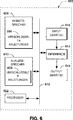
Die Prozessorplattform
Der Prozessor
Die Prozessorplattform
Obwohl bestimmte Methoden, Apparate und Herstellerartikel hier beschrieben wurden, ist die Reichweite dieses Patentes nicht darauf beschränkt. Solche Beispiele sind als nicht einschränkende, veranschaulichende Beispiele gemeint. Im Gegenteil, dieses Patent umfasst alle Methoden, Apparate und Herstellungsartikel, die einigermaßen in den Rahmen der angehängten Ansprüche fallen, entweder wörtlich oder nach der Äquivalenzlehre.Although certain methods, apparatus and manufacturer's articles have been described herein, the scope of this patent is not limited thereto. Such examples are meant to be non-limiting, illustrative examples. On the contrary, this patent includes all methods, apparatuses and articles of manufacture which fall reasonably within the scope of the appended claims, either literally or according to the doctrine of equivalency.
Claims (24)
Applications Claiming Priority (2)
| Application Number | Priority Date | Filing Date | Title |
|---|---|---|---|
| US13/279,589 | 2011-10-24 | ||
| US13/279,589 US20130100136A1 (en) | 2011-10-24 | 2011-10-24 | Sparkline presentations of process control system alarms |
Publications (1)
| Publication Number | Publication Date |
|---|---|
| DE102012110132A1 true DE102012110132A1 (en) | 2013-04-25 |
Family
ID=47359348
Family Applications (1)
| Application Number | Title | Priority Date | Filing Date |
|---|---|---|---|
| DE102012110132A Pending DE102012110132A1 (en) | 2011-10-24 | 2012-10-24 | Sparkline representations of process control system alarms |
Country Status (5)
| Country | Link |
|---|---|
| US (1) | US20130100136A1 (en) |
| JP (5) | JP6522871B2 (en) |
| CN (1) | CN103064359B (en) |
| DE (1) | DE102012110132A1 (en) |
| GB (1) | GB2496280B (en) |
Cited By (1)
| Publication number | Priority date | Publication date | Assignee | Title |
|---|---|---|---|---|
| EP3796119A1 (en) * | 2019-09-23 | 2021-03-24 | Siemens Aktiengesellschaft | Extended trend display of process data and secondary alarms |
Families Citing this family (14)
| Publication number | Priority date | Publication date | Assignee | Title |
|---|---|---|---|---|
| US20130100136A1 (en) * | 2011-10-24 | 2013-04-25 | Kim Ordean Van Camp | Sparkline presentations of process control system alarms |
| US10803636B2 (en) | 2013-03-15 | 2020-10-13 | Fisher-Rosemount Systems, Inc. | Graphical process variable trend monitoring, predictive analytics and fault detection in a process control system |
| US10013149B2 (en) | 2013-03-15 | 2018-07-03 | Fisher-Rosemount Systems, Inc. | Graphical process variable trend monitoring for a process control system |
| US9983575B2 (en) | 2013-04-09 | 2018-05-29 | Fisher-Rosemount Systems, Inc. | Systems and methods to graphically display process control system information |
| US10514668B2 (en) | 2013-03-15 | 2019-12-24 | Fisher-Rosemount Systems, Inc. | Graphical process variable trend monitoring in a process control system using a navigation pane |
| US10180681B2 (en) | 2013-03-15 | 2019-01-15 | Fisher-Rosemount Systems, Inc. | Graphical process variable trend monitoring with zoom features for use in a process control system |
| DE102014007383A1 (en) * | 2014-05-20 | 2015-11-26 | Abb Technology Ag | Device for managing and configuring field devices of an automation system |
| US9921569B2 (en) * | 2015-03-06 | 2018-03-20 | Yokogawa Electric Corporation | Field device commissioning system and method |
| US10044577B2 (en) * | 2015-11-04 | 2018-08-07 | International Business Machines Corporation | Visualization of cyclical patterns in metric data |
| US10657776B2 (en) | 2016-10-24 | 2020-05-19 | Fisher-Rosemount Systems, Inc. | Alarm handling and viewing support in a process plant |
| WO2020064712A1 (en) * | 2018-09-28 | 2020-04-02 | Siemens Aktiengesellschaft | Method for improving the prioritization of messages, software component, operating and observation system, and automation system |
| EP3913445A1 (en) * | 2020-05-20 | 2021-11-24 | Siemens Aktiengesellschaft | Alarm-related representation of trend curve diagrams in the context of the control and observation of a technical installation |
| EP4030252B1 (en) * | 2021-01-18 | 2023-05-10 | Siemens Aktiengesellschaft | Load management in the display of an alarm message display |
| EP4099114B1 (en) * | 2021-05-31 | 2023-07-19 | Siemens Aktiengesellschaft | Method for detecting a restricted operation and observation of a technical installation, operating and monitoring system and process control system |
Family Cites Families (31)
| Publication number | Priority date | Publication date | Assignee | Title |
|---|---|---|---|---|
| JPS61217897A (en) * | 1985-03-22 | 1986-09-27 | 三菱電機株式会社 | Process monitor |
| JPH031297A (en) * | 1989-05-30 | 1991-01-07 | Toshiba Corp | Alarm monitor |
| US6285966B1 (en) * | 1998-06-25 | 2001-09-04 | Fisher Controls International, Inc. | Function block apparatus for viewing data in a process control system |
| JP2000020124A (en) * | 1998-07-07 | 2000-01-21 | Mitsubishi Electric Corp | Plant monitor and control system |
| US6774786B1 (en) * | 2000-11-07 | 2004-08-10 | Fisher-Rosemount Systems, Inc. | Integrated alarm display in a process control network |
| US6577323B1 (en) * | 1999-07-01 | 2003-06-10 | Honeywell Inc. | Multivariable process trend display and methods regarding same |
| JP2001042931A (en) * | 1999-07-29 | 2001-02-16 | Mitsubishi Heavy Ind Ltd | Time-series data processor |
| JP4056032B2 (en) * | 1999-10-27 | 2008-03-05 | 株式会社東芝 | Plant equipment management device |
| US6965806B2 (en) * | 2001-03-01 | 2005-11-15 | Fisher-Rosemount Systems Inc. | Automatic work order/parts order generation and tracking |
| JP2005531826A (en) * | 2002-03-01 | 2005-10-20 | フィッシャー−ローズマウント システムズ, インコーポレイテッド | How to generate integrated warnings in process plants |
| JP2003337621A (en) * | 2002-05-22 | 2003-11-28 | Yamatake Corp | Process-monitoring device, process monitoring program, and recording medium recorded with process monitoring program |
| JP2004199258A (en) | 2002-12-17 | 2004-07-15 | Toshiba Corp | Process monitoring device |
| US7515977B2 (en) * | 2004-03-30 | 2009-04-07 | Fisher-Rosemount Systems, Inc. | Integrated configuration system for use in a process plant |
| JP2007536634A (en) * | 2004-05-04 | 2007-12-13 | フィッシャー−ローズマウント・システムズ・インコーポレーテッド | Service-oriented architecture for process control systems |
| US8032621B1 (en) * | 2006-01-03 | 2011-10-04 | Emc Corporation | Methods and apparatus providing root cause analysis on alerts |
| US20070157105A1 (en) * | 2006-01-04 | 2007-07-05 | Stephen Owens | Network user database for a sidebar |
| US8014880B2 (en) * | 2006-09-29 | 2011-09-06 | Fisher-Rosemount Systems, Inc. | On-line multivariate analysis in a distributed process control system |
| WO2008042758A2 (en) * | 2006-09-29 | 2008-04-10 | Fisher-Rosemount Systems, Inc. | Multivariate monitoring and diagnostics of process variable data |
| US8108790B2 (en) * | 2007-03-26 | 2012-01-31 | Honeywell International Inc. | Apparatus and method for visualization of control techniques in a process control system |
| BRPI0815489A2 (en) * | 2007-08-14 | 2017-03-21 | Shell Int Research | near real-time systems for continuous on-line monitoring of operating states in an industrial production facility and continuous on-line monitoring of a continuously operating industrial production facility and prediction of impending process abnormalities, and method for near real-time monitoring of the operation of a continuous or batch industrial production facility |
| US8191005B2 (en) * | 2007-09-27 | 2012-05-29 | Rockwell Automation Technologies, Inc. | Dynamically generating visualizations in industrial automation environment as a function of context and state information |
| US8436871B2 (en) * | 2008-04-18 | 2013-05-07 | General Electric Company | Space efficent sortable table |
| US10289671B2 (en) * | 2008-05-07 | 2019-05-14 | Microsoft Technology Licensing, Llc | Graphically displaying selected data sources within a grid |
| US8571696B2 (en) * | 2009-06-10 | 2013-10-29 | Fisher-Rosemount Systems, Inc. | Methods and apparatus to predict process quality in a process control system |
| US9323234B2 (en) * | 2009-06-10 | 2016-04-26 | Fisher-Rosemount Systems, Inc. | Predicted fault analysis |
| US9164501B2 (en) * | 2009-10-05 | 2015-10-20 | Fisher-Rosemount Systems, Inc. | Methods and apparatus to manage data uploading in a process control environment |
| US9285799B2 (en) * | 2009-11-23 | 2016-03-15 | Fisher-Rosemount Systems, Inc. | Methods and apparatus to dynamically display data associated with a process control system |
| US9557735B2 (en) * | 2009-12-10 | 2017-01-31 | Fisher-Rosemount Systems, Inc. | Methods and apparatus to manage process control status rollups |
| US20110239109A1 (en) * | 2010-03-24 | 2011-09-29 | Mark Nixon | Methods and apparatus to display process data |
| US8717374B2 (en) * | 2010-09-13 | 2014-05-06 | Fisher-Rosemount Systems, Inc. | Methods and apparatus to display process control information |
| US20130100136A1 (en) * | 2011-10-24 | 2013-04-25 | Kim Ordean Van Camp | Sparkline presentations of process control system alarms |
-
2011
- 2011-10-24 US US13/279,589 patent/US20130100136A1/en not_active Abandoned
-
2012
- 2012-10-23 GB GB1219048.4A patent/GB2496280B/en active Active
- 2012-10-24 JP JP2012234306A patent/JP6522871B2/en active Active
- 2012-10-24 DE DE102012110132A patent/DE102012110132A1/en active Pending
- 2012-10-24 CN CN201210422993.2A patent/CN103064359B/en active Active
-
2017
- 2017-10-12 JP JP2017198171A patent/JP6751381B2/en active Active
-
2019
- 2019-08-02 JP JP2019142795A patent/JP7468970B2/en active Active
-
2022
- 2022-08-23 JP JP2022132381A patent/JP2022172193A/en active Pending
-
2023
- 2023-07-31 JP JP2023124452A patent/JP2023153916A/en active Pending
Cited By (3)
| Publication number | Priority date | Publication date | Assignee | Title |
|---|---|---|---|---|
| EP3796119A1 (en) * | 2019-09-23 | 2021-03-24 | Siemens Aktiengesellschaft | Extended trend display of process data and secondary alarms |
| WO2021058344A1 (en) * | 2019-09-23 | 2021-04-01 | Siemens Aktiengesellschaft | Extended trend indicator for process data and secondary alarms |
| US11892831B2 (en) | 2019-09-23 | 2024-02-06 | Siemens Aktiengesellschaft | Extended trend indicator for process data and secondary alarms |
Also Published As
| Publication number | Publication date |
|---|---|
| JP6522871B2 (en) | 2019-05-29 |
| JP2022172193A (en) | 2022-11-15 |
| JP7468970B2 (en) | 2024-04-16 |
| JP2013093029A (en) | 2013-05-16 |
| CN103064359B (en) | 2018-01-05 |
| GB201219048D0 (en) | 2012-12-05 |
| CN103064359A (en) | 2013-04-24 |
| JP2019207728A (en) | 2019-12-05 |
| GB2496280A (en) | 2013-05-08 |
| JP6751381B2 (en) | 2020-09-02 |
| GB2496280B (en) | 2019-05-08 |
| US20130100136A1 (en) | 2013-04-25 |
| JP2023153916A (en) | 2023-10-18 |
| JP2018049631A (en) | 2018-03-29 |
Similar Documents
| Publication | Publication Date | Title |
|---|---|---|
| DE102012110132A1 (en) | Sparkline representations of process control system alarms | |
| DE102012110129A1 (en) | TIMELINE PRESENTATIONS OF PROCESS CONTROL SYSTEM ALARMS | |
| DE10217107B4 (en) | Advanced device alarms in a process control system | |
| DE102008019053B4 (en) | Method for operating a plant of process automation technology | |
| DE102014103185A1 (en) | Background survey of diagnostic data from metrological field devices | |
| EP2247987A1 (en) | Method for operating a field device | |
| EP3953774B1 (en) | Device for retreiving alarm causes | |
| DE102017124802A1 (en) | ALARM HANDLING AND OBSERVATION SUPPORT IN A PROCESS PLANT | |
| DE102020118259A1 (en) | REAL-TIME CONTROL USING THE DIRECTIVE PREDICTION SIMULATION WITHIN A CONTROL SYSTEM OF A PROCESS PLANT | |
| WO2009074544A1 (en) | Method for operating a system comprising a field device and an operating system | |
| DE102015108243A1 (en) | Method and apparatus for configuring process control systems based on generic process system libraries | |
| DE102018117573A1 (en) | GENERIC DESIGN IN INDUSTRIAL PROCESSING SYSTEMS | |
| DE102015122002A1 (en) | Method and apparatus for providing a role-based user interface | |
| DE102019107401A1 (en) | SYSTEMS AND METHODS FOR MANAGING WARNINGS RELATED TO DEVICES OF A PROCESS CONTROL SYSTEM | |
| DE102007029321A1 (en) | Field device e.g. conductivity-meter, operating method, involves displaying information regarding basic quality of value, detailed information regarding quality of measured value, and information regarding exceeding of threshold, on display | |
| WO2019068435A1 (en) | Smartwatch and method for the maintenance of an automation technology system | |
| EP3555714B1 (en) | Method for the application-specific setting of a field device | |
| DE102011077787A1 (en) | System for accessing e.g. field device in process automation engineering, has software module for replacing actual active driver instance with newly activated driver instance that is initialized with configuration data of actual instance | |
| WO2012028366A1 (en) | Method for ensuring proper functioning of an automation system | |
| DE102018123436A1 (en) | Process for monitoring a plant in automation technology | |
| DE102018122398A1 (en) | SYSTEMS AND METHOD FOR EVALUATING CONFIGURATION FILES ASSOCIATED TO A PROCESS CONTROL SYSTEM | |
| DE102018130649A1 (en) | Method for analyzing the measurement behavior of a field device in automation technology depending on the parameterization of the field device | |
| DE102018124251A1 (en) | TECHNOLOGY FOR THE EVALUATION AND PRESENTATION OF INFORMATION FOR THE COMMISSIONING OF FIELD DEVICES IN CONNECTION WITH A PROCESSING SYSTEM | |
| DE102016119744A1 (en) | Method and system for preventing unwanted access to a field device | |
| DE102011084321A1 (en) | Communication unit for use in system of process automation technology, has user interface which represents information based on system structure, while system structure on field bus topology is inversely mapped with drawing algorithm |
Legal Events
| Date | Code | Title | Description |
|---|---|---|---|
| R012 | Request for examination validly filed |