DE102012108109B4 - Heat exchanger for cabinet cooling and a corresponding cooling arrangement - Google Patents
Heat exchanger for cabinet cooling and a corresponding cooling arrangement Download PDFInfo
- Publication number
- DE102012108109B4 DE102012108109B4 DE102012108109.3A DE102012108109A DE102012108109B4 DE 102012108109 B4 DE102012108109 B4 DE 102012108109B4 DE 102012108109 A DE102012108109 A DE 102012108109A DE 102012108109 B4 DE102012108109 B4 DE 102012108109B4
- Authority
- DE
- Germany
- Prior art keywords
- heat exchanger
- coolant
- cooling
- circuit
- line system
- Prior art date
- Legal status (The legal status is an assumption and is not a legal conclusion. Google has not performed a legal analysis and makes no representation as to the accuracy of the status listed.)
- Active
Links
Images


Classifications
-
- H—ELECTRICITY
- H05—ELECTRIC TECHNIQUES NOT OTHERWISE PROVIDED FOR
- H05K—PRINTED CIRCUITS; CASINGS OR CONSTRUCTIONAL DETAILS OF ELECTRIC APPARATUS; MANUFACTURE OF ASSEMBLAGES OF ELECTRICAL COMPONENTS
- H05K7/00—Constructional details common to different types of electric apparatus
- H05K7/20—Modifications to facilitate cooling, ventilating, or heating
- H05K7/20536—Modifications to facilitate cooling, ventilating, or heating for racks or cabinets of standardised dimensions, e.g. electronic racks for aircraft or telecommunication equipment
- H05K7/206—Air circulating in closed loop within cabinets wherein heat is removed through air-to-air heat-exchanger
-
- F—MECHANICAL ENGINEERING; LIGHTING; HEATING; WEAPONS; BLASTING
- F28—HEAT EXCHANGE IN GENERAL
- F28D—HEAT-EXCHANGE APPARATUS, NOT PROVIDED FOR IN ANOTHER SUBCLASS, IN WHICH THE HEAT-EXCHANGE MEDIA DO NOT COME INTO DIRECT CONTACT
- F28D1/00—Heat-exchange apparatus having stationary conduit assemblies for one heat-exchange medium only, the media being in contact with different sides of the conduit wall, in which the other heat-exchange medium is a large body of fluid, e.g. domestic or motor car radiators
- F28D1/02—Heat-exchange apparatus having stationary conduit assemblies for one heat-exchange medium only, the media being in contact with different sides of the conduit wall, in which the other heat-exchange medium is a large body of fluid, e.g. domestic or motor car radiators with heat-exchange conduits immersed in the body of fluid
- F28D1/04—Heat-exchange apparatus having stationary conduit assemblies for one heat-exchange medium only, the media being in contact with different sides of the conduit wall, in which the other heat-exchange medium is a large body of fluid, e.g. domestic or motor car radiators with heat-exchange conduits immersed in the body of fluid with tubular conduits
- F28D1/0408—Multi-circuit heat exchangers, e.g. integrating different heat exchange sections in the same unit or heat exchangers for more than two fluids
- F28D1/0426—Multi-circuit heat exchangers, e.g. integrating different heat exchange sections in the same unit or heat exchangers for more than two fluids with units having particular arrangement relative to the large body of fluid, e.g. with interleaved units or with adjacent heat exchange units in common air flow or with units extending at an angle to each other or with units arranged around a central element
- F28D1/0443—Combination of units extending one beside or one above the other
-
- F—MECHANICAL ENGINEERING; LIGHTING; HEATING; WEAPONS; BLASTING
- F28—HEAT EXCHANGE IN GENERAL
- F28D—HEAT-EXCHANGE APPARATUS, NOT PROVIDED FOR IN ANOTHER SUBCLASS, IN WHICH THE HEAT-EXCHANGE MEDIA DO NOT COME INTO DIRECT CONTACT
- F28D1/00—Heat-exchange apparatus having stationary conduit assemblies for one heat-exchange medium only, the media being in contact with different sides of the conduit wall, in which the other heat-exchange medium is a large body of fluid, e.g. domestic or motor car radiators
- F28D1/02—Heat-exchange apparatus having stationary conduit assemblies for one heat-exchange medium only, the media being in contact with different sides of the conduit wall, in which the other heat-exchange medium is a large body of fluid, e.g. domestic or motor car radiators with heat-exchange conduits immersed in the body of fluid
- F28D1/04—Heat-exchange apparatus having stationary conduit assemblies for one heat-exchange medium only, the media being in contact with different sides of the conduit wall, in which the other heat-exchange medium is a large body of fluid, e.g. domestic or motor car radiators with heat-exchange conduits immersed in the body of fluid with tubular conduits
- F28D1/047—Heat-exchange apparatus having stationary conduit assemblies for one heat-exchange medium only, the media being in contact with different sides of the conduit wall, in which the other heat-exchange medium is a large body of fluid, e.g. domestic or motor car radiators with heat-exchange conduits immersed in the body of fluid with tubular conduits the conduits being bent, e.g. in a serpentine or zig-zag
- F28D1/0477—Heat-exchange apparatus having stationary conduit assemblies for one heat-exchange medium only, the media being in contact with different sides of the conduit wall, in which the other heat-exchange medium is a large body of fluid, e.g. domestic or motor car radiators with heat-exchange conduits immersed in the body of fluid with tubular conduits the conduits being bent, e.g. in a serpentine or zig-zag the conduits being bent in a serpentine or zig-zag
-
- F—MECHANICAL ENGINEERING; LIGHTING; HEATING; WEAPONS; BLASTING
- F28—HEAT EXCHANGE IN GENERAL
- F28F—DETAILS OF HEAT-EXCHANGE AND HEAT-TRANSFER APPARATUS, OF GENERAL APPLICATION
- F28F1/00—Tubular elements; Assemblies of tubular elements
- F28F1/10—Tubular elements and assemblies thereof with means for increasing heat-transfer area, e.g. with fins, with projections, with recesses
- F28F1/12—Tubular elements and assemblies thereof with means for increasing heat-transfer area, e.g. with fins, with projections, with recesses the means being only outside the tubular element
- F28F1/24—Tubular elements and assemblies thereof with means for increasing heat-transfer area, e.g. with fins, with projections, with recesses the means being only outside the tubular element and extending transversely
- F28F1/32—Tubular elements and assemblies thereof with means for increasing heat-transfer area, e.g. with fins, with projections, with recesses the means being only outside the tubular element and extending transversely the means having portions engaging further tubular elements
-
- H—ELECTRICITY
- H05—ELECTRIC TECHNIQUES NOT OTHERWISE PROVIDED FOR
- H05K—PRINTED CIRCUITS; CASINGS OR CONSTRUCTIONAL DETAILS OF ELECTRIC APPARATUS; MANUFACTURE OF ASSEMBLAGES OF ELECTRICAL COMPONENTS
- H05K7/00—Constructional details common to different types of electric apparatus
- H05K7/20—Modifications to facilitate cooling, ventilating, or heating
- H05K7/2029—Modifications to facilitate cooling, ventilating, or heating using a liquid coolant with phase change in electronic enclosures
- H05K7/20327—Accessories for moving fluid, for connecting fluid conduits, for distributing fluid or for preventing leakage, e.g. pumps, tanks or manifolds
-
- H—ELECTRICITY
- H05—ELECTRIC TECHNIQUES NOT OTHERWISE PROVIDED FOR
- H05K—PRINTED CIRCUITS; CASINGS OR CONSTRUCTIONAL DETAILS OF ELECTRIC APPARATUS; MANUFACTURE OF ASSEMBLAGES OF ELECTRICAL COMPONENTS
- H05K7/00—Constructional details common to different types of electric apparatus
- H05K7/20—Modifications to facilitate cooling, ventilating, or heating
- H05K7/20536—Modifications to facilitate cooling, ventilating, or heating for racks or cabinets of standardised dimensions, e.g. electronic racks for aircraft or telecommunication equipment
- H05K7/20554—Forced ventilation of a gaseous coolant
- H05K7/20572—Forced ventilation of a gaseous coolant within cabinets for removing heat from sub-racks, e.g. plenum
-
- H—ELECTRICITY
- H05—ELECTRIC TECHNIQUES NOT OTHERWISE PROVIDED FOR
- H05K—PRINTED CIRCUITS; CASINGS OR CONSTRUCTIONAL DETAILS OF ELECTRIC APPARATUS; MANUFACTURE OF ASSEMBLAGES OF ELECTRICAL COMPONENTS
- H05K7/00—Constructional details common to different types of electric apparatus
- H05K7/20—Modifications to facilitate cooling, ventilating, or heating
- H05K7/20536—Modifications to facilitate cooling, ventilating, or heating for racks or cabinets of standardised dimensions, e.g. electronic racks for aircraft or telecommunication equipment
- H05K7/20609—Air circulating in closed loop within cabinets wherein heat is removed through air-to-liquid heat-exchanger
-
- H—ELECTRICITY
- H05—ELECTRIC TECHNIQUES NOT OTHERWISE PROVIDED FOR
- H05K—PRINTED CIRCUITS; CASINGS OR CONSTRUCTIONAL DETAILS OF ELECTRIC APPARATUS; MANUFACTURE OF ASSEMBLAGES OF ELECTRICAL COMPONENTS
- H05K7/00—Constructional details common to different types of electric apparatus
- H05K7/20—Modifications to facilitate cooling, ventilating, or heating
- H05K7/20536—Modifications to facilitate cooling, ventilating, or heating for racks or cabinets of standardised dimensions, e.g. electronic racks for aircraft or telecommunication equipment
- H05K7/20627—Liquid coolant without phase change
- H05K7/20645—Liquid coolant without phase change within cabinets for removing heat from sub-racks
-
- H—ELECTRICITY
- H05—ELECTRIC TECHNIQUES NOT OTHERWISE PROVIDED FOR
- H05K—PRINTED CIRCUITS; CASINGS OR CONSTRUCTIONAL DETAILS OF ELECTRIC APPARATUS; MANUFACTURE OF ASSEMBLAGES OF ELECTRICAL COMPONENTS
- H05K7/00—Constructional details common to different types of electric apparatus
- H05K7/20—Modifications to facilitate cooling, ventilating, or heating
- H05K7/20536—Modifications to facilitate cooling, ventilating, or heating for racks or cabinets of standardised dimensions, e.g. electronic racks for aircraft or telecommunication equipment
- H05K7/207—Thermal management, e.g. cabinet temperature control
-
- H—ELECTRICITY
- H05—ELECTRIC TECHNIQUES NOT OTHERWISE PROVIDED FOR
- H05K—PRINTED CIRCUITS; CASINGS OR CONSTRUCTIONAL DETAILS OF ELECTRIC APPARATUS; MANUFACTURE OF ASSEMBLAGES OF ELECTRICAL COMPONENTS
- H05K7/00—Constructional details common to different types of electric apparatus
- H05K7/20—Modifications to facilitate cooling, ventilating, or heating
- H05K7/20709—Modifications to facilitate cooling, ventilating, or heating for server racks or cabinets; for data centers, e.g. 19-inch computer racks
- H05K7/20763—Liquid cooling without phase change
- H05K7/20781—Liquid cooling without phase change within cabinets for removing heat from server blades
-
- H—ELECTRICITY
- H05—ELECTRIC TECHNIQUES NOT OTHERWISE PROVIDED FOR
- H05K—PRINTED CIRCUITS; CASINGS OR CONSTRUCTIONAL DETAILS OF ELECTRIC APPARATUS; MANUFACTURE OF ASSEMBLAGES OF ELECTRICAL COMPONENTS
- H05K7/00—Constructional details common to different types of electric apparatus
- H05K7/20—Modifications to facilitate cooling, ventilating, or heating
- H05K7/20709—Modifications to facilitate cooling, ventilating, or heating for server racks or cabinets; for data centers, e.g. 19-inch computer racks
- H05K7/208—Liquid cooling with phase change
- H05K7/20827—Liquid cooling with phase change within rooms for removing heat from cabinets, e.g. air conditioning devices
Abstract
Die Erfindung betrifft einen Wärmetauscher (1) für die Schaltschrankkühlung, mit einem ersten Leitungssystem (2) für ein erstes Kühlmittel und mit mindestens einem von dem ersten Leitungssystem (2) fluidisch abgetrennten zweiten Leitungssystem (3) für ein zweites Kühlmittel, wobei das erste und das zweite Leitungssystem (2, 3) thermisch miteinander gekoppelt sind, dadurch gekennzeichnet, dass der Wärmetauscher (1) eine Mehrzahl Lamellen (4) aufweist, wobei benachbarte Lamellen (4) zwischen sich einen Luftströmungskanal durch den Wärmetauscher (1) ausbilden, und wobei das erste und das zweite Leitungssystem (2, 3) über die Mehrzahl Lamellen (4) thermisch miteinander gekoppelt sind. Die Erfindung betrifft weiterhin eine entsprechende Kühlanordnung mit einem solchen Wärmetauscher.The invention relates to a heat exchanger (1) for the control cabinet cooling, comprising a first conduit system (2) for a first coolant and at least one second conduit system (3) for a second coolant fluidically separated from the first conduit system (2) the second conduit system (2, 3) are thermally coupled together, characterized in that the heat exchanger (1) comprises a plurality of lamellae (4), wherein adjacent lamellae (4) form an air flow passage through the heat exchanger (1) between them, and wherein the first and the second conduit system (2, 3) are thermally coupled to each other via the plurality of blades (4). The invention further relates to a corresponding cooling arrangement with such a heat exchanger.

Description
Die Erfindung betrifft einen Wärmetauscher für die Schaltschrankkühlung und eine entsprechende Kühlanordnung Ein gattungsgemäßer Wärmetauscher weist ein erstes Leitungssystem für ein erstes Kühlmittel und ein von dem ersten Leitungssystem fluidisch abgetrenntes zweites Leitungssystem für ein zweites Kühlmittel auf, wobei das erste und das zweite Leitungssystem für den Wärmeaustausch thermisch miteinander gekoppelt sind.The invention relates to a heat exchanger for the cabinet cooling and a corresponding cooling arrangement. A generic heat exchanger has a first conduit system for a first coolant and a second conduit system for a second coolant fluidly separated from the first conduit system, wherein the first and the second conduit system for heat exchange thermally coupled together.
Aus der
Bei der Schaltschrankkühlung ist es ein fortwährendes Problem, dass die Umgebungstemperaturen des Schaltschranks über den Jahresverlauf sowie die Verlustleistungen und die damit einhergehende Abwärme der in dem Schaltschrank aufgenommenen Komponenten starken Schwankungen ausgesetzt sein können, wobei unabhängig von diesen Schwankungen die im Schaltschrankinnenraum vorherrschende Lufttemperatur unterhalb eines bestimmten Wertes gehalten werden muss, um zu vermeiden, dass die in dem Schaltschrank aufgenommenen Komponenten Schaden nehmen. Die für die Schaltschrankkühlung verwendeten Kühlgeräte, seien es passive oder aktive Geräte, weisen jedoch stets einen schmalen Kühlleistungsbereich auf, in welchem sie energieeffizient arbeiten können. Verdichter getriebene Kühlgeräte arbeiten beispielsweise im Dauerbetrieb am energieeffizientesten. Die im Dauerbetrieb erzielbare maximale Kühlleistung des Verdichter getriebenen Kühlkreislaufes muss jedoch an maximale Umgebungstemperaturen und maximale Verlustleistungen der in dem Schaltschrank aufgenommenen Komponenten angepasst sein, damit auch in Extremsituationen eine ausreichende Kühlung gewährleistet werden kann. Dies hat zur Folge, dass der Verdichter getriebene Kühlkreislauf über den Jahresverlauf stets im An-Aus-Betrieb läuft, mit den entsprechenden Nachteilen hinsichtlich des Energieverbrauchs.In the case of cabinet cooling, it is a perennial problem that the ambient temperatures of the cabinet over the course of the year as well as the power losses and the associated waste heat of the components housed in the cabinet can be subject to strong fluctuations, regardless of these variations, the prevailing inside the cabinet air temperature below a certain Must be maintained in order to prevent the components housed in the cabinet damage. However, the cooling units used for cabinet cooling, be they passive or active devices, always have a narrow cooling capacity range in which they can operate energy efficient. Compressor-driven cooling units, for example, work most energy-efficiently in continuous operation. However, the achievable in continuous operation maximum cooling capacity of the compressor driven cooling circuit must be adapted to maximum ambient temperatures and maximum power dissipation of recorded in the cabinet components so that even in extreme situations sufficient cooling can be ensured. As a result, the compressor-driven cooling circuit always runs on-off during the year, with the associated disadvantages in terms of energy consumption.
Grundsätzlich ist es zur Steigerung der Energieeffizienz des Kühlgeräts wünschenswert, dass die Zeitdauer, in welcher der Verdichter getriebene Kühlkreislauf in Betrieb ist, so kurz wie möglich gehalten wird.Basically, in order to increase the energy efficiency of the refrigerator, it is desirable that the period of time in which the compressor driven refrigeration cycle operates is kept as short as possible.
Um diesem Problem zu begegnen, sind aus dem Stand der Technik kombinierte Kühlgeräte bekannt, welche zusätzlich zu einem aktiven Kühlkreislauf, wie einem Verdichter getriebenen Kühlkreislauf oder einem Kaltwassersatz, einen passiven Kühlkreislauf oder ein passives Kühlelement, beispielsweise in Form eines Luft-Luft-Wärmetauschers, aufweisen. Solche Kühlgeräte werden im weiteren Verlauf der Anmeldung auch als „Hybridkühlgeräte” bezeichnet. Aktive Kühlkreisläufe weisen eine Kältemaschine oder eine Kaltwassersatz auf, die Kälte in das System einbringen und in der Regel zur Kühlung eines Kühlmediums dienen. Die Kältemaschine kann beispielsweise einen Verdichter aufweisen. Der Kaltwassersatz kann im einfachsten Fall ein Kaltwasserreservoir aufweisen, wobei der Fachmann verstehen wird, dass „Wasser” bei Kühlanwendungen nicht beschränkend auszulegen ist, sondern lediglich als Synonym für die aus dem Stand der Technik bekannten Kühl- oder Kältemittel, allgemein als „Kühlmedium” bezeichnet, verwendet wird. Passive Kühlkreisläufe weisen dementsprechend keine Kältemaschine oder Kaltwasserquelle auf. Es erfolgt keine aktive Kühlung eines Kühlmediums.To counteract this problem, combined refrigerators are known from the prior art, which in addition to an active cooling circuit, such as a compressor driven cooling circuit or a chiller, a passive cooling circuit or a passive cooling element, for example in the form of an air-to-air heat exchanger, exhibit. Such cooling devices are also referred to as "hybrid cooling devices" in the further course of the application. Active cooling circuits have a chiller or a chiller that bring cold into the system and are usually used for cooling a cooling medium. The chiller may for example have a compressor. The chiller can in the simplest case have a cold water reservoir, the skilled person will understand that "water" in cooling applications is not restrictive interpretation, but merely as a synonym for the known from the prior art cooling or refrigerant, generally referred to as "cooling medium" , is used. Passive cooling circuits accordingly have no chiller or cold water source. There is no active cooling of a cooling medium.
Diese Kühlgeräte sind derart ausgelegt, dass über einen möglichst breiten Umgebungstemperaturbereich des Schaltschranks sowie für möglichst hohe Verlustleistungen der in dem Schaltschrank aufgenommenen Komponenten allein passiv über den Luft-Luft-Wärmetauscher die notwendige Kühlung des Schaltschrankinnenraums bereit gestellt werden kann, so dass der aktive Kühlkreislauf, also beispielsweise der Verdichter getriebene Kühlkreislauf nur dann unterstützend in Betrieb genommen werden muss, wenn die mit Hilfe des Luft-Luft-Wärmetauschers erzielbare Kühlleistung nicht ausreicht.These cooling devices are designed in such a way that the necessary cooling of the interior of the switch cabinet can be made available passively via the air-air heat exchanger over the widest possible ambient temperature range of the control cabinet and for the highest possible power losses of the components accommodated in the control cabinet, so that the active cooling circuit, Thus, for example, the compressor driven cooling circuit only needs to be taken supportive in operation when the achievable with the aid of the air-to-air heat exchanger cooling capacity is insufficient.
Dadurch bedingt, dass sich der strukturelle Aufbau eines Kühlgeräts, das auf einem Luft-Luft-Wärmetauscher basiert, von dem eines Kühlgeräts, das auf einem Verdichter getriebenen Kühlkreislauf basiert, grundsätzlich unterscheidet, ist es bei den aus dem Stand der Technik bekannten Kühlgeräten bisher nicht, oder nur unter hohem Aufwand möglich, dass der auf dem Luft-Luft-Wärmetauscher basierende Kühlkreislauf parallel zu dem Verdichter getriebenen Kühlkreislauf betrieben wird. Darüber hinaus ist es bei den bekannten Kühlgeräten für die Umschaltung zwischen den genannten Kühlprozessen stets notwendig, dass strukturelle Änderungen im Inneren des Kühlgeräts vorgenommen werden müssen. Beispielsweise muss die Luftführung durch das Umschwenken von Klappen und dergleichen an den gewünschten Kühlprozess angepasst werden. Dies erfordert entsprechende Stellmechanismen und die Verwendung von Stellmotoren, welche die Zuverlässigkeit des Systems herabsetzen und dessen Komplexität erhöhen. Dies ist insbesondere vor dem Hintergrund kritisch, dass der Ausfall des Kühlgeräts dazu führen kann, dass das System aus elektronischen Komponenten, welches in dem Schaltschrankinnenraum aufgenommen ist, ausfällt oder sogar zerstört wird.Due to the fact that the structural configuration of a refrigerator based on an air-to-air heat exchanger differs fundamentally from that of a refrigerator based on a compressor driven refrigeration cycle, it is not known in the refrigerators known from the prior art , or only at great expense possible that the cooling circuit based on the air-air heat exchanger is operated in parallel to the compressor driven cooling circuit. In addition, it is always necessary in the known cooling devices for switching between said cooling processes that structural changes must be made inside the refrigerator. For example, the air flow must be adjusted by the swinging of flaps and the like to the desired cooling process. This requires appropriate positioning mechanisms and the use of servomotors, which reduce the reliability of the system and increase its complexity. This is particularly critical against the background that the failure of the refrigerator may cause the system of electronic components housed in the cabinet interior to fail or even be destroyed.
Es ist daher die Aufgabe der Erfindung, einen Wärmetauscher für die Schaltschrankkühlung und einen entsprechenden Schaltschrank bereit zu stellen, welche die energieeffiziente und sichere Kühlung des Schaltschranks gewährleisten, wobei diese darüber hinaus die besonders flexible Anpassung des Kühlgeräts an die individuellen Gegebenheiten, wie Verlustleistung der Schaltschrankkomponenten und Umgebungstemperatur des Schaltschranks, ermöglichen sollen. It is therefore an object of the invention to provide a heat exchanger for the cabinet cooling and a corresponding cabinet, which ensure the energy-efficient and safe cooling of the cabinet, which moreover the particularly flexible adaptation of the refrigerator to the individual circumstances, such as power loss of the cabinet components and ambient temperature of the cabinet to allow.
Diese Aufgabe wird erfindungsgemäß durch einen Wärmetauscher mit den Merkmalen des Anspruchs 1 sowie durch einen Kühlanordnung mit den Merkmalen des Anspruchs 6 oder den Merkmalen des Anspruchs 9 gelöst. Die verbleibenden abhängigen Ansprüche betreffen jeweils vorteilhafte Ausführungsformen der Erfindung.This object is achieved by a heat exchanger with the features of
Erfindungsgemäß weist der Wärmetauscher eine Mehrzahl vorzugsweise parallel zueinander ausgerichteter Lamellen auf, wobei benachbarte Lamellen zwischen sich einen Luftströmungskanal durch den Wärmetauscher ausbilden, und wobei das erste und das zweite Leitungssystem über die Mehrzahl Lamellen für den Wärmeaustausch thermisch miteinander gekoppelt sind. Die Lamellen dienen dazu, die grundsätzlich unabhängig voneinander gebildeten, insbesondere fluidisch voneinander abgetrennten, Leitungssysteme des Wärmetauschers thermisch aneinander zu koppeln, so dass immer dann ein Wärmeaustausch zwischen dem ersten und dem zweiten Leitungssystem besteht, wenn die Temperaturdifferenz der in beiden Leitungssystemen vorgehaltenen Kühlmittel ungleich Null ist.According to the invention, the heat exchanger has a plurality of preferably mutually parallel lamellae, wherein adjacent lamellae form an air flow passage through the heat exchanger between them, and wherein the first and the second conduit system are thermally coupled to one another via the plurality of fins for the heat exchange. The lamellae serve to thermally couple the conduit systems of the heat exchanger, which are in principle formed independently of each other, in particular fluidically separated, so that a heat exchange between the first and the second conduit system always exists if the temperature difference of the coolant held in both conduit systems is not equal to zero is.
Der erfindungsgemäße Wärmetauscher ist daher prinzipiell ein luftgekühlter Lamellenwärmetauscher, der den Wärmeaustausch zwischen der ihn durchströmenden Luft und einem Kühlmittel des ersten und/oder einem weiteren Kühlmittel des zweiten Leitungssystems ermöglicht. Eines der Leitungssysteme kann dabei beispielsweise Bestandteil eines aktiven Kühlprozesses, etwa Bestandteil eines Verdichter getriebenen Kühlkreislaufes, sein, während das andere Leitungssystem beispielsweise in einen passiven Kühlkreislauf eingebunden ist. Der erfindungsgemäße Wärmetauscher zeichnet sich auch gerade dadurch aus, dass er, wenn er für den Aufbau eines Kühlgeräts für die Schaltschrankkühlung verwendet wird, eine hohe Variabilität hinsichtlich des realisierten Kühlprozesses bietet. Grundsätzlich ist der erfindungsgemäße Wärmetauscher jedoch nicht auf Schaltschrankkühlanwendungen beschränkt, vielmehr kann er in unterschiedlichsten industriellen Kühlanwendungen oder auch in Haushalt Verwendung finden.The heat exchanger according to the invention is therefore in principle an air-cooled finned heat exchanger, which allows the heat exchange between the air flowing through it and a coolant of the first and / or a further coolant of the second conduit system. One of the piping systems may for example be part of an active cooling process, for example part of a compressor-driven cooling circuit, while the other piping system is integrated, for example, in a passive cooling circuit. The heat exchanger according to the invention is also characterized precisely by the fact that, when it is used for the construction of a refrigerator for the cabinet cooling, it offers a high variability in terms of the realized cooling process. In principle, however, the heat exchanger according to the invention is not limited to control cabinet cooling applications, but rather it can be used in a wide variety of industrial cooling applications or in household use.
Vorzugsweise sind das erste und das zweite Leitungssystem in Luftströmungsrichtung durch den Wärmetauscher hintereinander angeordnet. Ist eines der beiden Leitungssysteme Bestandteil eines passiven Kühlsystems und das andere Leitungssystem Bestandteil eines aktiven Kühlsystems, ist es zweckmäßig, dass das Leitungssystem des passiven Kühlkreislaufes in Luftströmungsrichtung vor dem Leitungssystem des aktiven Kühlkreislaufes angeordnet ist.Preferably, the first and the second conduit system in the air flow direction through the heat exchanger are arranged one behind the other. If one of the two line systems is part of a passive cooling system and the other line system is part of an active cooling system, it is expedient that the line system of the passive cooling circuit is arranged in the direction of air flow in front of the line system of the active cooling circuit.
Der erfindungsgemäße Wärmetauscher soll ein modulares Bauteil sein, welches dazu dienen kann, in ein und derselben Ausführungsform für die Ausgestaltung unterschiedlichster Kühlgeräte für die Schaltschrankklimatisierung zu dienen. Um seine flexible Integration in ein Schaltschrankkühlgerät zu ermöglichen, ist bei einer Ausführungsform der Erfindung vorgesehen, dass das erste und das zweite Leitungssystem jeweils einen Anschluss für einen Kühlmittelvorlauf und einen Anschluss für einen Kühlmittelrücklauf aufweist.The heat exchanger according to the invention should be a modular component, which can serve to serve in one and the same embodiment for the design of a variety of cooling devices for the cabinet climate control. In order to enable its flexible integration into a cabinet cooling device, it is provided in one embodiment of the invention that the first and the second line system each have a connection for a coolant supply and a connection for a coolant return.
Die erfindungsgemäße Kühlanordnung umfasst einen Schaltschrank und ein Kühlgerät, das einen ersten und einen zweiten Wärmetauscher der vorgenannten Art aufweist, wobei der erste Wärmetauscher in einem ersten Luftgang mit einem ersten Lufteinlass und einem ersten Luftauslass, die zur Umgebung des Schaltschranks hin geöffnet sind, und der zweite Wärmetauscher in einem zweiten Luftgang mit einem zweiten Lufteinlass und einem zweiten Luftauslass, die zu einem Innenraum des Schaltschranks hin geöffnet sind, angeordnet ist, wobei das erste Leitungssystem des ersten Wärmetauschers mit dem ersten Leitungssystem des zweiten Wärmetauschers einen ersten geschlossenen Kühlmittelkreislauf und das zweite Leitungssystem des ersten Wärmetauschers mit dem zweiten Leitungssystem des zweiten Wärmetauschers einen zweiten geschlossenen Kühlmittelkreislauf bildet.The cooling arrangement according to the invention comprises a control cabinet and a cooling device having a first and a second heat exchanger of the aforementioned type, wherein the first heat exchanger in a first air passage with a first air inlet and a first air outlet, which are open to the environment of the cabinet, and the second heat exchanger in a second air passage having a second air inlet and a second air outlet, which are open to an interior of the cabinet, is arranged, wherein the first conduit system of the first heat exchanger with the first conduit system of the second heat exchanger, a first closed coolant circuit and the second conduit system of the first heat exchanger with the second conduit system of the second heat exchanger forms a second closed coolant circuit.
Bei einer Ausführungsform der Erfindung ist das Kühlgerät ein an einer vertikalen Wand des Schaltschranks befestigtes Wandkühlgerät. Dabei ist vorzugsweise der erste Wärmetauscher zumindest teilweise oberhalb des zweiten Wärmetauschers angeordnet, wobei mindestens einer der beiden Kühlmittelkreisläufe ein passiver ist. Wenn die Wärmetauscher wie zuvor beschrieben angeordnet sind und einer der beiden Kühlmittelkreisläufe ein geschlossener, passiver ist, wird bei Schaltschranktemperaturen, die oberhalb der Umgebungstemperatur des Schaltschrankes liegen, wenn der passive Kühlmittelkreislauf zumindest teilweise mit einem Kühlmittel gefüllt ist, das in dem passiven Kühlmittelkreislauf im Bereich des zweiten Wärmetauschers vorgehaltene Kühlmittel aufgrund der Schaltschrankluftwärme vom flüssigen in den gasförmigen Aggregatzustand übergehen, in den ersten Wärmetauscher aufsteigen, dort von der kühleren Umgebungsluft abgekühlt werden und somit kondensieren, um daraufhin schwerkraftgetrieben wieder in den zweiten Wärmetauscher zurückzufließen. Während das Kühlmittel beim Verdampfen im zweiten Wärmetauscher Wärme aufnimmt, gibt es dieselbe Wärmemenge beim Kondensieren im ersten Wärmetauscher wieder ab. Diese Wärmemenge entzieht das Kühlmittel im zweiten Wärmetauscher gerade der den zweiten Wärmetauscher durchströmenden Schaltschrankluft und gibt sie beim Kondensieren im ersten Wärmetauscher an die Umgebungsluft ab. Es findet somit ein Nettowärmefluss von dem zweiten Luftgang in den ersten Luftgang statt.In one embodiment of the invention, the refrigerator is a wall-mounted refrigerator mounted on a vertical wall of the cabinet. In this case, the first heat exchanger is preferably arranged at least partially above the second heat exchanger, wherein at least one of the two coolant circuits is a passive one. If the heat exchangers are arranged as described above and one of the two refrigerant circuits is a closed, passive, is at cabinet temperatures that are above the ambient temperature of the cabinet when the passive refrigerant circuit is at least partially filled with a coolant in the passive refrigerant circuit in the range of the second heat exchanger retained coolant due to the cabinet heat from liquid to gaseous state, rise in the first heat exchanger, where they are cooled by the cooler ambient air and thus condense to then Gravity-driven to flow back into the second heat exchanger. While the coolant absorbs heat during evaporation in the second heat exchanger, it releases the same amount of heat when condensing in the first heat exchanger again. This amount of heat withdraws the coolant in the second heat exchanger just the switching cabinet air flowing through the second heat exchanger and releases it to the ambient air during condensation in the first heat exchanger. There is thus a net heat flow from the second aisle into the first aisle.
Bei der bevorzugten Ausführungsform ist einer der beiden Kühlmittelkreisläufe ein passiver und der andere ein aktiver, vorzugsweise Verdichter oder Pumpen getriebener Kreislauf, wobei der erste Wärmetauscher in dem ersten Luftgang und der zweite Wärmetauscher in dem zweiten Luftgang derart angeordnet sind, dass das Leitungssystem des passiven Kühlmittelkreislaufes in Luftströmungsrichtung vor dem Leitungssystem des aktiven Kühlmittelkreislaufes angeordnet ist. Der aktive Kühlmittelkreislauf kann dabei vielfältig ausgestaltet sein. Er kann beispielsweise ein Verdichterkreislauf sein, mit einem Verdichter, einem Verflüssiger, einem Expansionsventil und einem Verdampfer, wobei der Verflüssiger und der Verdampfer gerade durch den ersten und den zweiten Wärmetauscher bereitgestellt werden. Er kann jedoch auch ein Kaltwasserkreislauf sein, bei dem der Wärmetransport über die Zirkulation eines flüssigen Kühlmittels, vorzugsweise Wasser, erfolgt. Das den zweiten Wärmetauscher in dem zweiten Luftgang durchströmende Flüssigkühlmittel kann dabei mit Hilfe einer externen Kaltwasserquelle oder über den in dem ersten Luftgang angeordneten ersten Wärmetauscher bereitgestellt sein.In the preferred embodiment, one of the two coolant circuits is a passive and the other an active, preferably compressor or pump driven circuit, wherein the first heat exchanger in the first air passage and the second heat exchanger in the second air passage are arranged such that the conduit system of the passive coolant circuit is arranged in the air flow direction before the line system of the active coolant circuit. The active coolant circuit can be designed manifold. For example, it may be a compressor circuit with a compressor, a condenser, an expansion valve, and an evaporator, with the condenser and evaporator being provided straight through the first and second heat exchangers. However, it may also be a cold water circuit in which the heat transport via the circulation of a liquid coolant, preferably water, takes place. The liquid coolant flowing through the second heat exchanger in the second air passage can be provided by means of an external cold water source or via the first heat exchanger arranged in the first air passage.
Eine alternative erfindungsgemäße Kühlanordnung weist einen Schaltschrank und ein Kühlgerät auf, das einen ersten und einen zweiten erfindungsgemäßen Wärmetauscher aufweist, wobei wiederum der erste Wärmetauscher in einem ersten Luftgang mit einem ersten Lufteinlass und einem ersten Luftauslass, die zur Umgebung des Schaltschranks hin geöffnet sind, und der zweite Wärmetauscher in einem zweiten Luftgang mit einem zweiten Luftgang mit einem zweiten Lufteinlass und einem zweiten Luftauslass, die zu einem Innenraum des Schaltschranks hin geöffnet sind, angeordnet ist, wobei entweder:
- 1. das erste und das zweite Leitungssystem des ersten Wärmetauschers in Reihe geschaltet sind, wobei die in Reihe geschalteten Leitungssystem entweder mit dem ersten oder dem zweiten Leitungssystem des zweiten Wärmetauschers einen geschlossenen Kühlmittelkreislauf bilden, und wobei das Leitungssystem des zweiten Wärmetauschers, welches nicht Bestandteil des geschlossenen Kühlmittelkreislaufes ist, von einem Kühlmittel durchströmt ist; oder
- 2. das erste und das zweite Leitungssystem des zweiten Wärmetauschers in Reihe geschaltet sind, wobei die in Reihe geschalteten Leitungssysteme entweder mit dem ersten oder dem zweiten Leitungssystem des ersten Wärmetauschers einen geschlossenen Kühlmittelkreislauf bilden, und wobei das Leitungssystem des ersten Wärmetauschers, welches nicht Bestandteil des geschlossenen Kühlmittelkreislaufes ist, von einem Kühlmittel durchströmt ist.
- 1. the first and the second conduit system of the first heat exchanger are connected in series, wherein the line system connected in series with either the first or the second conduit system of the second heat exchanger form a closed coolant circuit, and wherein the conduit system of the second heat exchanger, which is not part of the closed coolant circuit is flowed through by a coolant; or
- 2. the first and the second conduit system of the second heat exchanger are connected in series, wherein the line systems connected in series with either the first or the second conduit system of the first heat exchanger form a closed coolant circuit, and wherein the conduit system of the first heat exchanger, which is not part of the closed coolant circuit is flowed through by a coolant.
Dabei kann vorgesehen sein, dass der erste Wärmetauscher zumindest teilweise oberhalb des zweiten Wärmetauschers angeordnet ist, wobei der geschlossene Kühlmittelkreislauf ein passiver und das von dem Kühlmittel durchströmte Leitungssystem Bestandteil eines aktiven, vorzugsweise Pumpen oder Verdichter getriebenen Kühlkreislaufes ist.It can be provided that the first heat exchanger is at least partially disposed above the second heat exchanger, wherein the closed coolant circuit is a passive and the flowed through by the coolant line system is part of an active, preferably pump or compressor driven cooling circuit.
Bei einer weiteren Ausführungsform der Erfindung ist der Wärmetauscher, der das von dem Kühlmittel durchströmte Leitungssystem aufweist, ein Verdampfer oder ein Luft-Wasser-Wärmetauscher des aktiven Kühlkreislaufes und zugleich, wenn das von dem Kühlmittel durchströmte Leitungssystem Bestandteil des ersten Wärmetauschers ist, ein Verflüssiger des passiven Kühlkreislaufes, oder, wenn das von dem Kühlmittel durchströmte Leitungssystem Bestandteil des zweiten Wärmetauschers ist, ein Verdampfer des passiven Kühlkreislaufes.In a further embodiment of the invention, the heat exchanger having the flowed through by the coolant line system, an evaporator or an air-water heat exchanger of the active cooling circuit and at the same time, if the flowed through by the coolant line system is part of the first heat exchanger, a condenser of the passive cooling circuit, or, if the flowed through by the coolant line system is part of the second heat exchanger, an evaporator of the passive cooling circuit.
Bei einer Ausführungsform der Erfindung ist einer der Kühlmittelkreisläufe ein passiver und der andere ein verdichtergetriebener Kühlmittelkreislauf, wobei ein Verdichter und ein Expansionsmittel des aktiven Kühlmittelkreislaufes jeweils entweder über eine wahlweise öffen- und verschließbare Bypassleitung überbrückt sind, oder einen Zustand einnehmen können, in welchem ein Kühlmittelsieb im Wesentlichen ohne Druckverlust passieren kann. Bei dieser Ausführungsform weist das Hybridkühlgerät vier unterschiedliche Betriebsmodi auf. In einem ersten Betriebsmodus wird der erste Kühlmittelkreislauf aktiv betrieben und der zweite Kühlmittelkreislauf ist deaktiviert. In einem zweiten Betriebsmodus wird der erste Kühlmittelkreislauf passiv betrieben und der zweite Kühlmittelkreislauf ist deaktiviert. In einem dritten Betriebsmodus wird der erste Kühlmittelkreislauf aktiv und der zweite Kühlmittelkreislauf passiv betrieben. In einem vierten Betriebsmodus wird sowohl der erste als auch der zweite Kühlmittelkreislauf passiv betrieben. Der erste Kühlmittelkreislauf muss somit nur dann aktiv betrieben werden, wenn die Summe aus den Kühlleistungen des ersten und des zweiten Kühlmittelkreislaufes, wenn neben dem zweiten auch der erste Kühlmittelkreislauf passiv betrieben wird, nicht ausreicht.In one embodiment of the invention, one of the refrigerant circuits is a passive and the other a compressor-driven refrigerant circuit, wherein a compressor and an expansion means of the active coolant circuit are each bridged either via an optionally openable and closable bypass line, or can assume a state in which a coolant strainer essentially without pressure loss. In this embodiment, the hybrid refrigerator has four different modes of operation. In a first operating mode, the first coolant circuit is actively operated and the second coolant circuit is deactivated. In a second operating mode, the first coolant circuit is operated passively and the second coolant circuit is deactivated. In a third operating mode, the first coolant circuit is active and the second coolant circuit is operated passively. In a fourth mode of operation, both the first and second refrigerant circuits are passively operated. The first coolant circuit therefore only has to be actively operated if the sum of the cooling capacities of the first and the second coolant circuit, when the first coolant circuit is operated in addition to the second, is insufficient.
Anstelle der Bypassleitungen kann auch vorgesehen sein, dass das Expansionsmittel bzw. der Verdichter einen Zustand einnehmen können, in welchem sie das Kühlmittel im Wesentlichen ohne Druckverlust passieren lassen. So kann bei Expansionsmitteln, welche beispielsweise als Expansionsventile mit einem Nadelventil ausgebildet sind, das Ventil in eine Offenstellung gebracht werden, in welcher das Kühlmittel das Expansionsventil im Wesentlichen ungehindert passieren kann. Ebenso ist es denkbar, dass der Verdichter entweder eine integrierte Bypassleitung aufweist oder eine Betriebsstellung einnehmen kann, in welche das Kühlmittel ihn ungehindert passieren kann.Instead of the bypass lines can also be provided that the expansion agent or the Compressors can assume a state in which they allow the coolant to pass substantially without pressure loss. Thus, in expansion means, which are designed, for example, as expansion valves with a needle valve, the valve can be brought into an open position in which the coolant can pass through the expansion valve substantially unhindered. It is also conceivable that the compressor either has an integrated bypass line or can assume an operating position, in which the coolant can pass through it unhindered.
Weitere Einzelheiten der Erfindung werden anhand der nachstehenden Figuren erläutert. Dabei zeigt:Further details of the invention will be explained with reference to the following figures. Showing:
Der Wärmetauscher
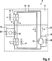
Die
Der erste geschlossene Kühlmittelkreislauf
Der zweite geschlossene Kühlmittelkreislauf
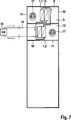
Das Kühlgerät
In den
Das Kühlgerät
Wie
Insbesondere bei hohen Umgebungstemperaturen kann es entsprechend dem Aufbau gemäß
Die
Die
Das zweite Kühlmittel in dem zweiten Kühlmittelkreislauf
Claims (12)
Priority Applications (14)
| Application Number | Priority Date | Filing Date | Title |
|---|---|---|---|
| DE102012108109.3A DE102012108109B4 (en) | 2012-08-31 | 2012-08-31 | Heat exchanger for cabinet cooling and a corresponding cooling arrangement |
| ES13759432T ES2699300T3 (en) | 2012-08-31 | 2013-08-23 | Heat exchanger for cooling a distribution booth and corresponding cooling system |
| CA2882605A CA2882605C (en) | 2012-08-31 | 2013-08-23 | Heat exchanger for cooling a switch cabinet and corresponding cooling arrangement |
| RU2015111336A RU2660812C2 (en) | 2012-08-31 | 2013-08-23 | Heat exchanger for cooling switch cabinet and corresponding cooling arrangement |
| JP2015528873A JP6184498B2 (en) | 2012-08-31 | 2013-08-23 | Cooling equipment corresponding to heat exchanger for cooling switch cabinet |
| IN1641DEN2015 IN2015DN01641A (en) | 2012-08-31 | 2013-08-23 | |
| MX2015001964A MX343679B (en) | 2012-08-31 | 2013-08-23 | Heat exchanger for cooling a switch cabinet and corresponding cooling arrangement. |
| EP13759432.1A EP2891397B1 (en) | 2012-08-31 | 2013-08-23 | Heat exchanger for cooling a switch cabinet and corresponding cooling arrangement |
| US14/392,021 US10375860B2 (en) | 2012-08-31 | 2013-08-23 | Heat exchanger for cooling a switch cabinet and corresponding cooling arrangement |
| CN201380048371.0A CN104813757B (en) | 2012-08-31 | 2013-08-23 | Cooling device with switchgear and cooling equipment |
| KR1020157005549A KR101769220B1 (en) | 2012-08-31 | 2013-08-23 | Heat exchanger for cooling a switch cabinet and corresponding cooling arrangement |
| BR112015003768-2A BR112015003768B1 (en) | 2012-08-31 | 2013-08-23 | refrigeration arrangement with a switch cabinet and refrigeration equipment |
| TR2019/00470T TR201900470T4 (en) | 2012-08-31 | 2013-08-23 | Heat exchanger and a corresponding cooling arrangement for the cooling of a switch cabinet. |
| PCT/DE2013/100306 WO2014032654A1 (en) | 2012-08-31 | 2013-08-23 | Heat exchanger for cooling a switch cabinet and corresponding cooling arrangement |
Applications Claiming Priority (1)
| Application Number | Priority Date | Filing Date | Title |
|---|---|---|---|
| DE102012108109.3A DE102012108109B4 (en) | 2012-08-31 | 2012-08-31 | Heat exchanger for cabinet cooling and a corresponding cooling arrangement |
Publications (2)
| Publication Number | Publication Date |
|---|---|
| DE102012108109A1 DE102012108109A1 (en) | 2014-03-06 |
| DE102012108109B4 true DE102012108109B4 (en) | 2014-04-10 |
Family
ID=49123613
Family Applications (1)
| Application Number | Title | Priority Date | Filing Date |
|---|---|---|---|
| DE102012108109.3A Active DE102012108109B4 (en) | 2012-08-31 | 2012-08-31 | Heat exchanger for cabinet cooling and a corresponding cooling arrangement |
Country Status (14)
| Country | Link |
|---|---|
| US (1) | US10375860B2 (en) |
| EP (1) | EP2891397B1 (en) |
| JP (1) | JP6184498B2 (en) |
| KR (1) | KR101769220B1 (en) |
| CN (1) | CN104813757B (en) |
| BR (1) | BR112015003768B1 (en) |
| CA (1) | CA2882605C (en) |
| DE (1) | DE102012108109B4 (en) |
| ES (1) | ES2699300T3 (en) |
| IN (1) | IN2015DN01641A (en) |
| MX (1) | MX343679B (en) |
| RU (1) | RU2660812C2 (en) |
| TR (1) | TR201900470T4 (en) |
| WO (1) | WO2014032654A1 (en) |
Families Citing this family (17)
| Publication number | Priority date | Publication date | Assignee | Title |
|---|---|---|---|---|
| DE102013110670A1 (en) | 2013-09-26 | 2015-03-26 | Rittal Gmbh & Co. Kg | cabinet system |
| DE102014102605A1 (en) | 2014-02-27 | 2015-08-27 | Windmöller & Hölscher Kg | Suction nozzle for a suction device |
| WO2016157818A1 (en) * | 2015-03-31 | 2016-10-06 | パナソニックIpマネジメント株式会社 | Cooling device |
| CN105813437B (en) * | 2016-03-21 | 2018-01-09 | 何祉欣 | A kind of sealed electrical control cubicles heat-exchanger rig of precision machine tool class |
| CN105953275A (en) * | 2016-06-21 | 2016-09-21 | 徐州工程学院 | Energy-saving water heating device |
| US11255611B2 (en) * | 2016-08-02 | 2022-02-22 | Munters Corporation | Active/passive cooling system |
| EP3312879A1 (en) * | 2016-10-20 | 2018-04-25 | Siemens Aktiengesellschaft | Cooling device for cooling electric and/or electronic devices arranged within a closed housing |
| DE102016121825A1 (en) * | 2016-11-14 | 2018-05-17 | Rittal Gmbh & Co. Kg | Chiller with compression refrigerant circuit and buffer memory, a corresponding cooling arrangement and a corresponding operating method |
| US20190168582A1 (en) * | 2017-12-01 | 2019-06-06 | Carrier Corporation | Multi-temperature transportation refrigeration system |
| KR101955997B1 (en) | 2018-02-23 | 2019-03-08 | 주식회사 에어메이저 | Hybrid Temperature And Humidity Control System For Control Panel Using Heat Pipe |
| JP2020063874A (en) * | 2018-10-17 | 2020-04-23 | 株式会社リコー | Condenser, loop type heat pipe, cooling device and electronic equipment |
| RU2729533C1 (en) * | 2018-12-06 | 2020-08-07 | Дмитрий Валерьевич Хачатуров | Electrotechnical device cabinet with liquid cooling system |
| CN109688766A (en) * | 2018-12-27 | 2019-04-26 | 广东海悟科技有限公司 | A kind of Novel cabinet air-conditioning |
| EP3723462B1 (en) | 2019-04-09 | 2022-06-22 | Pfannenberg GmbH | Cooling system, in particular for electronics cabinets, and electronics cabinet with a cooling system |
| EP3723461B1 (en) * | 2019-04-09 | 2021-04-07 | Pfannenberg GmbH | Cooling system and method for cooling an electronics cabinet |
| DE202019003326U1 (en) | 2019-08-09 | 2020-11-11 | Zweicom-Hauff Gmbh | Distribution cabinet |
| US11342731B1 (en) | 2021-01-19 | 2022-05-24 | Peopleflo Manufacturing, Inc. | Electrical control panel with cooling system |
Citations (5)
| Publication number | Priority date | Publication date | Assignee | Title |
|---|---|---|---|---|
| US6039111A (en) * | 1997-02-14 | 2000-03-21 | Denso Corporation | Cooling device boiling and condensing refrigerant |
| US6053238A (en) * | 1998-10-30 | 2000-04-25 | International Business Machines Corporation | Center feed parallel flow cold plate for dual refrigeration systems |
| DE20008411U1 (en) * | 2000-05-10 | 2000-07-27 | Roland Man Druckmasch | Unit cabinet for a printing machine |
| DE102007054724A1 (en) * | 2007-11-14 | 2009-05-28 | KKT KRAUS Kälte- und Klimatechnik GmbH | Installation cabinet for receiving electrical or electronic devices, in particular of computing devices, and device comprising a plurality of such installation cabinets, and method for operating such a device |
| DE102008059023A1 (en) * | 2008-11-26 | 2010-06-02 | Rittal Gmbh & Co. Kg | Air-conditioning device for electric control cabinet, has two independent cooling water channels which are provided in air-water-heat exchanger, where cooling water channels are connected to separate cooling water circuits |
Family Cites Families (25)
| Publication number | Priority date | Publication date | Assignee | Title |
|---|---|---|---|---|
| DE2423440C2 (en) * | 1974-05-14 | 1982-03-04 | Süddeutsche Kühlerfabrik Julius Fr. Behr GmbH & Co KG, 7000 Stuttgart | Internal combustion engine multi-circuit cooler block |
| DE3433598A1 (en) * | 1984-09-13 | 1986-03-20 | Heinz Schilling KG, 4152 Kempen | METHOD FOR PRACTICAL USE OF THE COUNTERFLOW PRINCIPLE FOR HEAT EXCHANGER, AIR / WATER, AIR / AIR OR SENSUAL MEASUREMENT FOR OTHER MEDIA |
| JPS62252889A (en) * | 1986-04-24 | 1987-11-04 | Matsushita Electric Works Ltd | Heat exchanger |
| RU2072490C1 (en) * | 1993-05-24 | 1997-01-27 | Физико-энергетический институт | Sectional plate heat exchanger |
| DE19540297C2 (en) * | 1995-10-28 | 1997-09-04 | Loh Kg Rittal Werk | Air-water heat exchanger for a control cabinet |
| US6119767A (en) * | 1996-01-29 | 2000-09-19 | Denso Corporation | Cooling apparatus using boiling and condensing refrigerant |
| JP3861361B2 (en) * | 1997-03-19 | 2006-12-20 | 株式会社デンソー | COOLING DEVICE AND CASE COOLING DEVICE HAVING THE COOLING DEVICE |
| JP2001085883A (en) * | 1999-09-17 | 2001-03-30 | Fuji Electric Co Ltd | Device for cooling electronics |
| US6761212B2 (en) * | 2000-05-25 | 2004-07-13 | Liebert Corporation | Spiral copper tube and aluminum fin thermosyphon heat exchanger |
| JP2003289195A (en) * | 2002-03-28 | 2003-10-10 | Mitsubishi Electric Corp | Cooling device |
| US7032411B2 (en) * | 2002-08-23 | 2006-04-25 | Global Energy Group, Inc. | Integrated dual circuit evaporator |
| JP4577188B2 (en) * | 2005-11-04 | 2010-11-10 | 株式会社デンソー | Cooling system |
| RU2433894C2 (en) * | 2006-01-19 | 2011-11-20 | Модайн Мэньюфэкчеринг Компани | Flat tube, heat exchanger of flat tubes and method of their manufacturing |
| CN100462159C (en) * | 2006-07-04 | 2009-02-18 | 陈世明 | Vertical combined type heat transfer radiating device manufacturing method |
| US7805955B2 (en) * | 2006-12-30 | 2010-10-05 | Intel Corporation | Using refrigeration and heat pipe for electronics cooling applications |
| CN201115243Y (en) * | 2007-08-24 | 2008-09-10 | 讯凯国际股份有限公司 | Combined heat radiation module structure and its fixing rack |
| JP4946930B2 (en) * | 2008-03-18 | 2012-06-06 | パナソニック株式会社 | AIR CONDITIONER AND STORAGE DEVICE PROVIDED WITH IT |
| DE102008049896A1 (en) * | 2008-10-03 | 2010-04-08 | Solarhybrid Ag | Lamella air heat exchanger for use in air heat pump for receiving heat energy from ambient air, comprises multiple lamellae and pipeline, where another pipeline runs separately from former pipeline which is guided through lamellae |
| US8117857B2 (en) * | 2009-02-20 | 2012-02-21 | Tesla Motors, Inc. | Intelligent temperature control system for extending battery pack life |
| DE102010009776B4 (en) | 2010-03-01 | 2014-01-02 | Rittal Gmbh & Co. Kg | Method and device for controlling a mounted in or on a cabinet refrigerator |
| JP2012009646A (en) * | 2010-06-25 | 2012-01-12 | Panasonic Corp | Cooling device and electronic apparatus using the same |
| US20140109603A1 (en) * | 2011-12-29 | 2014-04-24 | Embraer S.A. | Integrated environmental control systems and methods for controlling environmental temperature of an enclosed space |
| US20140260389A1 (en) * | 2013-03-15 | 2014-09-18 | Ramana Venkato Rao Sistla | Refrigerant Flow Control for an Evaporative Atmospheric Water Condenser |
| US20140262188A1 (en) * | 2013-03-15 | 2014-09-18 | Ramana Venkato Rao Sistla | Fin Spacing On An Evaporative Atmospheric Water Condenser |
| CA2871440C (en) * | 2013-12-03 | 2021-01-19 | Modine Manufacturing Company | Furnace and method for heating air |
-
2012
- 2012-08-31 DE DE102012108109.3A patent/DE102012108109B4/en active Active
-
2013
- 2013-08-23 EP EP13759432.1A patent/EP2891397B1/en active Active
- 2013-08-23 KR KR1020157005549A patent/KR101769220B1/en active IP Right Grant
- 2013-08-23 CA CA2882605A patent/CA2882605C/en active Active
- 2013-08-23 ES ES13759432T patent/ES2699300T3/en active Active
- 2013-08-23 US US14/392,021 patent/US10375860B2/en active Active
- 2013-08-23 TR TR2019/00470T patent/TR201900470T4/en unknown
- 2013-08-23 JP JP2015528873A patent/JP6184498B2/en active Active
- 2013-08-23 MX MX2015001964A patent/MX343679B/en active IP Right Grant
- 2013-08-23 IN IN1641DEN2015 patent/IN2015DN01641A/en unknown
- 2013-08-23 CN CN201380048371.0A patent/CN104813757B/en active Active
- 2013-08-23 RU RU2015111336A patent/RU2660812C2/en active
- 2013-08-23 WO PCT/DE2013/100306 patent/WO2014032654A1/en active Application Filing
- 2013-08-23 BR BR112015003768-2A patent/BR112015003768B1/en active IP Right Grant
Patent Citations (5)
| Publication number | Priority date | Publication date | Assignee | Title |
|---|---|---|---|---|
| US6039111A (en) * | 1997-02-14 | 2000-03-21 | Denso Corporation | Cooling device boiling and condensing refrigerant |
| US6053238A (en) * | 1998-10-30 | 2000-04-25 | International Business Machines Corporation | Center feed parallel flow cold plate for dual refrigeration systems |
| DE20008411U1 (en) * | 2000-05-10 | 2000-07-27 | Roland Man Druckmasch | Unit cabinet for a printing machine |
| DE102007054724A1 (en) * | 2007-11-14 | 2009-05-28 | KKT KRAUS Kälte- und Klimatechnik GmbH | Installation cabinet for receiving electrical or electronic devices, in particular of computing devices, and device comprising a plurality of such installation cabinets, and method for operating such a device |
| DE102008059023A1 (en) * | 2008-11-26 | 2010-06-02 | Rittal Gmbh & Co. Kg | Air-conditioning device for electric control cabinet, has two independent cooling water channels which are provided in air-water-heat exchanger, where cooling water channels are connected to separate cooling water circuits |
Also Published As
| Publication number | Publication date |
|---|---|
| DE102012108109A1 (en) | 2014-03-06 |
| CN104813757A (en) | 2015-07-29 |
| BR112015003768A2 (en) | 2017-07-04 |
| US10375860B2 (en) | 2019-08-06 |
| US20150163956A1 (en) | 2015-06-11 |
| CA2882605C (en) | 2019-07-16 |
| IN2015DN01641A (en) | 2015-07-03 |
| CN104813757B (en) | 2018-09-11 |
| ES2699300T3 (en) | 2019-02-08 |
| CA2882605A1 (en) | 2014-03-06 |
| KR101769220B1 (en) | 2017-08-17 |
| EP2891397B1 (en) | 2018-10-17 |
| BR112015003768B1 (en) | 2021-05-11 |
| TR201900470T4 (en) | 2019-02-21 |
| RU2660812C2 (en) | 2018-07-10 |
| MX2015001964A (en) | 2015-09-28 |
| RU2015111336A (en) | 2016-10-20 |
| JP2015529977A (en) | 2015-10-08 |
| JP6184498B2 (en) | 2017-08-23 |
| EP2891397A1 (en) | 2015-07-08 |
| MX343679B (en) | 2016-11-17 |
| KR20150052055A (en) | 2015-05-13 |
| WO2014032654A1 (en) | 2014-03-06 |
Similar Documents
| Publication | Publication Date | Title |
|---|---|---|
| DE102012108109B4 (en) | Heat exchanger for cabinet cooling and a corresponding cooling arrangement | |
| DE102012108110B4 (en) | Cooling arrangement for arranged in an interior of a cabinet components | |
| DE102006005035B3 (en) | cooling system | |
| EP1876402A2 (en) | Heat pump with temperature control unit | |
| EP3648997B1 (en) | Refrigeration system for a vehicle, comprising a refrigerant circuit having a heat exchanger, and heat exchanger for such a refrigeration system | |
| EP2026019A2 (en) | Tempering unit on a heat pump basis | |
| EP1616133A1 (en) | Combined fluid-air evaporator and novel switching concept for a heat pump in a ventilating apparatus | |
| EP1576321A2 (en) | Refrigerant circuit and a refrigerating system | |
| DE102019200673A1 (en) | Refrigerator with automatically defrostable evaporator | |
| DE102012108108B4 (en) | Control cabinet with a cooling unit for passive cabinet cooling | |
| DE102018215026B4 (en) | Refrigeration system for a vehicle with a refrigerant circuit having a double-flow heat exchanger, as well as heat exchangers and a method for operating the refrigeration system | |
| DE202011102503U1 (en) | heat pump system | |
| EP3682179B1 (en) | Cold generator and refrigerating plant having a cold generator | |
| DE102019200859A1 (en) | Refrigerator | |
| DE102019202649A1 (en) | Refrigeration device | |
| AT517021B1 (en) | Heat exchange equipment | |
| DE10215587B4 (en) | Device for freezing a heat exchanger apparatus | |
| EP2674698A1 (en) | Heat pump assembly | |
| WO2016206816A1 (en) | Device and method for deicing a heat exchanger in evaporator operation of a cooling system and vehicle having such a device | |
| DE202009016879U1 (en) | heat exchangers | |
| DE102016121825A1 (en) | Chiller with compression refrigerant circuit and buffer memory, a corresponding cooling arrangement and a corresponding operating method | |
| DE102015221322A1 (en) | Apparatus and method for cooling a hydraulic fluid and hydraulic circuit with the cooling device | |
| DE102012020928A1 (en) | Heat pump device installed in building, has valves that are switched between two switching positions in which capacitor and vaporizer are fluidly coupled in countercurrent with indoor and outdoor heat exchangers alternatively | |
| DE102011084826A1 (en) | Cold apparatus e.g. household cold apparatus, for e.g. storing food and/or beverages at certain temperature in e.g. home, has valve selectively connecting supply line to vaporizer or another valve and outlet with compressor | |
| DE102017107394A1 (en) | heat pump system |
Legal Events
| Date | Code | Title | Description |
|---|---|---|---|
| R012 | Request for examination validly filed | ||
| R016 | Response to examination communication | ||
| R016 | Response to examination communication | ||
| R016 | Response to examination communication | ||
| R018 | Grant decision by examination section/examining division | ||
| R020 | Patent grant now final | ||
| R020 | Patent grant now final |
Effective date: 20150113 |