DE102012105992A1 - Element of an electrical machine with a holder and a permanent magnet, component with at least one element and an electric machine - Google Patents
Element of an electrical machine with a holder and a permanent magnet, component with at least one element and an electric machine Download PDFInfo
- Publication number
- DE102012105992A1 DE102012105992A1 DE102012105992A DE102012105992A DE102012105992A1 DE 102012105992 A1 DE102012105992 A1 DE 102012105992A1 DE 102012105992 A DE102012105992 A DE 102012105992A DE 102012105992 A DE102012105992 A DE 102012105992A DE 102012105992 A1 DE102012105992 A1 DE 102012105992A1
- Authority
- DE
- Germany
- Prior art keywords
- holder
- rotor
- face
- permanent magnet
- rotor hub
- Prior art date
- Legal status (The legal status is an assumption and is not a legal conclusion. Google has not performed a legal analysis and makes no representation as to the accuracy of the status listed.)
- Withdrawn
Links
Images


Classifications
-
- H—ELECTRICITY
- H02—GENERATION; CONVERSION OR DISTRIBUTION OF ELECTRIC POWER
- H02K—DYNAMO-ELECTRIC MACHINES
- H02K1/00—Details of the magnetic circuit
- H02K1/06—Details of the magnetic circuit characterised by the shape, form or construction
- H02K1/22—Rotating parts of the magnetic circuit
- H02K1/27—Rotor cores with permanent magnets
- H02K1/2706—Inner rotors
- H02K1/272—Inner rotors the magnetisation axis of the magnets being perpendicular to the rotor axis
- H02K1/274—Inner rotors the magnetisation axis of the magnets being perpendicular to the rotor axis the rotor consisting of two or more circumferentially positioned magnets
- H02K1/2753—Inner rotors the magnetisation axis of the magnets being perpendicular to the rotor axis the rotor consisting of two or more circumferentially positioned magnets the rotor consisting of magnets or groups of magnets arranged with alternating polarity
- H02K1/276—Magnets embedded in the magnetic core, e.g. interior permanent magnets [IPM]
- H02K1/2766—Magnets embedded in the magnetic core, e.g. interior permanent magnets [IPM] having a flux concentration effect
- H02K1/2773—Magnets embedded in the magnetic core, e.g. interior permanent magnets [IPM] having a flux concentration effect consisting of tangentially magnetized radial magnets
Abstract
Erfindungsgemäß wird Element einer elektrischen Maschine mit einer Halterung, die eine erste Stirnfläche mit einem Verbindungsabschnitt zum Befestigen an einer Rotornabe und eine zweite Stirnfläche aufweist, und wenigstens einen in Umfangsrichtung der elektrischen Maschine magnetisierten Permanentmagneten, welcher in eine Tasche der Halterung eingesetzt ist, vorgeschlagen, wobei die zweite Stirnfläche eine Vertiefung bei dem wenigstens einen Permanentmagnet aufweist, so dass die Ausbildung des magnetischen Felds der Permanentmagneten optimiert wird.According to the invention, the element of an electrical machine is provided with a holder which has a first end face with a connection section for attachment to a rotor hub and a second end face, and at least one permanent magnet magnetized in the circumferential direction of the electric machine which is inserted into a pocket of the holder. wherein the second end face has a recess in the at least one permanent magnet, so that the formation of the magnetic field of the permanent magnet is optimized.
Description
Die Erfindung betrifft ein Element einer elektrischen Maschine mit einer Halterung, die eine erste Stirnfläche mit einem Verbindungsabschnitt zum Befestigen an einer Rotornabe und eine zweite Stirnfläche aufweist, und wenigstens einen in Umfangsrichtung der elektrischen Maschine magnetisierten Permanentmagneten, welcher in eine Tasche der Halterung eingesetzt ist. Ferner betrifft die Erfindung ein Bauteil einer elektrischen Maschine, insbesondere einen Rotor mit einer Rotornabe sowie eine elektrische Maschine.The invention relates to an element of an electrical machine with a holder, which has a first end face with a connecting portion for attachment to a rotor hub and a second end face, and at least one in the circumferential direction of the electric machine magnetized permanent magnet, which is inserted into a pocket of the holder. Furthermore, the invention relates to a component of an electrical machine, in particular a rotor with a rotor hub and an electric machine.
Ein solches Element ist bekannt aus der
Beim Bau von elektrischen Maschinen, insbesondere von Synchronmaschinen, können Permanentmagneten anstatt Spulen im Rotor und/oder im Stator verwendet werden. Der Stator bezeichnet dabei den ruhenden Teil und der Rotor den sich bewegenden Teil der elektrischen Maschine. Bekannte Materialien für die Herstellung von Permanentmagneten sind unter anderem Bismut-Mangan-Magnete, Aluminium-Nickel-Cobalt-Magnete, Samarium-Cobalt-Magnete und Neodym-Eisen-Bor-Magnete. Bei einer Synchronmaschine wird zwischen einem Außenläufer und einem Innenläufer unterschieden. Ein Innenläufer ist eine Bauform einer Synchronmaschine, bei der sich der Rotor im Zentrum befindet und der Stator den Rotor umschließt. Der Rotor weist bei einem Innenläufer im Allgemeinen eine Mehrzahl von abwechselnd radial ausgerichteten, ringförmig um die Rotorachse angeordneten Permanentmagneten auf, die sich entsprechend der Rotorachse auf einer kreisförmigen Bahn bewegen. Das magnetische Feld, das sich bei dieser Anordnung der Permanentmagneten ergibt, wird auch als Erregerfeld bezeichnet. Bei einer Bewegung der Permanentmagneten wird nunmehr aufgrund der ständigen Änderung der magnetischen Felder, die auf die Statorspulen wirken, in den Statorspulen eine Spannung induziert, wodurch im Generatorbetrieb der elektrischen Maschine ein elektrischer Strom in Abhängigkeit zur Bewegung des Rotors erzeugt wird.In the construction of electrical machines, in particular of synchronous machines, permanent magnets can be used instead of coils in the rotor and / or in the stator. The stator designates the stationary part and the rotor the moving part of the electric machine. Known materials for the production of permanent magnets include bismuth-manganese magnets, aluminum-nickel-cobalt magnets, samarium-cobalt magnets and neodymium-iron-boron magnets. In a synchronous machine, a distinction is made between an external rotor and an internal rotor. An internal rotor is a type of synchronous machine in which the rotor is in the center and the stator surrounds the rotor. In an internal rotor, the rotor generally has a plurality of alternately radially oriented, annularly arranged around the rotor axis permanent magnets, which move according to the rotor axis on a circular path. The magnetic field that results in this arrangement of permanent magnets is also referred to as exciter field. During a movement of the permanent magnets, a voltage is now induced in the stator coils due to the constant change of the magnetic fields which act on the stator coils, whereby an electric current is generated in generator operation of the electric machine in dependence on the movement of the rotor.
Die Permanentmagneten werden üblicherweise dergestalt an der Rotornabe des Rotors angeordnet, dass ihre Magnetisierungsrichtung bzw. Ausrichtung der Pole parallel zur Radialrichtung verläuft. Hierfür wurden für die Befestigung der Permanentmagneten bereits diverse Möglichkeiten in Betracht gezogen. Eine Möglichkeit ist es, die Magneten mittels speziell gefertigter Halterungen an der Rotornabe zu befestigen. Die Herausforderung ist dabei, dass die Rotorbleche während des Betriebs in Radialrichtung nicht nur die Fliehkräfte der Permanentmagneten aufnehmen müssen, sondern auch die Kräfte, die durch die magnetische Wechselwirkung zwischen den Permanentmagneten und den Statorspulen sowie auch anderen magnetischen Teilen des Rotors oder Stators entstehen. Es wirken also in Magnetisierungsrichtung der Permanentmagneten auf die Permanentmagneten selbst zusätzlich magnetische Kräfte, die die Rotorbleche aufnehmen müssen. Aus diesem Grund müssen die Rotorbleche massiv und stabil ausgebildet werden, um den angesprochenen Kräften Rechnung zu tragen. Meist werden die Permanentmagneten in Aussparungen des Rotorblechs eingesetzt, wodurch sich zwischen der Aussparung und dem Luftspalt zum Stator hin ein Steg erstreckt. Die Aufgabe dieser Stege ist es, die Kräfte in Radialrichtung aufzunehmen. Weiter ist der magnetische Widerstand des Stegs generell nicht groß und zudem umso kleiner, je breiter dieser ist. Dieser Steg muss zur Gewährleistung einer ausreichenden mechanischen Festigkeit einerseits umso breiter gestaltet sein, je größer das magnetische Feld, das Gewicht des Permanentmagneten und die Drehzahl des Rotors ist, um eine ausreichende mechanische Festigkeit gewährleisten zu können, andererseits aber möglichst schmal gestaltet sein, da dieser sonst einen erheblichen Anteil des magnetischen Flusses der Permanentmagneten aufgrund seines niedrigen magnetischen Widerstands kurzschließen würde und demzufolge das auf die Statorspulen wirkende, verbleibende magnetische Feld erheblich schwachen würde. In anderen Worten bedeutet dies, dass der Steg möglichst schmal sein sollte, damit er einen größeren magnetischen Widerstand aufweist und damit die effektive Erregerflussdichte größer ist. Die Effizienz der elektrischen Maschine wird nun maßgeblich durch die effektive Erregerflussdichte und damit durch die Breite des Stegs beeinflusst. Insofern besteht ein wesentliches Problem darin, die Breite des Steges zu verschmälern, während gleichzeitig eine ausreichende mechanische Stabilität und eine geeignete Verteilung der Flussdichte gewährleistet sind. Darüber hinaus ist die Gestaltung der Rotorbleche, insbesondere im Verbindungsabschnitt, mit Blick auf die Flussdichte nachteilhaft.The permanent magnets are usually arranged on the rotor hub of the rotor in such a way that its magnetization direction or orientation of the poles runs parallel to the radial direction. For this purpose, various possibilities have already been considered for the attachment of permanent magnets. One possibility is to attach the magnets to the rotor hub using specially manufactured brackets. The challenge is that the rotor laminations during operation in the radial direction not only have to absorb the centrifugal forces of the permanent magnets, but also the forces resulting from the magnetic interaction between the permanent magnets and the stator coils and other magnetic parts of the rotor or stator. Thus, in the direction of magnetization of the permanent magnets, magnetic forces, which must be absorbed by the rotor laminations, additionally act on the permanent magnets themselves. For this reason, the rotor laminations must be made massive and stable in order to take account of the forces mentioned. Most permanent magnets are used in recesses of the rotor plate, which extends between the recess and the air gap to the stator through a web. The task of these webs is to absorb the forces in the radial direction. Furthermore, the magnetic resistance of the web is generally not large and, in addition, the smaller, the wider it is. To ensure adequate mechanical strength, this web must on the one hand be designed to be wider, the larger the magnetic field, the weight of the permanent magnet and the rotational speed of the rotor, in order to ensure sufficient mechanical strength, but on the other hand designed to be as narrow as possible otherwise it would short circuit a significant portion of the magnetic flux of the permanent magnets due to its low magnetic resistance, and consequently the residual magnetic field acting on the stator coils would be significantly weakened. In other words, this means that the web should be as narrow as possible, so that it has a greater magnetic resistance and thus the effective excitation flux density is greater. The efficiency of the electrical machine is now significantly influenced by the effective excitation flux density and thus by the width of the web. In this respect, a major problem is to narrow the width of the web, while at the same time a sufficient mechanical stability and a suitable distribution of the flux density are ensured. In addition, the design of the rotor laminations, in particular in the connecting portion, in view of the flux density is disadvantageous.
Ein weiterer Ansatz, um dieses Problem zu lösen, besteht darin, die in Erstreckungsrichtung magnetisierten Permanentmagneten unter einer V-Anordnung im Rotorblech angeordnet sind, wie dies aus der
Dementsprechend ist es Aufgabe der vorliegenden Erfindung Permanentmagneten mit in Umfangsrichtung ausgerichtete Pole mit einer Halterung so zu halten, dass die Ausbildung des magnetischen Felds der Permanentmagneten optimiert wird.Accordingly, it is an object of the present invention to hold permanent magnets with circumferentially oriented poles with a holder so that the formation of the magnetic field of the permanent magnet is optimized.
Diese Aufgabe wird durch ein Element einer elektrischen Maschine mit einer Halterung und wenigstens einem Permanentmagneten mit den Merkmalen des Anspruchs 1 gelöst.This object is achieved by an element of an electric machine with a holder and at least one permanent magnet having the features of
Erfindungsgemäß wird ein Element einer elektrischen Maschine mit einer Halterung, die eine erste Stirnfläche mit einem Verbindungsabschnitt zum Befestigen an einer Rotornabe und eine zweite Stirnfläche aufweist, und wenigstens einen in Umfangsrichtung der elektrischen Maschine magnetisierten Permanentmagneten, welcher in eine Tasche der Halterung eingesetzt ist, vorgeschlagen, wobei die zweite Stirnfläche eine Vertiefung bei dem wenigstens einen Permanentmagnet aufweist.According to the invention, an element of an electrical machine with a holder, which has a first end face with a connection section for attachment to a rotor hub and a second end face, and at least one magnet magnetized in the circumferential direction of the permanent magnet, which is inserted into a pocket of the holder, is proposed wherein the second end face has a recess in the at least one permanent magnet.
Zweck einer solchen Vertiefung der zweiten Stirnfläche ist, dass im radialen Bereich zwischen dem wenigstens einem Permanentmagneten und dem Luftspalt zwischen Rotor und Stator möglichst wenig Material der Halterung ausgebildet ist, so dass dieser Bereich den magnetischen Fluss der Permanentmagneten nur geringfügig kurzschließt. Weiter wird mit der Formgebung der Vertiefung die Breite des Luftspalts zwischen Stator und Rotor definiert. Je breiter der Spalt, umso höher ist der magnetische Widerstand an dieser Stelle. So kommt der Formgebung des Übergangs zwischen der Vertiefung und der tatsächlichen zweiten Stirnfläche der Halterung eine entscheidende Bedeutung zu, denn dadurch kann die Charakteristik des magnetischen Feldes bzw. die Verteilung der Flussdichte im Spalt präzise festgelegt werden. Somit kann beispielsweise den Schwerpunkt der magnetischen Flussdichte auf eine geeignete Position beschränkt werden.The purpose of such a recess of the second end face is that in the radial area between the at least one permanent magnet and the air gap between the rotor and stator as little as possible material of the holder is formed, so that this area short circuits the magnetic flux of the permanent magnets only slightly. Further, the shape of the recess defines the width of the air gap between the stator and the rotor. The wider the gap, the higher the magnetic resistance at this point. Thus, the shaping of the transition between the recess and the actual second end face of the holder is of crucial importance, because thereby the characteristic of the magnetic field or the distribution of the flux density in the gap can be precisely determined. Thus, for example, the center of gravity of the magnetic flux density can be restricted to an appropriate position.
Dadurch, dass der wenigstens eine Permanentmagnet in eine Tasche eingesetzt ist, hält die Halterung den Permanentmagneten derart fest, dass er sich aufgrund der in der Maschine wirkenden Kräfte nicht aus der Halterung löst. In diesem Zusammenhang kann wirkungsvoll vermieden werden, dass sich die Permanentmagneten von der Rotornabe des Rotors lösen bzw. unbeabsichtigt bewegen und einen zwischen dem Rotor und einem Stator vorliegenden Luftspalt verkleinern oder sogar den Stator berühren, so dass die Permanentmagneten die elektrische Maschine zerstören.Characterized in that the at least one permanent magnet is inserted into a pocket, the holder holds the permanent magnet so firmly that it does not detach from the holder due to the forces acting in the machine. In this connection, it can be effectively avoided that the permanent magnets detach from the rotor hub of the rotor or move inadvertently and reduce an air gap existing between the rotor and a stator, or even touch the stator, so that the permanent magnets destroy the electric machine.
Mittels der Magnetisierungsrichtung der Permanentmagneten in Umfangsrichtung der elektrischen Maschine kann die Halterung dergestalt ausgebildet sein, dass sich die Halterung nicht zwischen dem wenigstens einem Permanentmagneten und dem Luftspalt erstreckt. Die Vertiefung geht dabei in die den wenigstens einen Permanentmagneten aufnehmende Tasche über. So kann der geschlossene Pfad des magnetischen Flusses der Permanentmagneten bzw. der magnetische Kreis in Richtung der Statorspulen stärker sein, da aufgrund des höheren magnetischen Widerstands des ersten Stegs der magnetische Fluss der Permanentmagneten durch die Halterung nicht kurzgeschlossen wird. Die vorteilhafte Ausgestaltung der Halterung führt weiter zu einer verbesserten Flussdichteverteilung, wodurch ein höherer Wirkungsgrad der elektrischen Maschine erreicht wird. Da sich die Permanentmagneten in Radialrichtung des Rotors erstrecken und so die größten Flächen der Permanentmagneten parallel zur Radialrichtung sind, können diese Flächen der Permanentmagneten mit den radial erstreckenden Flächen der Tasche besonders gut mit Klebstoff, Haftmittel, usw. verklebt werden. Dadurch werden die bei der Rotation auftretenden Fliehkräfte als Schubkräfte von der Klebverbindung zwischen Permanentmagnet und Halterung übertragen. Schubspannungen können von Klebstoffen, usw. in der Regel besser als Normalkräfte übertragen werden. Demnach wird die Sicherheit gegen Versagen der Klebverbindung wesentlich erhöht.By means of the magnetization direction of the permanent magnets in the circumferential direction of the electric machine, the holder may be designed such that the holder does not extend between the at least one permanent magnet and the air gap. The recess goes over into the at least one permanent magnet receiving pocket. Thus, the closed path of the magnetic flux of the permanent magnet or the magnetic circuit in the direction of the stator coils may be stronger, since due to the higher magnetic resistance of the first land, the magnetic flux of the permanent magnet is not short-circuited by the holder. The advantageous embodiment of the holder further leads to an improved flux density distribution, whereby a higher efficiency of the electric machine is achieved. Since the permanent magnets extend in the radial direction of the rotor and so the largest surfaces of the permanent magnets are parallel to the radial direction, these surfaces of the permanent magnets with the radially extending surfaces of the pocket can be particularly well bonded with adhesive, adhesive, etc. As a result, the centrifugal forces occurring during rotation are transmitted as thrust forces from the adhesive bond between the permanent magnet and the holder. Shear stresses can be transmitted by adhesives, etc., usually better than normal forces. Accordingly, the security against failure of the adhesive bond is substantially increased.
Dadurch, dass die Ausrichtung der Pole des wenigstens einen Permanentmagneten in Umfangsrichtung verläuft, wirken auf den wenigstens einen Permanentmagneten beim Betrieb der elektrischen Maschine keine magnetischen Kräfte in Radialrichtung, so dass die Halterung in Radialrichtung lediglich die auf die Permanentmagneten wirkenden Fliehkräfte aufnehmen muss, während die verbleibenden magnetischen Kräfte in Umfangsrichtung von der Halterung aufgrund deren Orientierung einfacher aufgenommen werden können.Because the orientation of the poles of the at least one permanent magnet extends in the circumferential direction, no magnetic forces in the radial direction act on the at least one permanent magnet during operation of the electrical machine, so that the holder only has to absorb the centrifugal forces acting on the permanent magnets during the radial direction remaining magnetic forces in the circumferential direction of the holder due to their orientation can be easily absorbed.
Nach dem Einsetzen des wenigstens einen Permanentmagneten in die Tasche, kann dieser zusätzlich noch mittels eines Klebstoffs oder eines Haftmittels in der Tasche befestigt werden. After inserting the at least one permanent magnet in the pocket, this can additionally be secured by means of an adhesive or an adhesive in the bag.
Zusätzlich oder alternativ können die erste Stirnfläche und die zweite Stirnfläche durch zwei wenigstens abschnittsweise, vorzugsweise radial, nach innen gekrümmte Seitenflächen verbunden sein. Die zweite Stirnfläche der Halterung erstreckt sich im Bereich des Luftspalts zwischen dem Rotor und dem Stator, d. h. von der Rotornabe abgewandt. Mittels der nach innen gekrümmten Seitenflächen wird die Halterung so ausgebildet, dass sie von der zweiten Stirnfläche zu der ersten Stirnfläche trichterförmig bzw. trompetenförmig zusammenläuft. So kann im Bereich des Verbindungsabschnitts, d. h. an der Rotornabe, zwischen zwei in Umfangsrichtung des Rotors benachbarten Elementen ein wesentlich größerer Abstand ausgebildet sein als ein Abstand im Bereich der zweiten Stirnfläche. Durch den wesentlich größeren Abstand im Bereich des Verbindungsabschnitts zwischen den zwei in Umfangsrichtung des Rotors benachbarten Elementen herrscht in diesem Bereich aufgrund von Luft ein großer magnetischer Widerstand, wohingegen im Bereich, bei dem der Abstand im Bereich des Luftspalts zwischen Rotor und Stator zwischen den zwei in Umfangsrichtung des Rotors benachbarten Elementen geringer ist und somit wesentlich mehr ferromagnetisches Material der Halterung vorhanden ist, ein niedrigerer magnetischer Widerstand vorliegt. Hierbei kann wirkungsvoll der magnetische Fluss des wenigstens einen Permanentmagneten einer Halterung in Richtung Luftspalt zwischen Rotor und Stator bereitgestellt werden und somit der Wirkungsgrad der elektrischen Maschine wesentlich erhöht werden. Es wird dem magnetischen Feld also eine Vorzugsrichtung vorgegeben, wobei die Formgebung der Stirnflächen die Flussdichteverteilung in Richtung des Luftspalts maßgeblich beeinflusst. Neben dieser Form ist weiter das Verhältnis aus Höhe und Breite der Halterung für diese Flussdichteverteilung entscheidend. Darüber hinaus begrenzt diese erläuterte Form der Halterung wesentlich die Ankerrückwirkung in der Halterung, da der von den Statorströmen erzeugte Ankerfeldanregung ein großer magnetischer Widerstand entgegenwirkt, wodurch der Wirkungsgrad der elektrischen Maschine positiv beeinflusst wird. Darüber hinaus kann durch diese Formgestaltung der Halterung eine große Gewichtseinsparung durch Materialeinsparung erzielt werden.Additionally or alternatively, the first end face and the second end face may be connected by two side faces curved at least in sections, preferably radially, inwardly. The second end face of the holder extends in the region of the air gap between the rotor and the stator, d. H. turned away from the rotor hub. By means of the inwardly curved side surfaces, the holder is formed so that it converges in a funnel shape or trumpet shape from the second end face to the first end face. Thus, in the area of the connection section, i. H. on the rotor hub, between two elements which are adjacent in the circumferential direction of the rotor, a substantially greater distance may be formed than a distance in the region of the second end face. Due to the much larger distance in the region of the connecting portion between the two adjacent circumferentially of the rotor elements prevails in this area due to air, a large magnetic resistance, whereas in the area in which the distance in the air gap between the rotor and stator between the two in Circumferential direction of the rotor adjacent elements is lower and thus significantly more ferromagnetic material of the holder is present, a lower magnetic resistance is present. In this case, the magnetic flux of the at least one permanent magnet of a holder in the direction of the air gap between the rotor and the stator can be effectively provided and thus the efficiency of the electric machine can be substantially increased. Thus, a preferred direction is given to the magnetic field, wherein the shaping of the end faces decisively influences the flux density distribution in the direction of the air gap. In addition to this shape, the ratio of the height and width of the holder for this flux density distribution is crucial. In addition, this illustrated form of the bracket substantially limits the armature reaction in the bracket because the armature field excitation generated by the stator currents counteracts large magnetic resistance, thereby positively affecting the efficiency of the electric machine. In addition, a large weight saving can be achieved by saving material by this shape design of the holder.
Gerade bei Synchronmaschinen, die große Durchmesser aufweisen können, sowie der Tatsache, dass die Halterungen im äußersten Bereich des Rotors angeordnet sind und dort die Fliehkräfte am stärksten wirken, ist diese Formgestaltung besonders gut, um die auf den Rotor wirkenden Fliehkräfte zu reduzieren. Einhergehend damit können die Bauteile, insbesondere die Halterung, mit Materialien ausgebildet sein, die eine geringere Festigkeit aufweisen. Vorteilhaft ist gleichfalls, dass aufgrund eines niedrigeren Trägheitsmoments der Rotor beim Betriebsbeginn schneller anläuft. Mittels einer derartigen Ausbildung der beiden Seitenflächen kann ferner der magnetische Fluss derart bereitgestellt werden, dass eine besonders gut angenäherte sinusförmige Stromkurve bei Drehung des Rotors erzeugt wird.Especially in synchronous machines, which can have large diameters, as well as the fact that the brackets are located in the outermost region of the rotor and where the centrifugal forces act most, this shape design is particularly good to reduce the forces acting on the rotor centrifugal forces. Along with this, the components, in particular the holder, may be formed with materials which have a lower strength. It is also advantageous that, due to a lower moment of inertia, the rotor starts up faster at the start of operation. By means of such a configuration of the two side surfaces, the magnetic flux can also be provided in such a way that a particularly well-approximated sinusoidal current curve is generated upon rotation of the rotor.
In einer bevorzugten Weiterbildung kann sich ein erster Steg parallel zur ersten Stirnfläche erstrecken. Indem sich der in Umfangsrichtung des Rotors magnetisierte Permanentmagnet radial erstreckt und in die Tasche eingesetzt ist, kann es jedoch vorkommen, dass sich die Halterung im Bereich der zweiten Stirnfläche unbeabsichtigt aufgrund der Fliehkräfte verformt. Um dem entgegenzuwirken, wird im Bereich zwischen Luftspalt und dem wenigstens einem Permanentmagnet ein erster Steg vorgesehen, welcher die Festigkeit und Stabilität der Halterung gewährleistet. Allerdings ist es vorteilhaft, den Steg möglichst schmal auszubilden, so dass dieser den magnetischen Fluss nur geringfügig kurzschließt. Ferner kann durch eine geeignete Länge des wenigstens einen Permanentmagneten in Radialrichtung die kurzschließende Wirkung des Permanentmagneten infolge des ersten Stegs kompensiert werden, da eine größere Länge in Summe einen größeren magnetischen Fluss des Permanentmagneten bedeutet.In a preferred embodiment, a first web may extend parallel to the first end face. Since the permanent magnet magnetized in the circumferential direction of the rotor extends radially and is inserted into the pocket, it may happen that the holder in the region of the second end face inadvertently deforms due to centrifugal forces. To counteract this, a first web is provided in the region between the air gap and the at least one permanent magnet, which ensures the strength and stability of the holder. However, it is advantageous to design the web as narrow as possible so that it only shorts the magnetic flux only slightly. Further, by a suitable length of the at least one permanent magnet in the radial direction, the short-circuiting effect of the permanent magnet due to the first land can be compensated because a larger length in total means a larger magnetic flux of the permanent magnet.
Zusätzlich oder alternativ kann die Halterung des erfindungsgemäßen Elements einen parallel zur ersten Stirnfläche erstreckenden zweiten Steg im Bereich des Verbindungsabschnitts aufweisen. Dadurch, dass das Material des Permanentmagneten und das Material der Halterung bei hohen Temperaturen unterschiedliche Ausdehnungskoeffizienten aufweisen, ist der zweite Steg im Bereich des Verbindungsabschnitts vorgesehen. So kann wirksam vermieden werden, dass sich die Permanentmagneten und/oder die Halterung von der Rotornabe lösen/löst. Weiterhin ist es vorteilhaft, den zweiten Steg ebenfalls relativ schmal auszubilden, so dass dieser den magnetischen Fluss nur zu einem geringen Anteil kurzschließt.Additionally or alternatively, the holder of the element according to the invention may have a second web extending parallel to the first end face in the region of the connecting portion. Characterized in that the material of the permanent magnet and the material of the holder at high temperatures have different coefficients of expansion, the second web is provided in the region of the connecting portion. Thus, it can be effectively avoided that the permanent magnet and / or the holder of the rotor hub solve / dissolves. Furthermore, it is advantageous to form the second web also relatively narrow, so that it short-circuits the magnetic flux only to a small extent.
Werden wenigstens zwei Permanentmagneten, die sich vorzugsweise radial nach der Montage der Halterung an der Rotornabe erstrecken, in der Tasche aufgenommen, kann die Tasche wenigstens eine quer zur ersten Stirnfläche erstreckende Speiche aufweisen. Mittels dieser wenigstens einen Speiche wird die mechanische Festigkeit der Halterung weiter verbessert.If at least two permanent magnets, which preferably extend radially after the mounting of the holder on the rotor hub, are received in the pocket, the pocket can have at least one spoke extending transversely to the first end face. By means of this at least one spoke, the mechanical strength of the holder is further improved.
Vorzugsweise kann die zweite Stirnfläche abschnittsweise nach außen gekrümmt bzw. gewölbt ausgebildet sein. Mittels einer derartigen Ausbildung der zweiten Stirnfläche kann der magnetische Fluss derart bereitgestellt werden, dass eine besonders gut angenäherte sinusförmige Stromkurve bei Drehung des Rotors erzeugt wird. Bei der Verwendung der Halterung bei Innenläufern kann demnach eine kreisförmige Form des Rotors gebildet werden.Preferably, the second end face may be curved in sections outwardly or arched. By means of such training the second end face of the magnetic flux can be provided such that a particularly well approximated sinusoidal current curve is generated upon rotation of the rotor. When using the holder with internal rotors therefore a circular shape of the rotor can be formed.
Alternativ kann die zweite Stirnfläche abschnittsweise nach innen gekrümmt bzw. gewölbt ausgebildet sein. Mittels einer derartigen Ausbildung der zweiten Stirnfläche kann der magnetische Fluss derart bereitgestellt werden, dass eine besonders gut angenäherte sinusförmige Stromkurve bei Drehung des Rotors erzeugt wird. Bei der Verwendung der Halterung bei Außenläufern kann demnach eine kreisförmige Form des Stators gebildet werden.Alternatively, the second end face may be formed in sections curved inward or arched. By means of such a configuration of the second end face, the magnetic flux can be provided in such a way that a particularly well-approximated sinusoidal current curve is generated upon rotation of the rotor. When using the holder with external rotors can thus be formed a circular shape of the stator.
Des Weiteren kann der Verbindungsabschnitt als Schwalbenschwanzverbindung ausgebildet sein. Gerade die korrespondierende Schwalbenschwanzform der Rotornabe, die aus nichtferromagnetischen Material ausgebildet ist, umhüllt und bettet den Verbindungsabschnitt magnetisch isolierend ein und weist somit für den magnetischen Fluss einen hohen Widerstand auf. Dieser magnetische Widerstand wird auch deshalb besonders groß, da aufgrund der dreiseitigen, beabstandeten Umschließung des radial inneren Endes des Magneten ein möglichst großer Anteil des den Permanentmagneten in Richtung der Rotorachse umgebenden Materials aus einem magnetisch schlecht leitenden Material ausgebildet ist. Umgekehrt wird dadurch für den magnetischen Fluss eine Vorzugsrichtung in Richtung des Stators geschaffen, denn in dieser Richtung weist die Halterung einen deutlich niedrigeren magnetischen Widerstand auf. Mit dieser Anordnung der Permanentmagnete wird die Symmetrie des magnetischen Feldes also derart gebrochen, dass sich das magnetische Feld bevorzugt in Richtung des Luftspalts entwickelt. Im Ergebnis erhöht diese Maßnahme die magnetische Flussdichte im Bereich des Luftspalts zwischen Stator und Rotor, was zu einer erhöhten Effizienz der Maschine führt.Furthermore, the connecting portion may be formed as a dovetail joint. Just the corresponding dovetail shape of the rotor hub, which is formed of non-ferromagnetic material, envelops and embeds the connecting portion magnetically insulating and thus has a high resistance to the magnetic flux. This magnetic resistance is also particularly large because due to the three-sided, spaced enclosure of the radially inner end of the magnet as large a proportion of the permanent magnet in the direction of the rotor axis surrounding material is formed from a magnetically poorly conductive material. Conversely, this creates a preferred direction for the magnetic flux in the direction of the stator, because in this direction, the holder has a much lower magnetic resistance. With this arrangement of the permanent magnets, the symmetry of the magnetic field is thus refracted such that the magnetic field preferably develops in the direction of the air gap. As a result, this measure increases the magnetic flux density in the region of the air gap between the stator and rotor, resulting in increased efficiency of the machine.
Mit Hilfe der an der am Verbindungsabschnitt vorgesehenen Schwalbenschwanzverbindung ist die Halterung robust mit der Rotornabe verbunden. Neben einer hohen Zuverlässigkeit sowie einer relativ einfachen Fertigung dieser Verbindung ist die Montage der beiden Komponenten auf einfache Weise durchzuführen. Die Schwalbenschwanzverbindung beeinflusst ferner auch die magnetischen Eigenschaften des Permanentmagneten selbst nicht.With the help of the provided at the connecting portion dovetail connection, the holder is robustly connected to the rotor hub. In addition to a high reliability and a relatively simple production of this compound, the assembly of the two components is carried out in a simple manner. The dovetail connection also does not affect the magnetic properties of the permanent magnet itself.
Außerdem kann eine Aufnahme für wenigstens ein Verbindungsmittel zum kraftschlüssigen Verbinden von einer Mehrzahl an Halterungen an wenigstens einer Seitenfläche vorgesehen sein, wobei das Verbindungsmittel gegenüber der Halterung isoliert ist. Wird eine Mehrzahl an Halterungen in Axialrichtung der Rotornabe angeordnet, können diese Halterungen mittels des Verbindungsmittels in Axialrichtung miteinander verbunden werden und somit als Halterungspaket vorgesehen werden. Die Halterungen können sowohl vor als auch nach der Montage an die Rotornabe durch das Verbindungsmittel kraftschlüssig verbunden werden. Das Verbindungsmittel kann z. B. ein Stab sein und besteht, vorzugsweise aus einem nichtferromagnetischen Material, um die Erzeugung von Störmagnetfeldern zu verhindern. Um das Verbindungsmittel sowohl magnetisch als auch elektrisch gegenüber der Halterung zu isolieren, wird ein Isoliermittel, wie z. B. Klebstoff, Haftmittel, Harz, usw. in die Aufnahme eingebracht.In addition, a receptacle for at least one connecting means for frictionally connecting a plurality of holders may be provided on at least one side surface, wherein the connecting means is insulated from the holder. If a plurality of holders are arranged in the axial direction of the rotor hub, these holders can be connected to one another in the axial direction by means of the connection means and thus be provided as a holder package. The brackets can be positively connected by the connecting means both before and after assembly to the rotor hub. The connecting means may, for. B. a rod and is made, preferably of a non-ferromagnetic material to prevent the generation of interference magnetic fields. To isolate the connecting means both magnetically and electrically relative to the holder, an insulating means, such as. As adhesive, adhesive, resin, etc. introduced into the recording.
Besonders vorteilhaft kann die Aufnahme als ösenartige Aufnahme mit einem Schlitz ausgebildet sein. Mit Ausbildung einer ösenartigen Aufnahme kann das Verbindungsmittel besonders gut aufgenommen werden. Der, vorzugsweise sich über die ösensartige Aufnahme erstreckende, Schlitz ist ausgebildet, um ein mögliches um die ösenartige Aufnahme entstehendes magnetisches Störmagnetfeld zu vermeiden.Particularly advantageously, the receptacle can be designed as a loop-like receptacle with a slot. With the formation of a loop-like recording, the connecting means can be particularly well received. The slot, preferably extending over the socket-like receptacle, is designed to avoid a possible magnetic disturbance magnetic field arising around the eyelet-like receptacle.
Darüber hinaus kann die Halterung einen Nordpolabschnitt und einen Südpolabschnitt aufweisen, welche durch den ersten Steg miteinander verbunden sind. Mittels Einsetzen des wenigstens einen in Umfangsrichtung des Rotors magnetisierten Permanentmagneten in die Tasche der Halterung bewirkt der Permanentmagnet, dass sich der Nordpolabschnitt und der Südpolabschnitt der Halterung ebenso in Umfangsrichtung des Rotors befinden. Die Anordnung des Nordpolabschnitts bzw. des Südpolabschnitts ändert sich auch nicht, wenn mehrere, wie z. B. zwei Permanentmagneten, in die Tasche eingesetzt sind, da die Pole der Permanentmagneten immer gleichgerichtet in die Tasche eingesetzt sind. Überwiegend wird der erste Steg deshalb ausgebildet, um die Festigkeit der Halterung aufgrund der durch die Rotation hervorgerufenen Fliehkräfte zu gewährleisten. Die Anordnung von in Umfangsrichtung benachbarten Elementen ist ferner so zu wählen, dass gleiche Pole, also Nordpolabschnitt und Nordpolabschnitt von benachbarten Elementen bzw. Südpolabschnitt und Südpolabschnitt von benachbarten Elementen einander zugewandt sind, so dass der magnetische Fluss noch besser radial nach außen ausgebildet ist.In addition, the holder may have a north pole portion and a south pole portion which are connected to each other by the first land. By inserting the at least one permanent magnet magnetized in the circumferential direction of the rotor into the pocket of the holder, the permanent magnet causes the north pole section and the south pole section of the holder to also be in the circumferential direction of the rotor. The arrangement of the North Pole section or the Südpolabschnitts does not change when several, such. B. two permanent magnets are inserted into the pocket, since the poles of the permanent magnets are always rectified inserted into the pocket. Predominantly, the first bridge is therefore designed to ensure the strength of the holder due to the centrifugal forces caused by the rotation. The arrangement of circumferentially adjacent elements is further to be chosen so that the same poles, so north pole and north pole portion of adjacent elements or Südpolabschnitt and Südpolabschnitt of adjacent elements facing each other, so that the magnetic flux is even better formed radially outward.
Ferner kann die Halterung einstückig bzw. als ein integriertes Teil ausgebildet sein. Hierdurch kann ein besonders gutes homogenes magnetisches Feld erzeugt werden, da das magnetische Feld nicht durch die Mehrteiligkeit der Halterung unterbrochen wird. Hinsichtlich der mechanischen Stabilität der Halterung erweist sich ihre einstückige Ausbildung ebenfalls als vorteilhaft.Furthermore, the holder may be formed in one piece or as an integrated part. In this way, a particularly good homogeneous magnetic field can be generated, since the magnetic field is not interrupted by the multi-part of the holder. With regard to the mechanical stability of the holder, its one-piece design also proves to be advantageous.
Zusätzlich oder alternativ zum vorliegenden Erfindungsgedanken kann das Verhältnis der Länge des Permanentmagneten in Radialrichtung zur halben lichten Halterungsbreite in Umfangsrichtung so gewählt werden, dass Materialien der Halterung und/oder der Statorzähne den Bereich der magnetischen Sättigung gerade erreicht wird. Damit kann der Erregerfluss insbesondere in den Statorzähnen auf ein geeignetes Maximum justiert werden. In addition or as an alternative to the present inventive concept, the ratio of the length of the permanent magnet in the radial direction to half the clear holding width in the circumferential direction can be selected so that materials of the holder and / or the stator teeth is just reached the range of magnetic saturation. Thus, the excitation flux can be adjusted to a suitable maximum, in particular in the stator teeth.
Zusätzlich oder alternativ zum vorliegenden Erfindungsgedanken kann der Verbindungsabschnitt und der wenigstens eine Permanentmagnet so ausgebildet sein, dass sich eine zur Rotornabe zugewandte stirnseitige Fläche des wenigstens einen Permanentmagneten näher an der Drehachse eines Rotors befindet als die Manteloberfläche der Rotornabe. Diese Anordnung führt ebenso dazu, dass der Magnet an seinem radial inneren Ende dreiseitig von dem Material der Rotornabe mit einem hohen magnetischen Widerstand umgeben ist. Hierdurch wird insbesondere die Verteilung der magnetischen Flussdichte in dem der Rotornabe zugewandten Bereich des Permanentmagneten wirksam radial nach außen, in Richtung des Luftspalts zwischen Rotor und Stator gelenkt, wodurch die magnetische Flussdichte radial nach außen wesentlich erhöht wird. Mit dieser Anordnung der Permanentmagnete wird die Symmetrie des magnetischen Feldes in ähnlicher Weise gebrochen, wie bei der Schwalbenschanzverbindung.In addition or as an alternative to the present invention, the connecting section and the at least one permanent magnet may be configured so that an end face of the at least one permanent magnet facing the rotor hub is closer to the axis of rotation of a rotor than the lateral surface of the rotor hub. This arrangement also results in that the magnet is surrounded at its radially inner end on three sides by the material of the rotor hub with a high magnetic resistance. As a result, in particular, the distribution of the magnetic flux density in the region of the permanent magnet facing the rotor hub is effectively directed radially outward, in the direction of the air gap between the rotor and the stator, whereby the magnetic flux density is increased substantially radially outward. With this arrangement of the permanent magnets, the symmetry of the magnetic field is broken in a similar manner as in the Schwalbenschanzverbindung.
Zusätzlich oder alternativ zum vorliegenden Erfindungsgedanken kann die Halterung so ausgebildet sein, dass ihr geringster Querschnitt in Radialrichtung bei einem Abstand ausgebildet ist, der sich von der Drehachse des Rotors bis zur Manteloberfläche der Rotornabe erstreckt oder kleiner ist. Durch die Ausbildung des geringsten Querschnitts möglichst in Höhe oder näher in Richtung der Drehachse werden die magnetischen Feldlinien ebenfalls wirksam radial nach außen gelenkt und so die nutzbare magnetische Flussdichte erhöht. Je geringer der senkrechte Abstand zwischen der ersten Stirnfläche zum geringsten Querschnitt ist, desto mehr lässt sich die Symmetrie des magnetischen Feldes brechen und auf diese Weise die magnetischen Feldlinien radial nach außen lenken.In addition or as an alternative to the present inventive concept, the holder can be designed so that its smallest cross section is formed in the radial direction at a distance which extends from the axis of rotation of the rotor to the mantle surface of the rotor hub or is smaller. As a result of the formation of the smallest cross section, preferably as high as possible or closer in the direction of the axis of rotation, the magnetic field lines are also effectively deflected radially outward, thus increasing the useful magnetic flux density. The smaller the vertical distance between the first end face and the smallest cross section, the more the symmetry of the magnetic field can be broken and in this way the magnetic field lines can be directed radially outward.
Ferner kann der geringste Querschnitt höchstens fünf Mal die Dicke des Permanentmagneten, vorzugsweise höchstens vier Mal die Dicke des Permanentmagneten, und besonders bevorzugt höchstens drei Mal die Dicke des Permanentmagneten aufweisen. Dieses Verhältnis gilt insbesondere bei zwei in Radialrichtung angeordneten Permanentmagneten. Bei lediglich einem in eine Tasche eingesetzten Permanentmagneten kann der geringste Querschnitt auch höchstens drei Mal die Dicke des Permanentmagneten, vorzugsweise höchstens zwei Mal die Dicke des Permanentmagneten, und besonders bevorzugt höchstens eineinhalb Mal die Dicke des Permanentmagneten aufweisen. Je geringer der geringste Querschnitt ausgebildet ist, desto mehr magnetische Feldlinien werden radial nach außen gelenkt. Gleichzeitig tritt jedoch eine zunehmende mechanische Belastung im geringsten Querschnitt der Halterung auf.Furthermore, the smallest cross section may have at most five times the thickness of the permanent magnet, preferably at most four times the thickness of the permanent magnet, and more preferably at most three times the thickness of the permanent magnet. This ratio applies in particular in the case of two permanent magnets arranged in the radial direction. In the case of only one permanent magnet inserted into a pocket, the smallest cross section may also have the thickness of the permanent magnet at most three times, preferably at most twice the thickness of the permanent magnet, and more preferably at most one and one half times the thickness of the permanent magnet. The smaller the smallest cross section is formed, the more magnetic field lines are directed radially outward. At the same time, however, an increasing mechanical load occurs in the smallest cross section of the holder.
Gemäß einem weiteren Aspekt der Erfindung wird nach Anspruch 17 ein Bauteil einer elektrischen Maschine, insbesondere Rotor, mit einer Rotornabe, vorgeschlagen, wobei ein Spalt zwischen zwei in Umfangsrichtung und/oder in Axialrichtung des Bauteils benachbarten Elementen vorgesehen ist, wobei der Spalt entweder ein Luftspalt ist oder darin ein elastisches Material eingebracht ist.According to a further aspect of the invention, a component of an electric machine, in particular rotor, with a rotor hub, is proposed according to claim 17, wherein a gap is provided between two elements adjacent in the circumferential direction and / or in the axial direction of the component, wherein the gap is either an air gap is or is incorporated in an elastic material.
In Anbetracht der entstehenden hohen Temperaturen, die durch die magnetischen Felder sowohl der Permanentmagneten als auch der Spulen des Stators erzeugt werden, kann der Luftspalt diese wirksam abführen und mithin die elektrische Maschine kühlen. Der Luftspalt von zwei in Umfangsrichtung benachbarten Elementen ist im Bereich der zweiten Stirnfläche geringer als im Bereich der ersten Stirnfläche. Dagegen ist der Luftspalt von zwei in Axialrichtung benachbarten Elementen konstant.In view of the resulting high temperatures generated by the magnetic fields of both the permanent magnets and the coils of the stator, the air gap can effectively dissipate them and thus cool the electric machine. The air gap of two circumferentially adjacent elements is less in the region of the second end face than in the region of the first end face. By contrast, the air gap of two elements adjacent in the axial direction is constant.
Wird der zwischen den zwei in Umfangsrichtung und/oder in Axialrichtung des Bauteils benachbarten Elementen mit einem elastischen Material verfüllt, bewirkt dies eine gegenseitige elastische Abstützung zueinander.If the elements adjacent to one another in the circumferential direction and / or in the axial direction of the component are filled with an elastic material, this causes mutual elastic support to one another.
Indem die wenigstens zwei benachbarten Elemente mit einem Luftspalt voneinander getrennt sind, können auf einfache Weise mögliche in den Halterungen entstehende Wirbelstürme isoliert werden. Diese geschichtete Bauweise der Halterungen verbessert ebenso den Wirkungsgrad der elektrischen Maschine.By the at least two adjacent elements are separated by an air gap, possible hurricanes arising in the brackets can be isolated in a simple manner. This layered construction of the brackets also improves the efficiency of the electric machine.
Durch die Ausbildung des Luftspalts kann zwischen zwei in Umfangsrichtung benachbarter Elemente, insbesondere Halterungen, auch die Ankerrückwirkung des magnetischen Feldes des Stators reduziert werden.By forming the air gap, the armature reaction of the magnetic field of the stator can be reduced between two circumferentially adjacent elements, in particular brackets.
Die Befestigung eines Elements an der Rotornabe kann neben einer Schwalbenschwanzverbindung auch mittels eines Klebstoffs bzw. Haftmittel oder eine Kombination von Beiden durchgeführt werden. Auch ein Verschrauben, Verschweißen sowie ein Vorsehen eines Pressitzes des Elements in der Rotornabe ist möglich. Es sei noch angemerkt, dass die Rotornabe aus einem nichtferromagnetischen Material besteht.The attachment of an element to the rotor hub can be performed in addition to a dovetail connection by means of an adhesive or a combination of both. A screwing, welding and providing a press fit of the element in the rotor hub is possible. It should be noted that the rotor hub is made of a non-ferromagnetic material.
Zudem können wenigstens zwei Elemente in Axialrichtung mittels eines Stützelements dazwischen beabstandet sein. Das Stützelement ermöglicht somit vorteilhaft, dass wenigstens zwei in Axialrichtung benachbarte Elemente zueinander positioniert sind und insofern Schwingungen, z. B. Flattern der Halterungen vermieden werden. Schwingungen können einerseits das magnetische Feld negativ beeinflussen sowie andererseits das Material des Elements, insbesondere der Halterung, ermüden und somit zum Versagen führen. Die Stützelemente können periodisch im gleichen Abstand in Umfangsrichtung angeordnet sein. Das Stützelement kann ferner dergestalt in Umfangsrichtung des Rotors angeordnet sein, dass es jeweils zwei in Umfangsrichtung benachbarte Elemente von zwei in Axialrichtung benachbarte Elemente, die ebenfalls in Umfangsrichtung zueinander benachbart angeordnet sind, beabstandet und zugleich stützt. So können besonders wenige Stützelemente im Luftspalt zwischen den zwei in Axialrichtung benachbarter Elemente vorgesehen werden, so dass die hohen Temperaturen der Elemente sowie der Rotornabe wirksam abgeführt werden können. Bei der Verwendung einer möglichst geringen Anzahl von Stützelementen können auch die Herstellkosten des Bauteils gesenkt werden. Das Stützelement kann ebenfalls mit einer Schwalbenschwanzverbindung an der Rotornabe des Rotors oder aber an einem speziell für die Stützelemente vorgesehenen Ring, der wiederum an der Rotornabe befestigt ist, verbunden sein. Es sei noch angemerkt, dass die Stützelemente so angeordnet sind, dass das in der Aufnahme vorgesehene Verbindungsmittel die Elemente in Axialrichtung kraftschlüssig verbindet, d. h. dass die Stützelemente die Verbindungsmittel nicht behindern.In addition, at least two elements may be axially spaced by means of a support member therebetween. The support element thus advantageously allows at least two adjacent elements in the axial direction are positioned to each other and insofar vibrations, z. B. flutter of the brackets can be avoided. On the one hand vibrations can adversely affect the magnetic field and on the other hand the material of the element, in particular of the holder, fatigue and thus lead to failure. The support elements may be arranged periodically at the same distance in the circumferential direction. The support member may further be arranged in the circumferential direction of the rotor such that it each spaced apart and at the same time supports two circumferentially adjacent elements of two adjacent elements in the axial direction, which are also adjacent to each other in the circumferential direction. Thus, particularly few support elements can be provided in the air gap between the two adjacent elements in the axial direction, so that the high temperatures of the elements and the rotor hub can be effectively dissipated. When using the smallest possible number of support elements and the manufacturing cost of the component can be reduced. The support element can also be connected to the rotor hub of the rotor by means of a dovetail connection or else to a ring which is in particular provided for the support elements and which in turn is fastened to the rotor hub. It should also be noted that the support elements are arranged so that the connecting means provided in the receptacle connects the elements in the axial direction non-positively, ie that the support elements do not hinder the connection means.
Überdies können jeweils an den Stirnseiten des Rotors und/oder der Rotornabe Pressringe vorgesehen sein, um die Elemente kraftschlüssig aneinanderzupressen.Moreover, pressing rings can be provided in each case on the end faces of the rotor and / or the rotor hub in order to press the elements against each other in a force-fitting manner.
Werden zusätzlich zu den in Axialrichtung von zwei benachbarten Elementen vorhandenen Stützelementen noch stirnseitig jeweils ein Pressring vorgesehen, werden die in Axialrichtung benachbarten Elemente derart fest fixiert, dass Schwingungen zum großen Teil oder sogar gänzlich vermieden werden. Um zwischen den Pressering und den dazu beabstandeten Halterungen einen Luftspalt zu ermöglichen, ist die Anordnung von weiteren Stützelementen möglich. Auch auf diese Weise wird das Kühlen des Rotors wirksam gefördert.If, in addition to the support elements present in the axial direction of two adjacent elements, in each case a pressing ring is also provided on the front side, the elements adjacent in the axial direction are fixed so firmly that vibrations are largely or even completely avoided. In order to allow an air gap between the press ring and the brackets spaced apart, the arrangement of further support elements is possible. In this way, the cooling of the rotor is effectively promoted.
Ferner kann das wenigstens eine Stützelement und/oder die Rotornabe aus einem nichtferromagnetischen Material ausgebildet sind. Indem die Rotornabe nichtferromagnetisch leitend bzw. mit einem hohen magnetischen Widerstand ausgebildet ist, kann der Schwerpunkt der magnetischen Flussdichte gezielt radial nach außen, in Richtung des Luftspalts zwischen Stator und Rotor gelenkt werden und so den Wirkungsgrad der elektrischen Maschine erhöhen. Die nichtferromagnetisch ausgebildeten Stützelemente stören das durch den Permanentmagneten und der Halterung ausgebildete magnetische Feld nicht weiter und stützen zugleich die Halterungen gegenseitig.Furthermore, the at least one support element and / or the rotor hub are formed from a non-ferromagnetic material. By the rotor hub is non-ferromagnetically conductive or formed with a high magnetic resistance, the center of gravity of the magnetic flux density can be specifically directed radially outward, in the direction of the air gap between the stator and rotor, thus increasing the efficiency of the electric machine. The non-ferromagnetically shaped support elements interfere with the magnetic field formed by the permanent magnet and the holder and at the same time support the holders mutually.
Gemäß einem weiteren Aspekt der Erfindung wird nach Anspruch 21 eine elektrische Maschine, insbesondere ein Generator, vorgeschlagen, dass ein Bauteil, insbesondere einen Rotor mit einer Rotornabe, aufweist. Die Vorteile einer solchen elektrischen Maschine wurden bereits vorstehend bei dem Bauteil sowie bei dem Element dargelegt und somit wird der Einfachheit halber darauf verwiesen.According to a further aspect of the invention, according to claim 21, an electric machine, in particular a generator, proposed that a component, in particular a rotor with a rotor hub having. The advantages of such an electrical machine have already been set forth above in the component as well as the element and thus reference is made for simplicity.
Die vorstehend beschriebenen Merkmale und Funktionen der vorliegenden Erfindung sowie weitere Aspekte und Merkmale werden nachfolgend anhand einer detaillierten Beschreibung von bevorzugten Ausführungsformen unter Bezugnahme auf die beigefügten Figuren weiter beschrieben. Hierbei zeigt:The above-described features and functions of the present invention, as well as other aspects and features, will be further described below with reference to a detailed description of preferred embodiments with reference to the accompanying drawings. Hereby shows:
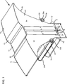
Wie aus
Die Halterung
Die beiden in der Tasche
Aufgrund der Konturgebung des Elements
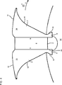
Die
Die Permanentmagneten
Eine Weiterbildung des in
Obschon in der zweiten Ausführungsform in
Die in
Durch den im Vergleich zu
Ein als eine Sammleranordnung konfiguriertes Element aus Halterung und Permanentmagnet kann nicht nachträglich magnetisiert werden, da es nicht möglich ist, die erforderliche magnetische Flussdichte am Magnet aufzubringen.A holder and permanent magnet element configured as a collector assembly can not be subsequently magnetized because it is not possible to apply the required magnetic flux density to the magnet.
Die Montage der Elemente an der Rotornabe wird dergestalt durchgeführt, dass mehrere Elemente entlang eines Schwalbenschwanzes der Rotornabe nacheinander eingeführt werden, so dass ein axiales, vorzugsweise mit Verbindungsmittel kraftschlüssig verbundenes, Elementpaket entsteht. Danach werden die nächsten Elemente um 180 Grad radial versetzt an der Rotornabe angeordnet, bis sie ein komplettes axiales Elementpaket bilden. Je nach Teilung werden die Elemente zunächst so in radialer Reihenfolge angeordnet, dass eine zwischen zwei befüllten Schwalbenschwanzverbindungen bzw. -aufnahmen liegende Schwalbenschwanzaufnahme nicht befüllt wird. Die gerade Anzahl von Elementpaketen wird regelmäßig gegenüberliegend dem Elementpaket mit der vorherigen ungeraden Anzahl angeordnet. Werden nun Elemente zwischen zwei direkt benachbarten Elementen nacheinander eingeführt, stoßen sich die gleichnamigen Polhäften unmittelbar benachbarter Elemente gegeneitig ab. Dadurch wirken auf das einzuführende Element in Umfangsrichtung von beiden Seiten sich gegenseitig aufhebende abstoßende Kräfte, so dass das einzuführende Element sich nicht verkantet. Ferner kann zunächst jeweils eine Führungsplatte an den jeweiligen benachbarten Elementen positioniert werden, so dass sich das einzuführende Element nicht zwischen den zwei benachbarten sowie bereits an der Rotornabe befestigten Elementen verhaken kann.The assembly of the elements on the rotor hub is performed such that a plurality of elements are introduced successively along a dovetail of the rotor hub, so that an axial, preferably non-positively connected with connecting means, element package is formed. Thereafter, the next elements are arranged offset by 180 degrees radially offset on the rotor hub until they form a complete axial element package. Depending on the division, the elements are initially arranged in radial order such that a dovetail receptacle lying between two filled dovetail connections or receptacles is not filled. The even number of element packets is regularly arranged opposite the elementary packet with the previous odd number. If elements between two directly adjacent elements are introduced one after the other, the poles of the same name directly adjacent elements repel each other. As a result, repulsive forces acting on the element to be introduced in the circumferential direction cancel each other out from both sides, so that the element to be introduced does not become jammed. In addition, a guide plate can first be positioned on the respective adjacent elements so that the element to be introduced can not become caught between the two adjacent elements already fastened to the rotor hub.
Die Erfindung lässt neben den erläuterten Ausführungsformen weitere Gestaltungsansätze zu.The invention allows, in addition to the illustrated embodiments, further design approaches.
Obwohl das Element
Obgleich die Zugmittel in der vorliegenden Ausführungsform durch die Rotornabe
Obschon bei den vorliegenden Ausführungsformen eine Schwalbenschwanzverbindung zum Einsatz kommt, sind gleichfalls weitere Nut- und Federverbindung zur Verbindung der Halterung mit der Rotornabe konfigurierbar.Although a dovetail connection is used in the present embodiments, further tongue and groove connections are also configurable to connect the bracket to the rotor hub.
Zwar weist die zweite Ausführungsform der Halterung keine Aufnahme auf, jedoch ist dies ohne Weiteres möglich. So können im Algemeinen die Aufnahmen auch in Seitenflächen der Halterung als Vertiefung eingebracht sein.Although the second embodiment of the holder has no receptacle, but this is readily possible. Thus, in general, the receptacles can also be incorporated in side surfaces of the holder as a depression.
Die Seitenfläche
Obschon in
Obwohl eingangs der vorliegenden Beschreibung eine Synchronmaschine erläutert wurde, kann die Halterung auch bei einer Reihe von elektrischen Maschinen, wie Gleichstrommaschine, usw. verwendet werden. Ferner kann die elektrische Maschine sowohl als Motor als auch als Generator betrieben werden.Although a synchronous machine has been explained at the beginning of the present description, the holder can also be used in a number of electrical machines, such as a DC machine, etc. Furthermore, the electric machine can be operated both as a motor and as a generator.
Zwar ist die Vertiefung
Bezugszeichenliste LIST OF REFERENCE NUMBERS
- 1, 1'1, 1 '
- Elementelement
- 2, 2'2, 2 '
- Halterungbracket
- 44
- Permanentmagnetpermanent magnet
- 6, 6'6, 6 '
- Verbindungsabschnittconnecting portion
- 88th
- Erste StirnflächeFirst face
- 10, 10'10, 10 '
- Schwalbenschwanzverbindungdovetail joint
- 1212
- Zweite StirnflächeSecond face
- 1313
- Verbindungsabschnittconnecting portion
- 1414
- Vertiefungdeepening
- 16, 16'16, 16 '
- Seitenflächeside surface
- 18, 18'18, 18 '
- Seitenflächeside surface
- 2020
- Ösenartige AufnahmeEyelet-like recording
- 20a20a
- Schlitzslot
- 20b20b
- Verbindungsmittelconnecting means
- 2222
- Ösenartige AufnahmeEyelet-like recording
- 22a22a
- Schlitzslot
- 22b22b
- Verbindungsmittelconnecting means
- 24, 24'24, 24 '
- Taschebag
- 2626
- Speichespoke
- 28, 28'28, 28 '
- Erster StegFirst walkway
- 3030
- Zweiter StegSecond pier
- 3232
- SüdpolabschnittSouth Pole section
- 3434
- NordpolabschnittNorth Pole section
- 3636
- Klebstoffadhesive
- 3838
- Spaltgap
- 4040
- Stützelementsupport element
- 4242
- PresseringPress ring
- 4444
- Kühlöffnungcooling vent
- 50, 50'50, 50 '
- Rotornaberotor hub
- 5151
- Manteloberflächecoat surface
- 5252
- Kreisförmige ÖffnungCircular opening
- 5454
- Stirnseite der RotornabeFront side of the rotor hub
- 5656
- Vorsprunghead Start
- 100100
- Rotorrotor
- 102102
- Rotorwellerotor shaft
- 104104
- Lüfterradfan
- 200200
- Statorstator
- 202202
- Statorzahnstator tooth
- RR
- Radialrichtungradial direction
- UU
- Umfangsrichtungcircumferentially
- AA
- Axialrichtungaxially
- ll
- Länge des Permanentmagneten in RadialrichtungLength of the permanent magnet in the radial direction
- bb
- Halbe Breite der HalterungHalf the width of the bracket
- αα
- Winkel zwischen erster Stirnfläche und erster/zweiter SeitenflächeAngle between first end face and first / second side face
ZITATE ENTHALTEN IN DER BESCHREIBUNG QUOTES INCLUDE IN THE DESCRIPTION
Diese Liste der vom Anmelder aufgeführten Dokumente wurde automatisiert erzeugt und ist ausschließlich zur besseren Information des Lesers aufgenommen. Die Liste ist nicht Bestandteil der deutschen Patent- bzw. Gebrauchsmusteranmeldung. Das DPMA übernimmt keinerlei Haftung für etwaige Fehler oder Auslassungen.This list of the documents listed by the applicant has been generated automatically and is included solely for the better information of the reader. The list is not part of the German patent or utility model application. The DPMA assumes no liability for any errors or omissions.
Zitierte PatentliteraturCited patent literature
- EP 1166423 B1 [0002] EP 1166423 B1 [0002]
- DE 102011051947 A1 [0005] DE 102011051947 A1 [0005]
Claims (21)
Priority Applications (7)
| Application Number | Priority Date | Filing Date | Title |
|---|---|---|---|
| DE102012105992A DE102012105992A1 (en) | 2012-07-04 | 2012-07-04 | Element of an electrical machine with a holder and a permanent magnet, component with at least one element and an electric machine |
| KR1020157003031A KR20150067124A (en) | 2012-07-04 | 2013-07-03 | Element of an electrical machine having a holder and a permanent magnet, component having at least one element, and an electrical machine |
| CN201380035693.1A CN104521110A (en) | 2012-07-04 | 2013-07-03 | Element of an electrical machine having a holder and a permanent magnet, component having at least one element, and an electrical machine |
| EP13753267.7A EP2870680A2 (en) | 2012-07-04 | 2013-07-03 | Element of an electrical machine having a holder and a permanent magnet, component having at least one element, and an electrical machine |
| DE201311003380 DE112013003380A5 (en) | 2012-07-04 | 2013-07-03 | Element of an electrical machine with a holder and a permanent magnet, component with at least one element and an electric machine |
| PCT/DE2013/100246 WO2014005580A2 (en) | 2012-07-04 | 2013-07-03 | Element of an electrical machine having a holder and a permanent magnet, component having at least one element, and an electrical machine |
| HK15108761.3A HK1208289A1 (en) | 2012-07-04 | 2015-09-09 | Element of an electrical machine having a holder and a permanent magnet, component having at least one element, and an electrical machine |
Applications Claiming Priority (1)
| Application Number | Priority Date | Filing Date | Title |
|---|---|---|---|
| DE102012105992A DE102012105992A1 (en) | 2012-07-04 | 2012-07-04 | Element of an electrical machine with a holder and a permanent magnet, component with at least one element and an electric machine |
Publications (1)
| Publication Number | Publication Date |
|---|---|
| DE102012105992A1 true DE102012105992A1 (en) | 2013-11-07 |
Family
ID=49036400
Family Applications (2)
| Application Number | Title | Priority Date | Filing Date |
|---|---|---|---|
| DE102012105992A Withdrawn DE102012105992A1 (en) | 2012-07-04 | 2012-07-04 | Element of an electrical machine with a holder and a permanent magnet, component with at least one element and an electric machine |
| DE201311003380 Withdrawn DE112013003380A5 (en) | 2012-07-04 | 2013-07-03 | Element of an electrical machine with a holder and a permanent magnet, component with at least one element and an electric machine |
Family Applications After (1)
| Application Number | Title | Priority Date | Filing Date |
|---|---|---|---|
| DE201311003380 Withdrawn DE112013003380A5 (en) | 2012-07-04 | 2013-07-03 | Element of an electrical machine with a holder and a permanent magnet, component with at least one element and an electric machine |
Country Status (6)
| Country | Link |
|---|---|
| EP (1) | EP2870680A2 (en) |
| KR (1) | KR20150067124A (en) |
| CN (1) | CN104521110A (en) |
| DE (2) | DE102012105992A1 (en) |
| HK (1) | HK1208289A1 (en) |
| WO (1) | WO2014005580A2 (en) |
Cited By (2)
| Publication number | Priority date | Publication date | Assignee | Title |
|---|---|---|---|---|
| EP3276797A1 (en) * | 2016-07-25 | 2018-01-31 | Siemens Aktiengesellschaft | Rotor for an electric rotating machine |
| FR3064837A1 (en) * | 2017-04-03 | 2018-10-05 | Moving Magnet Technologies | ROTOR FOR ELECTRIC MACHINE WITH INTERNAL PERMANENT MAGNETS |
Families Citing this family (3)
| Publication number | Priority date | Publication date | Assignee | Title |
|---|---|---|---|---|
| GB2546298B (en) * | 2016-01-14 | 2022-06-15 | Advanced Electric Machines Group Ltd | Rotor assembly |
| US10211689B2 (en) * | 2016-03-09 | 2019-02-19 | Ford Global Technologies, Llc | Electric machine rotor |
| DE102021116054A1 (en) | 2021-06-22 | 2022-12-22 | Bayerische Motoren Werke Aktiengesellschaft | Process for manufacturing a rotor using a flexible coil carrier, electrical machine and motor vehicle |
Citations (6)
| Publication number | Priority date | Publication date | Assignee | Title |
|---|---|---|---|---|
| DE1994015U (en) * | 1965-06-29 | 1968-09-19 | Lloyd Dynamowerke G M B H | ELECTRIC MACHINE WITH PERMANENT MAGNETIC EXCITER POLES. |
| US4336649A (en) * | 1978-12-26 | 1982-06-29 | The Garrett Corporation | Method of making rotor assembly having anchor with undulating sides |
| DE102007022835A1 (en) * | 2007-05-12 | 2008-11-13 | Esw Gmbh | Rotor for permanent magnet-actuated electrical machine, has blank sheet and insertion plates made of different materials, where one of sheet and plates is magnetizable and other is made of magnetic material |
| US20100127584A1 (en) * | 2007-07-24 | 2010-05-27 | Carlos Gottfried | Clamp and lock permanent magnets within a rotating electrical machine using pitched focused flux magnets |
| EP1166423B1 (en) | 1999-03-19 | 2011-10-26 | Siemens Aktiengesellschaft | Multipole, permanent-magnet rotor for a rotating electrical machine and method for producing such a rotor |
| DE102011051947A1 (en) | 2010-07-28 | 2012-02-02 | General Electric Co. | Segmented rotor |
Family Cites Families (8)
| Publication number | Priority date | Publication date | Assignee | Title |
|---|---|---|---|---|
| DE2659650A1 (en) * | 1976-12-30 | 1978-11-16 | Siemens Ag | Permanent magnet excited motor - incorporates system for intensive magnet cooling to prevent flux reduction due to high temp. |
| FR2655214B1 (en) * | 1989-11-27 | 1992-02-07 | Alsthom Gec | MAGNET MOTOR ROTOR. |
| FR2903824A1 (en) * | 2006-07-13 | 2008-01-18 | Leroy Somer Moteurs | ROTOR OF ELECTRIC ROTATING MACHINE AND METHOD OF MANUFACTURING |
| DE102006043893B4 (en) * | 2006-09-19 | 2008-10-02 | Siemens Ag | Polzahn with permanent magnet |
| DE102009003228B4 (en) * | 2008-06-20 | 2020-11-05 | Robert Bosch Gmbh | Electric machine |
| CN101710775A (en) * | 2009-12-16 | 2010-05-19 | 南京航空航天大学 | Hybrid excitation block type stator and rotor switch reluctance machine |
| DE102010062981A1 (en) * | 2010-12-14 | 2012-06-14 | Robert Bosch Gmbh | Machine component for an electrical machine |
| ES2742265T3 (en) * | 2012-05-02 | 2020-02-13 | Abb Schweiz Ag | An electric machine |
-
2012
- 2012-07-04 DE DE102012105992A patent/DE102012105992A1/en not_active Withdrawn
-
2013
- 2013-07-03 DE DE201311003380 patent/DE112013003380A5/en not_active Withdrawn
- 2013-07-03 KR KR1020157003031A patent/KR20150067124A/en not_active Application Discontinuation
- 2013-07-03 EP EP13753267.7A patent/EP2870680A2/en not_active Withdrawn
- 2013-07-03 WO PCT/DE2013/100246 patent/WO2014005580A2/en active Application Filing
- 2013-07-03 CN CN201380035693.1A patent/CN104521110A/en active Pending
-
2015
- 2015-09-09 HK HK15108761.3A patent/HK1208289A1/en unknown
Patent Citations (6)
| Publication number | Priority date | Publication date | Assignee | Title |
|---|---|---|---|---|
| DE1994015U (en) * | 1965-06-29 | 1968-09-19 | Lloyd Dynamowerke G M B H | ELECTRIC MACHINE WITH PERMANENT MAGNETIC EXCITER POLES. |
| US4336649A (en) * | 1978-12-26 | 1982-06-29 | The Garrett Corporation | Method of making rotor assembly having anchor with undulating sides |
| EP1166423B1 (en) | 1999-03-19 | 2011-10-26 | Siemens Aktiengesellschaft | Multipole, permanent-magnet rotor for a rotating electrical machine and method for producing such a rotor |
| DE102007022835A1 (en) * | 2007-05-12 | 2008-11-13 | Esw Gmbh | Rotor for permanent magnet-actuated electrical machine, has blank sheet and insertion plates made of different materials, where one of sheet and plates is magnetizable and other is made of magnetic material |
| US20100127584A1 (en) * | 2007-07-24 | 2010-05-27 | Carlos Gottfried | Clamp and lock permanent magnets within a rotating electrical machine using pitched focused flux magnets |
| DE102011051947A1 (en) | 2010-07-28 | 2012-02-02 | General Electric Co. | Segmented rotor |
Cited By (5)
| Publication number | Priority date | Publication date | Assignee | Title |
|---|---|---|---|---|
| EP3276797A1 (en) * | 2016-07-25 | 2018-01-31 | Siemens Aktiengesellschaft | Rotor for an electric rotating machine |
| WO2018019487A1 (en) | 2016-07-25 | 2018-02-01 | Siemens Aktiengesellschaft | Rotor for an electric rotating machine |
| FR3064837A1 (en) * | 2017-04-03 | 2018-10-05 | Moving Magnet Technologies | ROTOR FOR ELECTRIC MACHINE WITH INTERNAL PERMANENT MAGNETS |
| WO2018185421A1 (en) * | 2017-04-03 | 2018-10-11 | Moving Magnet Technologies | Rotor for electrical machine having internal permanent magnets |
| US11362555B2 (en) | 2017-04-03 | 2022-06-14 | Moving Magnet Technologies | Rotor with permanent magnets forming a portion of a rotor core |
Also Published As
| Publication number | Publication date |
|---|---|
| WO2014005580A2 (en) | 2014-01-09 |
| WO2014005580A3 (en) | 2014-07-17 |
| EP2870680A2 (en) | 2015-05-13 |
| KR20150067124A (en) | 2015-06-17 |
| DE112013003380A5 (en) | 2015-04-23 |
| HK1208289A1 (en) | 2016-02-26 |
| CN104521110A (en) | 2015-04-15 |
Similar Documents
| Publication | Publication Date | Title |
|---|---|---|
| EP0729217B1 (en) | Hybride excited synchronous machine | |
| DE112010003859B4 (en) | Lundell-type rotary motor | |
| EP1711994B1 (en) | Stator module | |
| EP2766976B1 (en) | Optimized spider rotor internal geometry | |
| EP0729216A2 (en) | Hybride excited synchronous machine | |
| DE112014000526T5 (en) | Rotor and rotating electrical machine containing this rotor | |
| DE10215251A1 (en) | Electrical machine, in particular permanent magnet excited motors | |
| DE102006000455A1 (en) | Internal permanent magnet rotor and internal permanent magnet motor | |
| DE102012105992A1 (en) | Element of an electrical machine with a holder and a permanent magnet, component with at least one element and an electric machine | |
| WO2016020120A2 (en) | Sheet metal part or sintered part for a stator or a rotor of an electrical machine and method for producing same | |
| DE102007056116B4 (en) | Permanent-magnet electric machine | |
| DE102019206460B3 (en) | Rotating multiphase transverse flux machine | |
| DE10229333A1 (en) | Electrical machine, especially brushless machine with permanent magnet stimulated rotor, has teeth with separating layer(s) of increased magnetic resistance perpendicular to transverse magnetic field | |
| WO2017198406A1 (en) | Rotor of an electric machine with a laminated core | |
| DE112019007070T5 (en) | ROTATING ELECTRIC MACHINE | |
| DE102007032135A1 (en) | Electric machine | |
| DE102010036828A1 (en) | Annular stator for electro-dynamic machine, has U-shaped core metal sheets that are provided with two parallel legs for guiding magnetic flux within each coil | |
| WO2019154573A1 (en) | Permanently excited synchronous machine having reduced pendulum torque | |
| EP2507894B1 (en) | Electric machine excited by permanent magnets | |
| DE10247907A1 (en) | Rotor for electrical machine e.g. synchronous machine, has corresponding guide elements at permanent magnets and carrier engaging into each other for secure hold | |
| EP3014749B1 (en) | Electrical machine | |
| EP3579383B1 (en) | Torque-optimised multipolar rotor for an electric motor | |
| DE102020101849A1 (en) | A rotor for an axial flux machine, a method for producing a rotor for an axial flux machine and an axial flux machine | |
| DE102021102202A1 (en) | Laminated core with form-fit body for power transmission | |
| WO2020177984A1 (en) | Laminated core for an electric machine |
Legal Events
| Date | Code | Title | Description |
|---|---|---|---|
| R163 | Identified publications notified | ||
| R082 | Change of representative |
Representative=s name: ZACCO DR. PETERS UND PARTNER, DE |
|
| R118 | Application deemed withdrawn due to claim for domestic priority | ||
| R118 | Application deemed withdrawn due to claim for domestic priority |
Effective date: 20150105 |
|
| R082 | Change of representative |