DE102012104767A1 - Conical honeycomb body with obliquely radial channels - Google Patents
Conical honeycomb body with obliquely radial channels Download PDFInfo
- Publication number
- DE102012104767A1 DE102012104767A1 DE102012104767A DE102012104767A DE102012104767A1 DE 102012104767 A1 DE102012104767 A1 DE 102012104767A1 DE 102012104767 A DE102012104767 A DE 102012104767A DE 102012104767 A DE102012104767 A DE 102012104767A DE 102012104767 A1 DE102012104767 A1 DE 102012104767A1
- Authority
- DE
- Germany
- Prior art keywords
- honeycomb body
- layers
- sheet metal
- intermediate layer
- structured
- Prior art date
- Legal status (The legal status is an assumption and is not a legal conclusion. Google has not performed a legal analysis and makes no representation as to the accuracy of the status listed.)
- Withdrawn
Links
Images


Classifications
-
- F—MECHANICAL ENGINEERING; LIGHTING; HEATING; WEAPONS; BLASTING
- F01—MACHINES OR ENGINES IN GENERAL; ENGINE PLANTS IN GENERAL; STEAM ENGINES
- F01N—GAS-FLOW SILENCERS OR EXHAUST APPARATUS FOR MACHINES OR ENGINES IN GENERAL; GAS-FLOW SILENCERS OR EXHAUST APPARATUS FOR INTERNAL COMBUSTION ENGINES
- F01N3/00—Exhaust or silencing apparatus having means for purifying, rendering innocuous, or otherwise treating exhaust
- F01N3/08—Exhaust or silencing apparatus having means for purifying, rendering innocuous, or otherwise treating exhaust for rendering innocuous
- F01N3/10—Exhaust or silencing apparatus having means for purifying, rendering innocuous, or otherwise treating exhaust for rendering innocuous by thermal or catalytic conversion of noxious components of exhaust
- F01N3/24—Exhaust or silencing apparatus having means for purifying, rendering innocuous, or otherwise treating exhaust for rendering innocuous by thermal or catalytic conversion of noxious components of exhaust characterised by constructional aspects of converting apparatus
- F01N3/28—Construction of catalytic reactors
- F01N3/2803—Construction of catalytic reactors characterised by structure, by material or by manufacturing of catalyst support
- F01N3/2807—Metal other than sintered metal
- F01N3/281—Metallic honeycomb monoliths made of stacked or rolled sheets, foils or plates
- F01N3/2814—Metallic honeycomb monoliths made of stacked or rolled sheets, foils or plates all sheets, plates or foils being corrugated
-
- F—MECHANICAL ENGINEERING; LIGHTING; HEATING; WEAPONS; BLASTING
- F01—MACHINES OR ENGINES IN GENERAL; ENGINE PLANTS IN GENERAL; STEAM ENGINES
- F01N—GAS-FLOW SILENCERS OR EXHAUST APPARATUS FOR MACHINES OR ENGINES IN GENERAL; GAS-FLOW SILENCERS OR EXHAUST APPARATUS FOR INTERNAL COMBUSTION ENGINES
- F01N2230/00—Combination of silencers and other devices
- F01N2230/02—Exhaust filters
-
- F—MECHANICAL ENGINEERING; LIGHTING; HEATING; WEAPONS; BLASTING
- F01—MACHINES OR ENGINES IN GENERAL; ENGINE PLANTS IN GENERAL; STEAM ENGINES
- F01N—GAS-FLOW SILENCERS OR EXHAUST APPARATUS FOR MACHINES OR ENGINES IN GENERAL; GAS-FLOW SILENCERS OR EXHAUST APPARATUS FOR INTERNAL COMBUSTION ENGINES
- F01N2230/00—Combination of silencers and other devices
- F01N2230/04—Catalytic converters
-
- F—MECHANICAL ENGINEERING; LIGHTING; HEATING; WEAPONS; BLASTING
- F01—MACHINES OR ENGINES IN GENERAL; ENGINE PLANTS IN GENERAL; STEAM ENGINES
- F01N—GAS-FLOW SILENCERS OR EXHAUST APPARATUS FOR MACHINES OR ENGINES IN GENERAL; GAS-FLOW SILENCERS OR EXHAUST APPARATUS FOR INTERNAL COMBUSTION ENGINES
- F01N2330/00—Structure of catalyst support or particle filter
- F01N2330/02—Metallic plates or honeycombs, e.g. superposed or rolled-up corrugated or otherwise deformed sheet metal
- F01N2330/04—Methods of manufacturing
-
- F—MECHANICAL ENGINEERING; LIGHTING; HEATING; WEAPONS; BLASTING
- F01—MACHINES OR ENGINES IN GENERAL; ENGINE PLANTS IN GENERAL; STEAM ENGINES
- F01N—GAS-FLOW SILENCERS OR EXHAUST APPARATUS FOR MACHINES OR ENGINES IN GENERAL; GAS-FLOW SILENCERS OR EXHAUST APPARATUS FOR INTERNAL COMBUSTION ENGINES
- F01N2330/00—Structure of catalyst support or particle filter
- F01N2330/30—Honeycomb supports characterised by their structural details
- F01N2330/32—Honeycomb supports characterised by their structural details characterised by the shape, form or number of corrugations of plates, sheets or foils
- F01N2330/321—Honeycomb supports characterised by their structural details characterised by the shape, form or number of corrugations of plates, sheets or foils with two or more different kinds of corrugations in the same substrate
-
- F—MECHANICAL ENGINEERING; LIGHTING; HEATING; WEAPONS; BLASTING
- F01—MACHINES OR ENGINES IN GENERAL; ENGINE PLANTS IN GENERAL; STEAM ENGINES
- F01N—GAS-FLOW SILENCERS OR EXHAUST APPARATUS FOR MACHINES OR ENGINES IN GENERAL; GAS-FLOW SILENCERS OR EXHAUST APPARATUS FOR INTERNAL COMBUSTION ENGINES
- F01N2330/00—Structure of catalyst support or particle filter
- F01N2330/30—Honeycomb supports characterised by their structural details
- F01N2330/32—Honeycomb supports characterised by their structural details characterised by the shape, form or number of corrugations of plates, sheets or foils
- F01N2330/324—Corrugations of rectangular form
-
- Y—GENERAL TAGGING OF NEW TECHNOLOGICAL DEVELOPMENTS; GENERAL TAGGING OF CROSS-SECTIONAL TECHNOLOGIES SPANNING OVER SEVERAL SECTIONS OF THE IPC; TECHNICAL SUBJECTS COVERED BY FORMER USPC CROSS-REFERENCE ART COLLECTIONS [XRACs] AND DIGESTS
- Y10—TECHNICAL SUBJECTS COVERED BY FORMER USPC
- Y10T—TECHNICAL SUBJECTS COVERED BY FORMER US CLASSIFICATION
- Y10T428/00—Stock material or miscellaneous articles
- Y10T428/12—All metal or with adjacent metals
- Y10T428/1234—Honeycomb, or with grain orientation or elongated elements in defined angular relationship in respective components [e.g., parallel, inter- secting, etc.]
Abstract
Die vorliegende Erfindung betrifft einen aus Lagen (2, 3) gewickelten und/oder geschichteten Wabenkörper (1) mit einer geometrischen Mittelachse (4) und einem um die Mittelachse (4) herum rotationssymmetrisch angeordneten Hohlraum (5), sowie einer äußeren Mantelfläche (6), wobei jede Lage (2, 3) annähernd konzentrisch um die Mittelachse (4) verläuft, wobei mindestens eine der Lagen (2) zumindest teilweise strukturiert ist, so dass die Lagen (2, 3) eine Vielzahl von für ein Fluid durchströmbaren Kanälen (7) bilden, die von dem Hohlraum (5) in einem nicht rechten Konuswinkel (α) zur Mittelachse (4) nach außen zur äußeren Mantelfläche (6) verlaufen, und wobei die Kanäle (7) einen sich in ihrem Verlauf von innen nach außen ändernden Kanalquerschnitt (7i, 7a) aufweisen. Bevorzugt beträgt der Konuswinkel (α) zur Mittelachse (4) 25° bis 85°, vorzugsweise 40° bis 70°, insbesondere etwa 45°. Die besondere Form entsteht insbesondere dadurch, dass mindestens eine strukturierte Lage (2) im Wechsel mit mindestens einer Zwischenlage (3; 8; 13; 23; 33) angeordnet ist, wobei beide Lagen wendelförmig aufeinander geschichtet sind und wobei die die Kanäle (7) bildende Strukturhöhe (H) der strukturierten Blechlage (2) im Wesentlichen konstant ist und die Kanalquerschnittsflächen (7i, 7a) von innen nach außen zunehmen. Die Zwischenlage (3) kann aus einfachen Drähten (8) oder aus speziell geschnittenen oder gefalteten glatten Blechen (13; 23; 33) gebildet sein.The present invention relates to a honeycomb body (1) wound and / or layered from layers (2, 3) with a geometric central axis (4) and a cavity (5) rotationally symmetrical about the central axis (4) and an outer lateral surface (6) ), wherein each layer (2, 3) extends approximately concentrically about the central axis (4), wherein at least one of the layers (2) is at least partially structured, so that the layers (2, 3) a plurality of channels through which a fluid can flow (7) extending from the cavity (5) at a non-right cone angle (α) to the central axis (4) outwardly to the outer surface (6), and wherein the channels (7) in their course from the inside to have outside changing channel cross-section (7i, 7a). Preferably, the cone angle (α) to the central axis (4) is 25 ° to 85 °, preferably 40 ° to 70 °, in particular about 45 °. The particular shape arises in particular in that at least one structured layer (2) is arranged in alternation with at least one intermediate layer (3; 8; 13; 23; 33), wherein both layers are helically stacked on one another and wherein the channels (7) forming structural height (H) of the structured sheet metal layer (2) is substantially constant and increase the channel cross-sectional areas (7i, 7a) from the inside to the outside. The intermediate layer (3) can be formed from simple wires (8) or from specially cut or folded smooth sheets (13; 23; 33).
Description
Die vorliegende Erfindung betrifft einen aus Lagen gewickelten und/oder geschichteten Wabenkörper, wie er insbesondere bei der Gasreinigung eingesetzt wird. Bei Abgasreinigungsanlagen, insbesondere für Verbrennungsmotoren von Kraftfahrzeugen, werden mit katalytisch aktivem Material beschichtete und/oder zur Abscheidung von Partikeln besonders ausgebildete Wabenkörper eingesetzt, wobei oft metallische Materialien für die Wabenkörper eingesetzt werden. The present invention relates to a wound from layers and / or layered honeycomb body, as used in particular in gas purification. In exhaust gas purification systems, in particular for internal combustion engines of motor vehicles, honeycomb bodies coated with catalytically active material and / or specially designed for the separation of particles are used, metallic materials often being used for the honeycomb bodies.
Gerade bei Anwendungen für Kraftfahrzeuge müssen unterschiedliche Rahmenbedingungen beachtet werden. Zum einen ist der vorhandene Platz für den Einbau von Abgasreinigungssystemen beschränkt, zum anderen sollen die Systeme keinen großen Druckverlust im Abgassystem erzeugen, da dies den Wirkungsgrad von Verbrennungsmotoren negativ beeinflusst. Especially in applications for motor vehicles different conditions must be considered. On the one hand, the space available for the installation of emission control systems is limited, on the other hand, the systems should not produce a large pressure drop in the exhaust system, as this adversely affects the efficiency of internal combustion engines.
Im Stand der Technik sind bereits zahlreiche Bauformen für gewickelte oder geschichtete Wabenkörper bekannt, darunter Bauformen mit axial in einer Strömungsrichtung verlaufenden Kanälen, Bauformen mit radial von einem inneren Hohlraum nach außen zu einem Sammelraum verlaufenden Kanälen und auch konische Wabenkörper, bei denen von einer Stirnseite zu einer gegenüberliegenden Stirnseite sich im Querschnitt erweiternde Kanäle verlaufen. Numerous designs for wound or layered honeycomb bodies are already known in the prior art, including designs with channels running axially in a flow direction, designs with channels running radially from an inner cavity to the outside to a collection chamber, and also conical honeycomb bodies in which from one end face to an opposite end face extend in cross-section widening channels.
Viele unterschiedliche Bauformen sind auch in der
Aufgabe der vorliegenden Erfindung ist es, einen Wabenkörper der genannten Art so weiterzuentwickeln, dass er leicht, insbesondere in einer Serienproduktion, herstellbar ist und an unterschiedliche Platzverhältnisse beim Einbau anpassbar ist. Auch soll er Bauformen ermöglichen, die relativ große Oberflächen zur Abgasreinigung bei relativ geringem Druckverlust zur Verfügung stellen.Object of the present invention is to develop a honeycomb body of the type mentioned so that it is easy, especially in a mass production, can be produced and adapted to different space conditions during installation. He should also allow designs that provide relatively large surfaces for emission control at relatively low pressure loss available.
Zur Lösung dieser Aufgabe dient ein Wabenkörper gemäß dem Anspruch 1. Vorteilhafte Ausgestaltungen, die einzeln oder technisch sinnvoll untereinander kombiniert einsetzbar sind, sind in den abhängigen Ansprüchen beschrieben. To achieve this object is a honeycomb body according to
Ein erfindungsgemäßer aus Lagen gewickelter und/oder geschichteter Wabenkörper hat eine geometrische Mittelachse und einen um die Mittelachse herum rotationssymmetrisch angeordneten Hohlraum sowie eine äußere Mantelfläche, wobei jede Lage annähernd konzentrisch um die Mittelachse verläuft, wobei mindestens eine der Lagen zumindest teilweise strukturiert ist, so dass die Lagen eine Vielzahl von für ein Fluid durchströmbaren Kanälen bilden, die von dem Hohlraum in einem nicht rechten Konuswinkel zur Mittelachse nach außen zur äußeren Mantelfläche verlaufen, und wobei die Kanäle einen sich in ihrem Verlauf von innen nach außen ändernden Kanalquerschnitt aufweisen.An inventive layered and / or layered honeycomb body has a geometric central axis and a rotationally symmetrical cavity about the central axis and an outer lateral surface, each layer approximately concentric about the central axis, wherein at least one of the layers is at least partially textured such that the layers form a plurality of fluid-flow channels extending from the cavity at a non-right cone angle to the central axis out to the outer surface, and wherein the channels have a changing in their course from the inside to the outside channel cross-section.
Erfindungsgemäß laufen die Kanäle nicht genau radial von innen nach außen, also nicht senkrecht zur Mittelachse, sondern in einem Winkel dazu. Dies verringert den Druckverlust gegenüber genau radial verlaufenden Kanälen, weil die zweimalige Umlenkung des Fluids weniger stark ist. Die einzelnen Lagen haben bei dieser Bauform etwa die Form eines Trichters, wobei insbesondere eine Bauweise in Wendelform in Betracht kommt, so dass die Lagen nicht in sich geschlossen sind, sondern ähnlich einer Wendeltreppe, allerdings mit einem nicht rechten Winkel zur Mittelachse, verlaufen. Diese erfindungsgemäße Bauform bietet vor allem in Kombination mit anderen Bauformen eine zusätzliche Flexibilität bei der Ausnutzung von vorhandenem Bauraum und bei der Verringerung von Druckverlusten.According to the invention, the channels do not run exactly radially from the inside to the outside, that is not perpendicular to the central axis, but at an angle thereto. This reduces the pressure loss compared to exactly radially extending channels, because the two-time deflection of the fluid is less strong. The individual layers have in this design, about the shape of a funnel, in particular a construction in helical form is considered, so that the layers are not self-contained, but similar to a spiral staircase, but with a non-right angle to the central axis run. This design according to the invention, especially in combination with other designs, offers additional flexibility in the utilization of available installation space and in the reduction of pressure losses.
In einem bevorzugten Ausführungsbeispiel der Erfindung sind der Hohlraum und/oder die Mantelfläche zylindrisch ausgestaltet. Schon aus fertigungstechnischen Gründen ist diese Bauform bevorzugt, da alle strukturierten Lagen die gleiche Form aufweisen können. In a preferred embodiment of the invention, the cavity and / or the lateral surface are cylindrical. Even for manufacturing reasons, this design is preferred because all structured layers may have the same shape.
Weiterhin wird erfindungsgemäß ein Konuswinkel zur Mittelachse von 25° bis 85° vorgeschlagen, bevorzugt 40° bis 70°, wobei für viele Anwendungen ein Winkel von etwa 45° besonders geeignet ist.Furthermore, a cone angle to the central axis of 25 ° to 85 ° is proposed according to the invention, preferably 40 ° to 70 °, with an angle of about 45 ° is particularly suitable for many applications.
Um reine relativ einfache Fertigung zu ermöglichen, sieht eine Ausführungsform der Erfindung vor, dass mindestens eine strukturierte Lage im Wechsel mit mindestens einer Zwischenlage angeordnet ist, wobei beide Lagen wendelförmig aufeinander geschichtet sind. Die Zwischenlage dient im Wesentlichen dazu, den Abstand zwischen den strukturierten Lagen aufrecht zu erhalten, so dass diese nicht mit ihren Strukturen ineinander rutschen können.In order to enable a relatively simple production, an embodiment of the invention provides that at least one structured layer is arranged in alternation with at least one intermediate layer, wherein both layers are helically stacked on top of each other. The intermediate layer essentially serves to maintain the distance between the structured layers so that they can not slip into one another with their structures.
Eine wesentliche Problematik bei der Herstellung erfindungsgemäßer Wabenkörper besteht darin, die einzelnen Lagen so auszugestalten, dass sie in die gewünschte Wendelform gebracht werden können und die gewünschten Struktureigenschaften haben. Da für solche Wabenkörper typischerweise verwendete Bleche als lange gerade Streifen, aufgewickelt in sogenannten Coils, geliefert werden, ist eine geeignete Umformung erforderlich, wobei diese die durch den Werkstoff gegebenen Grenzen nicht überschreiten darf. In einer Ausführungsform der Erfindung werden die strukturierten Lagen so geformt, dass die die Kanäle bildende Strukturhöhe der strukturierten Blechlage im Wesentlichen konstant ist und die Kanalquerschnittsflächen von innen nach außen zunehmen. An essential problem in the production of honeycomb bodies according to the invention consists in designing the individual layers in such a way that they can be brought into the desired spiral shape and have the desired structural properties. Since sheets typically used for such honeycomb bodies are supplied as long straight strips wound up in so-called coils, suitable forming is required, and this must not exceed the limits given by the material. In one embodiment of the invention, the structured layers are shaped the structural height of the structured sheet-metal layer forming the channels is substantially constant and the channel cross-sectional areas increase from the inside to the outside.
Durch die konstante Strukturhöhe bleibt der Verlauf aufeinanderfolgender Lagen in dem Wabenkörper in etwa parallel, was bspw. bei konischen Wabenkörpern mit von einer Stirnseite zur anderen verlaufenden Kanälen zunehmender Querschnittsflächen nicht der Fall ist. Due to the constant height of the structure, the course of successive layers in the honeycomb body remains approximately parallel, which is not the case, for example, with conical honeycomb bodies having channels of increasing cross-sectional area extending from one end face to the other.
Die konstante Strukturhöhe lässt sich in einem Ausführungsbeispiel der Erfindung insbesondere dadurch erreichen, dass die strukturierte Blechlage eine Struktur aufweist, die im Zusammenwirken mit angrenzenden Zwischenlagen Kanäle bildet, deren Berandung durch eine Flankenwellung der strukturierten Blechlage überall im Wesentlichen die gleiche Länge hat, aber deren Kanalquerschnittsfläche bei etwa konstanter Strukturhöhe von innen nach außen zunimmt. Dies bedeutet, dass die Flankenwellung innen eine ziemlich starke Krümmung aufweist, also in sehr engen Wellungen verläuft, während sie im äußeren Bereich immer weiter auseinandergezogen wird, so dass die zugehörige Kanalquerschnittsfläche immer größer wird. Solche Wellformen lassen sich mit bekannten Maschinen zur Wellung von Blechlagen und ein anschließendes Auseinanderziehen einer Seite bzw. ein anschließendes Zusammenstauchen der anderen Seite herstellen. In one exemplary embodiment of the invention, the constant height of the structure can be achieved, in particular, by the structured sheet-metal layer forming channels in cooperation with adjacent intermediate layers, the boundary of which has essentially the same length throughout a flared curvature of the structured sheet-metal layer, but its channel cross-sectional area increases at an approximately constant structural height from inside to outside. This means that the flared curvature has a rather large curvature on the inside, that is to say runs in very narrow corrugations, while it is pulled apart further and further in the outer region, so that the associated channel cross-sectional area becomes ever larger. Such corrugations can be produced with known machines for corrugating sheet metal layers and then pulling apart one side or a subsequent upsetting of the other side.
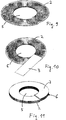
Sofern man für den gesamten Wabenkörper gleichartige Lagen einsetzt, entsteht erfindungsgemäß eine Form, bei der der Hohlraum gegenüber der Mantelfläche axial versetzt angeordnet ist, so dass der Wabenkörper eine erste konische und eine zweite hohlkonische Stirnseite aufweist. Diese Form ist strömungstechnisch günstig nutzbar und erlaubt insbesondere die Kombination mit anderen Wabenkörpern zur Ausnutzung vorhandener Freiräume.If identical layers are used for the entire honeycomb body, according to the invention a shape is produced in which the hollow space is offset axially relative to the lateral surface, so that the honeycomb body has a first conical and a second hollow conical face. This form is aerodynamically useful and allows in particular the combination with other honeycomb bodies for the use of existing open spaces.
Da die Herstellung von wendelförmig verlaufenden kontinuierlichen glatten Blechlagen eine sehr starke Verformung erfordern würde, wird bei einem Ausführungsbeispiel der Erfindung vorgeschlagen, alle Lagen strukturiert zu gestalten, und zwar abwechselnd strukturierte Blechlagen mit einer groben Struktur und Zwischenlagen mit einer feinen Struktur, wobei die Dimensionen von grober und feiner Struktur sich um mindestens einen Faktor 3, vorzugsweise um einen Faktor 5 bis 10, unterscheiden. Durch die Verwendung unterschiedlicher Dimensionen bei der Struktur wird erreicht, dass sich durch die grobe Struktur im Wesentlichen die Form der Kanäle ergibt, während die feine Struktur der Zwischenlagen ein Ineinanderrutschen der groben Strukturen verhindert. Auf diese Weise lassen sich daher zwei wendelförmig geformte unterschiedliche strukturierte Lagen zu einem sehr gleichmäßigen Wabenkörper aufeinanderschichten. Since the production of helically running continuous smooth sheet metal layers would require a very large deformation, it is proposed in one embodiment of the invention to make all layers structured, namely alternately structured sheet metal layers with a coarse structure and intermediate layers with a fine structure, the dimensions of coarse and fine structure differ by at least a factor of 3, preferably by a factor of 5 to 10. By using different dimensions in the structure, it is achieved that the rough structure essentially results in the shape of the channels, while the fine structure of the intermediate layers prevents the coarse structures from slipping into one another. In this way, therefore, two helically shaped different structured layers can be stacked to form a very uniform honeycomb body.
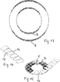
Eine alternative Ausführungsform ist die Verwendung von Zwischenlagen mit Schlitzen, die vorzugsweise von der äußeren Mantelfläche nach innen verlaufen und außen aufgespreitzt sind. Auf diese Weise entsteht eine innen zusammenhängende Zwischenlage, die das Ineinanderrutschen der strukturierten Blechlagen verhindern kann, auch wenn die Schlitze nach außen immer weiter geöffnet sind. An alternative embodiment is the use of intermediate layers with slots, which preferably extend inwards from the outer lateral surface and are externally split. In this way, an internally continuous intermediate layer, which can prevent the slipping of the structured sheet-metal layers, even if the slots are opened to the outside more and more.
Alternativ, allerdings mit dem Verlust von Material bei der Produktion verbunden, ist eine Ausgestaltung der Erfindung, bei der die Zwischenlage mit dreieckigen Ausschnitten versehen ist, die so bemessen sind, dass die Zwischenlage nach Biegen in ihre wendelförmige Endform wieder eine annähernd geschlossene Zwischenlage bildet. Auf diese Weise lässt sich ohne starke Verformung die gewünschte wendelförmige Form der Zwischenlage erreichen und außerdem ein Ineinanderrutschen der strukturierten benachbarten Blechlagen sicher vermeiden. Alternatively, however, associated with the loss of material in the production, is an embodiment of the invention in which the intermediate layer is provided with triangular cut-outs, which are dimensioned so that the intermediate layer again forms an approximately closed intermediate layer after bending into its helical end shape. In this way, can achieve the desired helical shape of the intermediate layer without strong deformation and also safely avoid slippage of the structured adjacent sheet metal layers.
Eine weitere fertigungstechnische Alternative besteht erfindungsgemäß darin, die Zwischenlage entlang von Faltlinien so zu falten, dass sich Überlappungen mit dreifacher Materialstärke bilden und ein annähernd wendelförmiger Verlauf der Zwischenlage entsteht. Hierbei sind keine Schneidwerkzeuge erforderlich und es entsteht auch kein Abfall, allerdings kann ein Teil der Flächen durch die Überlappungen nicht mehr für einen Kontakt mit einem hindurchströmenden Fluid genutzt werden. Trotzdem ist diese Bauform für eine kontinuierliche Produktion sehr hilfreich und die entstehenden Überlappungen stellen bei den typischerweise verwendeten dünnen Blechen kein produktionstechnisches Problem dar. Another manufacturing alternative according to the invention consists in folding the intermediate layer along fold lines so that overlaps with a triple material thickness are formed and an approximately helical course of the intermediate layer is formed. In this case no cutting tools are required and there is no waste, however, a part of the surfaces can not be used by the overlaps for contact with a fluid flowing through. Nevertheless, this design is very helpful for continuous production and the resulting overlaps do not represent a technical production problem with the typically used thin sheets.
Bei einer anderen Ausführungsform der Erfindung werden als Zwischenlage ein Draht oder mehrere Drähte eingelegt, die wendelförmig zwischen den strukturierten Blechlagen verlaufen, vorzugsweise in in den strukturierten Blechlagen vorgefertigten Einlegenuten. Die Einlegenuten können bei der Formgebung der strukturierten Blechlagen direkt mit erzeugt werden und es genügen im Allgemeinen schon zwei mit Abstand zueinander verlaufende Drähte, um ein Ineinanderrutschen der strukturierten Blechlagen sicher zu vermeiden. Je nach Art der Strukturen kann sogar schon ein Draht ausreichen, bei großen Wabenkörpern sind drei oder mehr Drähte vorteilhaft. In another embodiment of the invention, a wire or a plurality of wires are inserted as an intermediate layer, which run helically between the structured sheet metal layers, preferably in pre-fabricated in the structured sheet metal layers insertion grooves. The insertion grooves can be generated directly with the shaping of the structured sheet-metal layers and it is generally sufficient to have two wires running at a distance from one another in order to reliably prevent the structured sheet-metal layers from slipping into one another. Depending on the nature of the structures, even one wire may suffice; in the case of large honeycomb bodies, three or more wires are advantageous.
Erfindungsgemäß kommen für die strukturierten Blechlagen, bevorzugt für alle in dem Wabenkörper verwendeten Lagen, hochtemperaturkorrosionsbeständige Materialien in Betracht, insbesondere Stähle, die Chrom und/oder Aluminium und/oder Nickel enthalten. Für hohe Temperaturen, insbesondere in Abgasanlagen von Kraftfahrzeugen haben sich solche Materialien bewährt. Sie lassen sich außerdem durch erprobte Löttechniken untereinander verbinden, insbesondere durch Hochtemperaturvakuumlöten. Diese Verbindungstechnik kommt insbesondere auch für die erfindungsgemäßen Wabenkörper an den Berührungsstellen der Lagen zur Anwendung, um den Körper zu stabilisieren.According to the invention, high-temperature corrosion-resistant materials are suitable for the structured sheet-metal layers, preferably for all layers used in the honeycomb body, in particular steels which contain chromium and / or aluminum and / or nickel. For high temperatures, especially in exhaust systems of motor vehicles have such materials prove themselves. They can also be interconnected by proven soldering techniques, especially by high temperature vacuum soldering. This connection technique is used in particular for the honeycomb body according to the invention at the contact points of the layers in order to stabilize the body.
Bei Wabenkörpern, die für die Abscheidung von Teilchen, insbesondere Rußpartikeln, eingesetzt werden, ist es vorteilhaft, zumindest einen Teil der Lagen aus porösem Material vorzusehen, vorzugsweise aus einem porösen metallischen Material, insbesondere aus Metallfasermaterial und/oder Sintermaterial. Solche Materialien verbessern die Abscheidung von Rußpartikeln und erlauben eine Strömungsführung, bei denen zumindest ein Teil der Strömung innerhalb des porösen Materials verläuft. In honeycomb bodies, which are used for the deposition of particles, in particular soot particles, it is advantageous to provide at least a portion of the layers of porous material, preferably of a porous metallic material, in particular of metal fiber material and / or sintered material. Such materials improve the deposition of soot particles and allow flow guidance in which at least a portion of the flow is within the porous material.
Die beschriebenen Wabenkörper werden erfindungsgemäß bevorzugt als Katalysatorträgerkörper eingesetzt, also mit einer katalytisch aktiven Beschichtung versehen, die die Umsetzung von Schadstoffen in einem Abgas fördert.According to the invention, the honeycomb bodies described are preferably used as catalyst carrier bodies, that is to say provided with a catalytically active coating which promotes the conversion of pollutants into an exhaust gas.
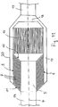
Die erfindungsgemäße Bauform eines Wabenkörpers erfordert es nicht, dass der Hohlraum an einem Ende geschlossen ist, so dass alles dem Hohlraum zugeführte Abgas durch den Wabenkörper schräg nach außen strömt. Es ist möglich, den Hohlraum an beiden Seiten offen zu gestalten und einen weiteren Wabenkörper, insbesondere einen zylindrischen, axial durchströmbaren Wabenkörper kombiniert mit dem erfindungsgemäßen Wabenkörper anzuordnen, insbesondere in einem gemeinsamen Gehäuse und mit fluchtenden geometrischen Mittelachsen. Auf diese Weise kann ein vorhandener Bauraum besonders gut ausgenutzt werden und es entstehen geringere Druckverluste als bei herkömmlichen Anordnungen. The inventive design of a honeycomb body does not require that the cavity is closed at one end, so that all the exhaust gas supplied to the cavity flows obliquely through the honeycomb body to the outside. It is possible to make the cavity open on both sides and to arrange a further honeycomb body, in particular a cylindrical, axially permeable honeycomb body combined with the honeycomb body according to the invention, in particular in a common housing and with aligned geometric central axes. In this way, an existing space can be used particularly well and there are lower pressure drops than in conventional arrangements.
Bei einer bevorzugten Anwendung der Erfindung ist der beschriebene Wabenkörper Teil eines Abgasbehandlungssystems, vorzugsweise eines Verbrennungsmotors, insbesondere eines Kraftfahrzeugs. In a preferred application of the invention, the described honeycomb body is part of an exhaust gas treatment system, preferably an internal combustion engine, in particular of a motor vehicle.
Ausführungsbeispiele und das Umfeld der Erfindung werden im Folgenden anhand der Zeichnung näher beschrieben. Die Erfindung ist nicht auf diese Ausführungsbeispiele beschränkt, jedoch können anhand verschiedener Figuren beschriebene Merkmale in sinnvoller Weise miteinander kombiniert werden. Es sei darauf hingewiesen, dass ein Teil der anhand der Zeichnungen beschriebenen Bauformen und Herstellungsverfahren sich auch für die Serienproduktion von Wabenkörpern mit exakt radial nach außen verlaufenden Kanälen eignet, also mit Kanälen, die senkrecht zu einer geometrischen Mittelachse nach außen verlaufen. Ein Teil der Figuren zeigt zur Veranschaulichung solche Bauformen, obwohl sich die vorliegende Erfindung auf schräg verlaufende Kanäle und im Wesentlichen trichterförmige Lagen bezieht. Die gezeigten Darstellungen enthalten aber ebenso wichtige Konzepte für die Herstellung von exakt radialen Kanälen in Wabenkörpern, die Gegenstand anderer Erfindungen sind. Es zeigen:Embodiments and the environment of the invention will be described in more detail below with reference to the drawing. The invention is not limited to these embodiments, however, features described with reference to various figures can be combined in a meaningful manner. It should be noted that a part of the designs and manufacturing methods described with reference to the drawings is also suitable for the series production of honeycomb bodies with exactly radially outwardly extending channels, that is, with channels that run outward perpendicular to a geometrical central axis. Some of the figures are illustrative of such designs, although the present invention relates to sloped channels and generally funnel-shaped layers. However, the illustrations shown also contain important concepts for the production of exactly radial channels in honeycomb bodies, which are the subject of other inventions. Show it:
Die
In den folgenden Figuren sind der Einfachheit halber keine trichterförmigen, konischen Lagen dargestellt, sondern flache Strukturen, an denen sich die Einzelheiten der Erfindung leichter veranschaulichen lassen. Entsprechend der vorliegenden Erfindung sollen diese Lagen jedoch zusätzlich zu den dargestellten und beschriebenen Eigenschaften auch noch trichterförmig sein, wie dies in den
Die
Eine alternative Ausführungsform zeigt
Eine weitere Form einer gefalteten glatten Zwischenlage
Eine Serienproduktion von erfindungsgemäßen Wabenkörpern aus Blechstreifen durch wendelförmiges Schichten von strukturierten Blechlagen
Die Erfindung ermöglicht insgesamt eine flexible und an verschiedene Einbausituationen angepasste Verwendung von konischen Wabenkörpern allein oder in Verbindung mit anderen Wabenkörpern zur Behandlung von Fluiden, insbesondere zur Reinigung von Abgasen bei Verbrennungsmotoren, insbesondere in Kraftfahrzeugen.Overall, the invention makes possible a flexible use of conical honeycomb bodies, adapted to different installation situations, alone or in conjunction with other honeycomb bodies for the treatment of fluids, in particular for the purification of exhaust gases in internal combustion engines, in particular in motor vehicles.
BezugszeichenlisteLIST OF REFERENCE NUMBERS
- 11
- konischer Wabenkörper conical honeycomb body
- 22
- strukturierte Blechlage structured sheet metal layer
- 2i 2i
- innere Flankenwellunginner flank curl
- 2a 2a
- äußere Flankenwellungouter flank curl
- 33
- Zwischenlage liner
- 44
- geometrische Mittelachse geometric center axis
- 55
- Hohlraum cavity
- 66
- äußere Mantelfläche outer jacket surface
- 77
- Kanäle channels
- 7i 7i
- innere Kanalquerschnittsflächeinner channel cross-sectional area
- 7a7a
- äußere Kanalquerschnittsfläche outer channel cross-sectional area
- 88th
- Draht wire
- 99
- Einlegenut insertion groove
- 1010
- hohlkonische Stirnseite hollow conical face
- 1111
- konische Stirnseite conical face
- 1212
- dreieckiger Ausschnitt triangular cutout
- 1313
- ausgeschnittene glatte Zwischenlage cut out smooth liner
- 1414
- Einlass inlet
- 16 16
- zylindrischer Wabenkörper cylindrical honeycomb body
- 1717
- Sammelraum plenum
- 1818
- Mischraum mixing room
- 1919
- Auslass outlet
- 2020
- Gehäuse casing
- 2222
- Schlitz slot
- 2323
- geschlitzte glatte Zwischenlage slotted smooth liner
- 3131
- Überlappung overlap
- 3232
- Faltlinie fold line
- 3333
- gefaltete glatte Zwischenlage folded smooth liner
- HH
- Strukturhöhe structure height
- αα
- Konuswinkel cone angle
ZITATE ENTHALTEN IN DER BESCHREIBUNG QUOTES INCLUDE IN THE DESCRIPTION
Diese Liste der vom Anmelder aufgeführten Dokumente wurde automatisiert erzeugt und ist ausschließlich zur besseren Information des Lesers aufgenommen. Die Liste ist nicht Bestandteil der deutschen Patent- bzw. Gebrauchsmusteranmeldung. Das DPMA übernimmt keinerlei Haftung für etwaige Fehler oder Auslassungen.This list of the documents listed by the applicant has been generated automatically and is included solely for the better information of the reader. The list is not part of the German patent or utility model application. The DPMA assumes no liability for any errors or omissions.
Zitierte PatentliteraturCited patent literature
- EP 0676534 B1 [0004] EP 0676534 B1 [0004]
- DE 10235691 B1 [0004] DE 10235691 B1 [0004]
Claims (17)
Priority Applications (9)
| Application Number | Priority Date | Filing Date | Title |
|---|---|---|---|
| DE102012104767A DE102012104767A1 (en) | 2012-06-01 | 2012-06-01 | Conical honeycomb body with obliquely radial channels |
| EP13726127.7A EP2864604B1 (en) | 2012-06-01 | 2013-05-17 | Conical honeycomb body with radial and oblique orientated flow chanels |
| RU2014154139/06A RU2603887C2 (en) | 2012-06-01 | 2013-05-17 | Conical cellular body with inclined, running radially outward channels |
| KR1020147035511A KR101659202B1 (en) | 2012-06-01 | 2013-05-17 | Conical honeycomb body having channels extending radially outward at an angle |
| PCT/EP2013/060269 WO2013178491A1 (en) | 2012-06-01 | 2013-05-17 | Conical honeycomb body having channels extending radially outward at an angle |
| CN201380028837.0A CN104364485B (en) | 2012-06-01 | 2013-05-17 | The taper honeycomb ceramics in the duct stretched out with inclined radial |
| IN9998DEN2014 IN2014DN09998A (en) | 2012-06-01 | 2013-05-17 | |
| JP2015514416A JP6312658B2 (en) | 2012-06-01 | 2013-05-17 | Conical honeycomb body with channels extending radially outward at an angle |
| US14/556,595 US9816419B2 (en) | 2012-06-01 | 2014-12-01 | Conical honeycomb body having channels extending radially outward at an angle and honeycomb body assembly |
Applications Claiming Priority (1)
| Application Number | Priority Date | Filing Date | Title |
|---|---|---|---|
| DE102012104767A DE102012104767A1 (en) | 2012-06-01 | 2012-06-01 | Conical honeycomb body with obliquely radial channels |
Publications (1)
| Publication Number | Publication Date |
|---|---|
| DE102012104767A1 true DE102012104767A1 (en) | 2013-12-05 |
Family
ID=48539096
Family Applications (1)
| Application Number | Title | Priority Date | Filing Date |
|---|---|---|---|
| DE102012104767A Withdrawn DE102012104767A1 (en) | 2012-06-01 | 2012-06-01 | Conical honeycomb body with obliquely radial channels |
Country Status (9)
| Country | Link |
|---|---|
| US (1) | US9816419B2 (en) |
| EP (1) | EP2864604B1 (en) |
| JP (1) | JP6312658B2 (en) |
| KR (1) | KR101659202B1 (en) |
| CN (1) | CN104364485B (en) |
| DE (1) | DE102012104767A1 (en) |
| IN (1) | IN2014DN09998A (en) |
| RU (1) | RU2603887C2 (en) |
| WO (1) | WO2013178491A1 (en) |
Cited By (1)
| Publication number | Priority date | Publication date | Assignee | Title |
|---|---|---|---|---|
| WO2019224095A1 (en) * | 2018-05-23 | 2019-11-28 | Cpt Group Gmbh | Honeycomb body and method for producing the honeycomb body |
Families Citing this family (2)
| Publication number | Priority date | Publication date | Assignee | Title |
|---|---|---|---|---|
| GB201605100D0 (en) | 2016-03-24 | 2016-05-11 | Nicoventures Holdings Ltd | Vapour provision system |
| GB201605105D0 (en) | 2016-03-24 | 2016-05-11 | Nicoventures Holdings Ltd | Vapour provision apparatus |
Citations (4)
| Publication number | Priority date | Publication date | Assignee | Title |
|---|---|---|---|---|
| FR2617903A1 (en) * | 1987-07-08 | 1989-01-13 | Rosi Sa Ets | Exhaust silencer for burnt gases |
| FR2622632A1 (en) * | 1987-10-28 | 1989-05-05 | Rosi Sa Ets | Catalytic exhaust silencer for burnt gases or heat engines |
| EP0676534B1 (en) | 1994-04-11 | 1998-08-05 | Scambia Industrial Developments Aktiengesellschaft | Catalyst means for the catalytic treatment of exhaust gases, catalytic converter and manufacturing method of the catalyst means |
| DE10235691B4 (en) | 2002-07-31 | 2011-12-08 | Volkswagen Ag | Device for the catalytic treatment of gaseous media |
Family Cites Families (12)
| Publication number | Priority date | Publication date | Assignee | Title |
|---|---|---|---|---|
| US2041889A (en) * | 1931-06-12 | 1936-05-26 | Harley T Wheeler | Method to from packing rings by crimping a plait of material into helical winds |
| JP2848970B2 (en) * | 1990-12-21 | 1999-01-20 | 日本碍子株式会社 | Honeycomb heater and catalytic converter |
| DE59300601D1 (en) * | 1992-04-03 | 1995-10-19 | Emitec Emissionstechnologie | CONICAL HONEYCOMB. |
| JPH06107474A (en) * | 1992-09-25 | 1994-04-19 | Matsushita Electric Works Ltd | Inorganic porous body |
| AT407771B (en) * | 1997-07-10 | 2001-06-25 | Reineke Horst | INSERT FOR SILENCERS OR CATALYSTS |
| DE10137897A1 (en) * | 2001-08-02 | 2003-02-20 | Emitec Emissionstechnologie | Automotive exhaust system comprises catalyst honeycomb matrix linked to inner face of housing by motion-limiting tabs |
| CN1177128C (en) * | 2002-10-15 | 2004-11-24 | 上海交通大学 | Spherical honeycomb board-based automobile tail gas catalyzing unit |
| JP2005180262A (en) | 2003-12-18 | 2005-07-07 | Tetsuo Toyoda | Particulate matter reducing device |
| DE102005032348A1 (en) | 2005-07-08 | 2007-01-11 | Emitec Gesellschaft Für Emissionstechnologie Mbh | Filter layer, used as part of honeycomb structure for removing particulates from engine exhaust gas, comprises segments joined together so that opposite edges of filter layer have different lengths |
| DE102005043196A1 (en) * | 2005-09-09 | 2007-03-15 | Emitec Gesellschaft Für Emissionstechnologie Mbh | Method for producing an annular honeycomb body, and annular honeycomb body |
| JP2010013944A (en) * | 2008-07-01 | 2010-01-21 | Calsonic Kansei Corp | Exhaust emission control device |
| CN201963375U (en) * | 2011-01-25 | 2011-09-07 | 无锡爱奇特汽车环保科技有限公司 | Tail gas particle catcher and filter core thereof |
-
2012
- 2012-06-01 DE DE102012104767A patent/DE102012104767A1/en not_active Withdrawn
-
2013
- 2013-05-17 CN CN201380028837.0A patent/CN104364485B/en active Active
- 2013-05-17 KR KR1020147035511A patent/KR101659202B1/en active IP Right Grant
- 2013-05-17 EP EP13726127.7A patent/EP2864604B1/en active Active
- 2013-05-17 JP JP2015514416A patent/JP6312658B2/en active Active
- 2013-05-17 IN IN9998DEN2014 patent/IN2014DN09998A/en unknown
- 2013-05-17 WO PCT/EP2013/060269 patent/WO2013178491A1/en active Application Filing
- 2013-05-17 RU RU2014154139/06A patent/RU2603887C2/en active
-
2014
- 2014-12-01 US US14/556,595 patent/US9816419B2/en active Active
Patent Citations (4)
| Publication number | Priority date | Publication date | Assignee | Title |
|---|---|---|---|---|
| FR2617903A1 (en) * | 1987-07-08 | 1989-01-13 | Rosi Sa Ets | Exhaust silencer for burnt gases |
| FR2622632A1 (en) * | 1987-10-28 | 1989-05-05 | Rosi Sa Ets | Catalytic exhaust silencer for burnt gases or heat engines |
| EP0676534B1 (en) | 1994-04-11 | 1998-08-05 | Scambia Industrial Developments Aktiengesellschaft | Catalyst means for the catalytic treatment of exhaust gases, catalytic converter and manufacturing method of the catalyst means |
| DE10235691B4 (en) | 2002-07-31 | 2011-12-08 | Volkswagen Ag | Device for the catalytic treatment of gaseous media |
Cited By (2)
| Publication number | Priority date | Publication date | Assignee | Title |
|---|---|---|---|---|
| WO2019224095A1 (en) * | 2018-05-23 | 2019-11-28 | Cpt Group Gmbh | Honeycomb body and method for producing the honeycomb body |
| US11911752B2 (en) | 2018-05-23 | 2024-02-27 | Vitesco Technologies GmbH | Honeycomb body and method for producing the honeycomb body |
Also Published As
| Publication number | Publication date |
|---|---|
| EP2864604A1 (en) | 2015-04-29 |
| US20150086804A1 (en) | 2015-03-26 |
| US9816419B2 (en) | 2017-11-14 |
| JP2015526266A (en) | 2015-09-10 |
| CN104364485B (en) | 2017-03-29 |
| RU2014154139A (en) | 2016-07-27 |
| JP6312658B2 (en) | 2018-04-18 |
| RU2603887C2 (en) | 2016-12-10 |
| WO2013178491A1 (en) | 2013-12-05 |
| CN104364485A (en) | 2015-02-18 |
| KR20150008916A (en) | 2015-01-23 |
| EP2864604B1 (en) | 2016-12-07 |
| KR101659202B1 (en) | 2016-09-22 |
| IN2014DN09998A (en) | 2015-08-14 |
Similar Documents
| Publication | Publication Date | Title |
|---|---|---|
| EP1743697B1 (en) | Metal foil with microstructure | |
| EP1848534B1 (en) | Honeycomb with internal cavities | |
| EP1853800B1 (en) | Honeycomb body with fissured front sides | |
| EP2027372B1 (en) | Off-line filter with improved filter efficiency | |
| DE3733402A1 (en) | CATALYST ARRANGEMENT WITH FLOW GUIDE | |
| EP0542805B1 (en) | Honeycomb body with channels having different cross-sectional dimensions, in particular catalyzer bearing body | |
| EP0542775A1 (en) | Monolithic metal honeycomb body with varying number of channels. | |
| EP1753520B1 (en) | Cleaning insert for exhaust emission control systems in particular for particle filters | |
| DE19823469A1 (en) | Monolithic metallic honeycomb body with varying number of channels | |
| EP2864604B1 (en) | Conical honeycomb body with radial and oblique orientated flow chanels | |
| EP1922148B1 (en) | Method for producing an annular honeycomb body, and annular honeycomb body | |
| DE102008011263A1 (en) | Honeycomb body with flexibility zones | |
| EP1633506B1 (en) | Method and device for producing a structured sheet metal strip | |
| DE19646242A1 (en) | Catalytic converter for a small engine | |
| EP0988109B1 (en) | Metallic catalyst support for purifying an exhaust gas current, especially of a small engine | |
| DE102018216841B4 (en) | Particle filter | |
| WO1998034727A1 (en) | Honeycomb body with flattened cross-sectional area | |
| EP2604341B1 (en) | Matrix and method for its production | |
| WO2015162202A1 (en) | Method for influencing a fluid flow | |
| EP3513046A1 (en) | Method for producing a honeycomb body | |
| DE102011081493B4 (en) | Catalyst support for a catalyst, catalyst and method of making a catalyst | |
| DE102019213025A1 (en) | Catalytic converter for exhaust aftertreatment |
Legal Events
| Date | Code | Title | Description |
|---|---|---|---|
| R163 | Identified publications notified | ||
| R081 | Change of applicant/patentee |
Owner name: CONTINENTAL AUTOMOTIVE GMBH, DE Free format text: FORMER OWNER: EMITEC GESELLSCHAFT FUER EMISSIONSTECHNOLOGIE MBH, 53797 LOHMAR, DE |
|
| R082 | Change of representative | ||
| R005 | Application deemed withdrawn due to failure to request examination |