EP0542805B1 - Honeycomb body with channels having different cross-sectional dimensions, in particular catalyzer bearing body - Google Patents
Honeycomb body with channels having different cross-sectional dimensions, in particular catalyzer bearing body Download PDFInfo
- Publication number
- EP0542805B1 EP0542805B1 EP91914048A EP91914048A EP0542805B1 EP 0542805 B1 EP0542805 B1 EP 0542805B1 EP 91914048 A EP91914048 A EP 91914048A EP 91914048 A EP91914048 A EP 91914048A EP 0542805 B1 EP0542805 B1 EP 0542805B1
- Authority
- EP
- European Patent Office
- Prior art keywords
- metal sheets
- channels
- honeycombed body
- body according
- cross
- Prior art date
- Legal status (The legal status is an assumption and is not a legal conclusion. Google has not performed a legal analysis and makes no representation as to the accuracy of the status listed.)
- Expired - Lifetime
Links
- 239000002184 metal Substances 0.000 claims abstract description 43
- 239000012530 fluid Substances 0.000 claims abstract description 6
- 238000002485 combustion reaction Methods 0.000 claims abstract description 3
- 239000003054 catalyst Substances 0.000 claims description 3
- 238000009826 distribution Methods 0.000 abstract description 7
- 230000001788 irregular Effects 0.000 abstract description 3
- 238000004519 manufacturing process Methods 0.000 description 8
- 238000005516 engineering process Methods 0.000 description 4
- 238000005219 brazing Methods 0.000 description 2
- 230000002349 favourable effect Effects 0.000 description 2
- 238000005304 joining Methods 0.000 description 2
- 230000007704 transition Effects 0.000 description 2
- 238000006555 catalytic reaction Methods 0.000 description 1
- 238000010276 construction Methods 0.000 description 1
- 230000000694 effects Effects 0.000 description 1
- 238000000034 method Methods 0.000 description 1
- 230000000717 retained effect Effects 0.000 description 1
- 238000005096 rolling process Methods 0.000 description 1
Images


Classifications
-
- B01J35/56—
-
- F—MECHANICAL ENGINEERING; LIGHTING; HEATING; WEAPONS; BLASTING
- F01—MACHINES OR ENGINES IN GENERAL; ENGINE PLANTS IN GENERAL; STEAM ENGINES
- F01N—GAS-FLOW SILENCERS OR EXHAUST APPARATUS FOR MACHINES OR ENGINES IN GENERAL; GAS-FLOW SILENCERS OR EXHAUST APPARATUS FOR INTERNAL COMBUSTION ENGINES
- F01N3/00—Exhaust or silencing apparatus having means for purifying, rendering innocuous, or otherwise treating exhaust
- F01N3/08—Exhaust or silencing apparatus having means for purifying, rendering innocuous, or otherwise treating exhaust for rendering innocuous
- F01N3/10—Exhaust or silencing apparatus having means for purifying, rendering innocuous, or otherwise treating exhaust for rendering innocuous by thermal or catalytic conversion of noxious components of exhaust
- F01N3/24—Exhaust or silencing apparatus having means for purifying, rendering innocuous, or otherwise treating exhaust for rendering innocuous by thermal or catalytic conversion of noxious components of exhaust characterised by constructional aspects of converting apparatus
- F01N3/28—Construction of catalytic reactors
- F01N3/2803—Construction of catalytic reactors characterised by structure, by material or by manufacturing of catalyst support
- F01N3/2807—Metal other than sintered metal
- F01N3/281—Metallic honeycomb monoliths made of stacked or rolled sheets, foils or plates
-
- F—MECHANICAL ENGINEERING; LIGHTING; HEATING; WEAPONS; BLASTING
- F01—MACHINES OR ENGINES IN GENERAL; ENGINE PLANTS IN GENERAL; STEAM ENGINES
- F01N—GAS-FLOW SILENCERS OR EXHAUST APPARATUS FOR MACHINES OR ENGINES IN GENERAL; GAS-FLOW SILENCERS OR EXHAUST APPARATUS FOR INTERNAL COMBUSTION ENGINES
- F01N2330/00—Structure of catalyst support or particle filter
- F01N2330/02—Metallic plates or honeycombs, e.g. superposed or rolled-up corrugated or otherwise deformed sheet metal
-
- F—MECHANICAL ENGINEERING; LIGHTING; HEATING; WEAPONS; BLASTING
- F01—MACHINES OR ENGINES IN GENERAL; ENGINE PLANTS IN GENERAL; STEAM ENGINES
- F01N—GAS-FLOW SILENCERS OR EXHAUST APPARATUS FOR MACHINES OR ENGINES IN GENERAL; GAS-FLOW SILENCERS OR EXHAUST APPARATUS FOR INTERNAL COMBUSTION ENGINES
- F01N2330/00—Structure of catalyst support or particle filter
- F01N2330/30—Honeycomb supports characterised by their structural details
- F01N2330/32—Honeycomb supports characterised by their structural details characterised by the shape, form or number of corrugations of plates, sheets or foils
- F01N2330/321—Honeycomb supports characterised by their structural details characterised by the shape, form or number of corrugations of plates, sheets or foils with two or more different kinds of corrugations in the same substrate
-
- Y—GENERAL TAGGING OF NEW TECHNOLOGICAL DEVELOPMENTS; GENERAL TAGGING OF CROSS-SECTIONAL TECHNOLOGIES SPANNING OVER SEVERAL SECTIONS OF THE IPC; TECHNICAL SUBJECTS COVERED BY FORMER USPC CROSS-REFERENCE ART COLLECTIONS [XRACs] AND DIGESTS
- Y02—TECHNOLOGIES OR APPLICATIONS FOR MITIGATION OR ADAPTATION AGAINST CLIMATE CHANGE
- Y02A—TECHNOLOGIES FOR ADAPTATION TO CLIMATE CHANGE
- Y02A50/00—TECHNOLOGIES FOR ADAPTATION TO CLIMATE CHANGE in human health protection, e.g. against extreme weather
- Y02A50/20—Air quality improvement or preservation, e.g. vehicle emission control or emission reduction by using catalytic converters
Definitions
- the present invention relates to a honeycomb body, in particular a catalyst carrier body for exhaust systems of internal combustion engines, with channels through which a fluid can flow in a flow direction and which is constructed from a multiplicity of individual sheets, at least some of which run approximately parallel to the flow direction to form the channels Has structures.
- honeycomb bodies are e.g. B. from EP-C-0 245 737 or from EP-C-0 245 738 known.
- a honeycomb body is also known from WO-90/03220, which is made up of at least three intertwined stacks of sheets.
- honeycomb body When using such a honeycomb body in a flowing fluid, it cannot always be ensured due to the geometry of a pipeline system that such a honeycomb body is flowed over uniformly over the entire cross-sectional area. This is a problem in particular in exhaust systems of motor vehicles, since there are no lengths and internals to equalize the flow.
- a honeycomb body may have a higher flow velocity in its central area than in its outer areas, resulting in a uneven use of its volume, for example for catalytic reactions.
- Applications are also known in which the inflow takes place via a helical or spiral inlet with a swirl. Here it can happen that the outer areas are flowed at at a higher speed than the inner area of a honeycomb body.
- EP-A-0 336 106 already suggests that the honeycomb body be designed so that the fluid flow is evened out so that the cross-sections of the channels become larger with increasing radial distance from the central axis. This is carried out using a body spirally wound from a smooth and a corrugated sheet, in which the corrugation height and division of the corrugated sheet increase gradually or continuously.
- a corrugation height that continuously increases over a strip length of, for example, 5 m is extremely difficult to reproduce and a stepwise increasing corrugation height requires the changing of corrugation rollers and can cause discontinuities in the body to be wound up.
- the object of the present invention is therefore to provide a honeycomb body which is easier to produce with high quality and reproducible and in which different channel cross sections prevail at the outside and inside.
- the honeycomb body should be stable against mechanical loads and allow the distribution of the channel sizes over the cross-sectional area to be adapted according to a wide variety of requirements.
- a honeycomb body with channels through which a fluid can flow in a flow direction is used to achieve this object, constructed from a multiplicity of individual sheets, of which has at least some structures running approximately parallel to the direction of flow, the structures according to the invention at least in some of these structured sheets having continuously or step-wise changing structural heights and / or structural widths to form channels with different cross-sectional areas.
- the body consists of a plurality of individual sheets, which at least partially do not run in the circumferential direction and which in turn do not have to be particularly long as a result. In this way, the sheets can be manufactured more easily with continuously or step-wise changing structural heights and / or structural widths, for example by corrugated rolling with changing structural heights.
- the rest of the manufacturing process changes almost nothing compared to the prior art.
- the sheets can be layered into one or more stacks and then, as described in more detail in the documents cited above, intertwined to form a honeycomb body and, if appropriate, connected to one another and / or to a jacket tube by means of a suitable joining technique, in particular brazing.
- a suitable joining technique in particular brazing.
- bodies with a round, oval, elliptical or irregular cross section can be produced quite analogously to the prior art, only with the difference that different channel cross sections can additionally be distributed over the cross sectional area as desired.
- the individual sheets have a maximum length that is twice that Corresponds to the cross-sectional circumference of the honeycomb body. It is even cheaper if the sheets are even shorter than the cross-sectional circumference. In concrete dimensions, this means for typical sizes of honeycomb bodies that the individual sheets are shorter than 50 cm, preferably shorter than 30 cm. (With the length of a structured sheet, its length is the Structuring meant).
- the present invention allows any distributions, in particular also non-concentric, of the different channel cross sections over the cross-sectional area of the honeycomb body.
- bodies can be formed in which smaller channels predominate in an outer region of the honeycomb body and larger channels in an inner region. This arrangement is particularly advantageous for honeycomb bodies against which a swirl flows to compensate for the different flow velocities.
- Another preferred option is that in which larger channels predominate in an outer region of the honeycomb body and smaller channels in an inner region.
- a form known from the prior art consisting of three or more stacks of sheet metal intertwined with one another, at least three of which are each bent by folding lines, is also particularly flexible and suitable for an application of the present invention. Details of this are described in WO-90/03220, which is why further explanations do not appear to be necessary.
- the structured sheets are related their central region generally, if not necessarily symmetrically, so that they either have smaller structural heights and / or structural widths at the end regions than in the central region or vice versa, depending on the desired type of honeycomb body.
- any other distribution of the structure heights and / or structure widths over the length of the metal sheets is possible, since a honeycomb body according to the invention does not have to require that all channels have the same size in a certain cross-sectional area.
- the word "prevail” should also be understood in this sense. It does not mean that all channels in this area should be the same size, just that one size should be more common than another.
- some of the corrugated sheet metal layers can consistently have the same structural height, as long as the desired effect is achieved by a sufficient number of sheet metal layers with different structural heights.
- alternating smooth and corrugated sheets are used for honeycomb bodies, which is also favorable for the present invention.
- Other embodiments in which all the sheets have corrugations or which are in themselves smooth sheet metal layers are provided with an additional microstructure running parallel or transverse to the direction of flow can also be used.
- honeycomb bodies as described in principle, for example, in EP-C-0 245 736, can also be modified by using corrugated sheets with changing structural height and / or structural width. This creates honeycomb bodies whose sheet metal layers no longer ideally follow the shape of a circular involute, but at least in places where the wave heights change, deviate from this shape. However, the basic advantages of this arrangement are retained.
- Figure 1 shows a stack 10 of alternately arranged smooth 11 and corrugated 12 sheets.
- the length of the stack, the size and the number of sheets are not to scale, but are only intended to explain the principle.
- the corrugated sheets 12 have a smaller corrugation height and corrugation width in their central region than in their outer regions, so that channels 13 with a smaller cross-sectional area result in the central region than in the outer region, where the channels 14 have a larger cross-sectional area.
- the ends of such a stack 10 can be devoured in opposite directions, so that all the sheets follow approximately the course of an S, as a result of which honeycomb bodies of different cross sections can be produced.
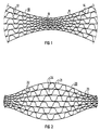
- FIG. 2 shows the case of a sheet metal stack 20 which is positioned opposite to FIG. 1, in which channels 24 with a larger cross-sectional area occur in the central area and channels 23 with a smaller cross-sectional area in the outer areas.
- This stack is also constructed from smooth sheets 21 and from corrugated sheets 22, the corrugation heights and corrugation widths of the corrugated sheets 22 being greater in the central area than in the outer areas.
- the ends of such a stack can also be devoured in opposite directions, for example to fill a honeycomb body, as shown in FIG. 6. It is also possible to build honeycomb bodies from a plurality of such stacks analogously to the prior art.
- a stack of sheets for honeycomb bodies according to the invention can also contain corrugated sheets with the same corrugation height and corrugation width throughout, in particular on the top and bottom of the stack. It is also possible to construct honeycomb bodies from sheet metal stacks which are asymmetrical with respect to their central area, so that different channel cross sections are present in one end area of the stack than in the other end area. In this way, honeycomb bodies can be produced with almost any distribution of the mean channel cross-sections over the cross-sectional area, which can be advantageous for honeycomb bodies with an asymmetrical flow.
- FIGS. 3 and 4 Sheets which are suitable in principle for the construction of honeycomb bodies according to the invention are shown schematically in FIGS. 3 and 4.
- the corrugated sheet 32 shown between two smooth sheet-metal layers 31 has a small corrugation height h1 in area A and changes to a larger corrugation height h2 in transition area B, which continues in area C.
- the corrugated sheet 42 shown between two smooth sheet layers 41 has a corrugation height that increases continuously from left to right.
- FIGS. 3 and 4 can be extended symmetrically at one of their ends to form metal sheets as shown in FIGS. 1 and 2. They can also be continued asymmetrically or with a constant wave height at their ends, depending on the requirements of the honeycomb body to be formed.
- the difference between the small and large well heights and the number of areas with different well heights can also be selected within wide limits. For manufacturing reasons, however, a continuously increasing corrugation height or a sheet with only a few different corrugation heights will be considered.
- a ratio of the well heights h1: h2 from 1: 2 to 1:10, preferably about 1: 4, can be useful. With the preferred ratio, for example, honeycomb bodies can be built which have about 400 cpsi (channels per square inch) in the area of the small channel cross sections, while they have about 100 cpsi in the area of the large channel cross sections.
- corrugations were assumed which can be produced with involute teeth.
- an increase in the corrugation height is always accompanied by a corresponding increase in the mean corrugation width (corresponds to half the division).
- Such a relationship is advantageous for the present invention because of the favorable hydraulic cross sections of such channel shapes, but is not essential.
- the distribution of the channel cross sections according to the invention can also be achieved only by changing the corrugation widths (which results in parallel smooth sheet metal layers) or only by changing the corrugation heights (which can advantageously be produced by intermeshing corrugated rollers at different depths). Any interim solution is also possible.
- FIG. 5 shows a cross section through a honeycomb body, which is built up from three sheet metal stacks, the sheet metal stacks being bent by folding lines in a central region of the honeycomb body.
- the basic production method and the structure of such a honeycomb body are in the above. WO-90/03220.
- the lower part of the honeycomb body shown also corresponds exactly to the structure known there made of smooth 51 and corrugated metal sheets 52, which run approximately in an involute shape and form channels 53.
- the honeycomb body 50 shown shows an embodiment modified according to the invention (separated from the known structure by a broken line) with cross-sections of the channels 54 increasing outwards.
- the smooth 51 and corrugated 52 sheets can be fastened to a casing tube 55, preferably by joining technology by brazing.
- the metal sheets can also be connected to one another in a manner known per se, so that the honeycomb body 50 has the same stability as the honeycomb bodies known from the prior art and filled with metal sheets running in an involute shape.
- a honeycomb body 50 is formed from three or more sheet stacks according to FIG. 1, at least some of the corrugated sheets having different corrugation heights.
- Such honeycomb bodies can also be constructed from stacks according to FIG. It should also be pointed out that this is in no way a restriction to round cross sections, but oval, elliptical or irregular cross sections can also be filled with sheets of different corrugation heights.
- FIG. 6 shows, using the example of an elliptical cross-sectional shape, how a honeycomb body with approximately S-shaped sheet metal layers can be built up from a stack according to FIG.
- This honeycomb body 60 consists of approximately S-shaped smooth 61 and corrugated 62 sheets, which form channels 63 with small cross sections in the outer area and channels 64 with large cross sections in the inner area.
- To complete the honeycomb body 60 include other smooth and corrugated sheets, not shown, the corrugated sheets having the same corrugation height throughout. Round, oval, elliptical cross sections can also be filled well with approximately S-shaped, intertwined sheets, this being possible both with stacks according to FIG. 1 and with stacks according to FIG. 2, depending on whether the larger duct cross sections are desired inside or outside.
- the present invention is of particular importance for unevenly flowed catalyst carrier bodies in exhaust systems of motor vehicles, where a more uniform utilization of the catalytically active volume can be achieved through a corresponding distribution of the channel cross sections over the flowed cross-sectional area of the honeycomb body.
Abstract
Description
Die vorliegende Erfindung betrifft einen Wabenkörper, insbesondere Katalysator-Trägerkörper für Abgassysteme von Verbrennungsmotoren, mit von einem Fluid in einer Strömungsrichtung durchströmbaren Kanälen, der aus einer Vielzahl von einzelnen Blechen aufgebaut ist, von welchen mindestens ein Teil zur Bildung der Kanäle etwa parallel zur Strömungsrichtung verlaufende Strukturen aufweist.The present invention relates to a honeycomb body, in particular a catalyst carrier body for exhaust systems of internal combustion engines, with channels through which a fluid can flow in a flow direction and which is constructed from a multiplicity of individual sheets, at least some of which run approximately parallel to the flow direction to form the channels Has structures.
Solche Wabenkörper sind z. B. aus der EP-C-0 245 737 oder aus der EP-C-0 245 738 bekannt. Auch aus der WO-90/03220 ist ein solcher Wabenkörper bekannt, der aus mindestens drei miteinander verschlungenen Stapeln von Blechen aufgebaut ist.Such honeycomb bodies are e.g. B. from EP-C-0 245 737 or from EP-C-0 245 738 known. Such a honeycomb body is also known from WO-90/03220, which is made up of at least three intertwined stacks of sheets.
Allen diesen Körpern ist gemeinsam, daß sie aus einer Vielzahl von einzelnen Blechen bestehen, was z. B. den Vorteil mit sich bringt, daß die Enden der Bleche einzeln befestigt werden können, wodurch sehr stabile Körper entstehen, die zusätzlich noch in ganz verschiedenen Querschnittsformen leicht herstellbar sind. Grundsätzlich ist auch das einfache Aufeinanderschichten von geraden Blechlagen in einer gewünschten Form möglich, was ebenfalls aus dem Stand der Technik bekannt ist.All these bodies have in common that they consist of a large number of individual sheets, which, for. B. has the advantage that the ends of the sheets can be attached individually, creating very stable bodies that are also easy to manufacture in very different cross-sectional shapes. Basically, the simple stacking of straight sheet metal layers in a desired shape is also possible, which is also known from the prior art.
Bei der Verwendung solcher Wabenkörper in einem strömenden Fluid kann aufgrund der Geometrie eines Rohrleitungssystems nicht immer sichergestellt werden, daß ein solcher Wabenkörper über die gesamte Querschnittsfläche gleichmäßig angeströmt wird. Dies ist inbesondere in Abgassystemen von Kraftfahrzeugen ein Problem, da dort keine beliebigen Baulängen und Einbauten zur Vergleichmäßigung der Strömung möglich sind. So kann es beispielsweise vorkommen, daß ein solcher Wabenkörper in seinem Zentralbereich mit höherer Strömungsgeschwindigkeit angeströmt wird als in seinen äußeren Bereichen, was zu einer ungleichmäßigen Ausnutzung seines Volumens, beispielsweise für katalytische Reaktionen, führt. Es sind auch Anwendungsfälle bekannt, bei denen die Anströmung über einen schnecken- oder spiralförmigen Einlaß mit einem Drall erfolgt. Hier kann es vorkommen, daß die äußeren Bereiche mit größerer Geschwindigkeit angeströmt werden als der innere Bereich eines Wabenkörpers.When using such a honeycomb body in a flowing fluid, it cannot always be ensured due to the geometry of a pipeline system that such a honeycomb body is flowed over uniformly over the entire cross-sectional area. This is a problem in particular in exhaust systems of motor vehicles, since there are no lengths and internals to equalize the flow. For example, such a honeycomb body may have a higher flow velocity in its central area than in its outer areas, resulting in a uneven use of its volume, for example for catalytic reactions. Applications are also known in which the inflow takes place via a helical or spiral inlet with a swirl. Here it can happen that the outer areas are flowed at at a higher speed than the inner area of a honeycomb body.
Für den erstgenannten Fall wird in der EP-A-0 336 106 bereits vorgeschlagen, zur Vergleichmäßigung der Beaufschlagung mit einer Fluidströmung den Wabenkörper so auszubilden, daß die Querschnitte der Kanäle mit zunehmendem radialen Abstand von der Mittelachse größer werden. Ausgeführt wird dies anhand eines spiralig aus einem glatten und einem gewellten Blech aufgewickelten Körpers, bei dem die Wellhöhe und Teilung des gewellten Bleches stufenweise oder kontinuierlich zunimmt. Ein solcher Aufbau ist allerdings fertigungstechnisch sehr schwierig zu verwirklichen, da eine kontinuierlich über einer Bandlänge von beispielsweise 5 m zunehmende Wellhöhe äußerst schwierig reproduzierbar herzustellen ist und eine stufenweise zunehmende Wellhöhe das Wechseln von Wellwalzen erfordert und Diskontinuitäten in dem aufzuwickelnden Körper hervorrufen kann.For the former case, EP-A-0 336 106 already suggests that the honeycomb body be designed so that the fluid flow is evened out so that the cross-sections of the channels become larger with increasing radial distance from the central axis. This is carried out using a body spirally wound from a smooth and a corrugated sheet, in which the corrugation height and division of the corrugated sheet increase gradually or continuously. However, such a structure is very difficult to achieve in terms of production technology, since a corrugation height that continuously increases over a strip length of, for example, 5 m is extremely difficult to reproduce and a stepwise increasing corrugation height requires the changing of corrugation rollers and can cause discontinuities in the body to be wound up.
Aufgabe der vorliegenden Erfindung ist es daher, einen Wabenkörper anzugeben, welcher leichter mit hoher Qualität und reproduzierbar herstellbar ist und bei dem gleichzeitig außen und innen unterschiedliche Kanalquerschnitte vorherrschen. Gleichzeitig soll der Wabenkörper gegen mechanische Belastungen stabil sein und eine Anpassung der Verteilung der Kanalgrößen über die Querschnittsfläche nach unterschiedlichsten Anforderungen zulassen.The object of the present invention is therefore to provide a honeycomb body which is easier to produce with high quality and reproducible and in which different channel cross sections prevail at the outside and inside. At the same time, the honeycomb body should be stable against mechanical loads and allow the distribution of the channel sizes over the cross-sectional area to be adapted according to a wide variety of requirements.
Zur Lösung dieser Aufgabe dient ein Wabenkörper mit von einem Fluid in einer Strömungsrichtung durchströmbaren Kanälen, aufgebaut aus einer Vielzahl von einzelnen Blechen, von welchen mindestens ein Teil etwa parallel zur Strömungsrichtung verlaufende Strukturen aufweist, wobei erfindungsgemäß die Strukturen zumindest bei einem Teil dieser strukturierten Bleche sich kontinuierlich oder stufenweise verändernde Strukturhöhen und/oder Strukturbreiten zur Bildung von Kanälen mit unterschiedlichen Querschnittsflächen aufweisen. Entscheidend für die vorliegende Erfindung ist es, daß der Körper aus einer Vielzahl von einzelnen Blechen besteht, die zumindest teilweise nicht in Umfangsrichtung verlaufen und welche ihrerseits dadurch nicht besonders lang sein müssen. So können die Bleche leichter mit sich kontinuierlich oder stufenweise verändernden Strukturhöhen und/oder Strukturbreiten hergestellt werden, beispielsweise durch Wellwalzen mit sich ändernden Strukturhöhen. An dem übrigen Herstellungsprozeß ändert sich gegenüber dem Stand der Technik fast nichts. Die Bleche können zu einem oder mehreren Stapeln geschichtet und dann wie in den oben zitierten Schriften näher beschrieben, zu einem Wabenkörper verschlungen und gegebenenfalls untereinander und/oder mit einem Mantelrohr durch ein geeignetes fügetechnisches Verfahren, insbesondere Hartlöten, verbunden werden. So können Körper mit einem runden, einem ovalen, einem elliptischen oder einem unregelmäßigen Querschnitt ganz analog zum Stand der Technik hergestellt werden, nur mit dem Unterschied, daß zusätzlich unterschiedliche Kanalquerschnitte beliebig über die Querschnittsfläche verteilt werden können.A honeycomb body with channels through which a fluid can flow in a flow direction is used to achieve this object, constructed from a multiplicity of individual sheets, of which has at least some structures running approximately parallel to the direction of flow, the structures according to the invention at least in some of these structured sheets having continuously or step-wise changing structural heights and / or structural widths to form channels with different cross-sectional areas. It is crucial for the present invention that the body consists of a plurality of individual sheets, which at least partially do not run in the circumferential direction and which in turn do not have to be particularly long as a result. In this way, the sheets can be manufactured more easily with continuously or step-wise changing structural heights and / or structural widths, for example by corrugated rolling with changing structural heights. The rest of the manufacturing process changes almost nothing compared to the prior art. The sheets can be layered into one or more stacks and then, as described in more detail in the documents cited above, intertwined to form a honeycomb body and, if appropriate, connected to one another and / or to a jacket tube by means of a suitable joining technique, in particular brazing. For example, bodies with a round, oval, elliptical or irregular cross section can be produced quite analogously to the prior art, only with the difference that different channel cross sections can additionally be distributed over the cross sectional area as desired.
Um die zu verwendenden Wellwalzen oder anderen Mittel zur Strukturierung der Bleche in einer wirtschaftlich vernünftigen Größe zu halten, ist es vorteilhaft, daß die einzelnen Bleche eine maximale Länge haben, die dem zweifachen
Querschnittsumfang des Wabenkörpers entspricht. Noch günstiger ist es, wenn die Bleche sogar eine kleinere Länge als die des Querschnittsumfangs haben. In konkreten Maßen bedeutet dies für typische Größen von Wabenkörpern, daß die einzelnen Bleche kürzer als 50 cm, vorzugsweise kürzer als 30 cm sind. (Mit der Länge eines strukturierten Bleches ist dessen Länge nach der Strukturierung gemeint).In order to keep the corrugated rollers or other means for structuring the sheets to be used in an economically reasonable size, it is advantageous that the individual sheets have a maximum length that is twice that
Corresponds to the cross-sectional circumference of the honeycomb body. It is even cheaper if the sheets are even shorter than the cross-sectional circumference. In concrete dimensions, this means for typical sizes of honeycomb bodies that the individual sheets are shorter than 50 cm, preferably shorter than 30 cm. (With the length of a structured sheet, its length is the Structuring meant).
Die vorliegende Erfindung läßt prinzipiell jedwede Verteilungen, insbesondere auch nicht konzentrische, der unterschiedlichen Kanalquerschnitte über die Querschnittsfläche des Wabenkörpers zu. Es gibt dabei zwei besondere Anwendungsfälle. Einerseits können insbesondere Körper gebildet werden, bei denen in einem äußeren Bereich des Wabenkörpers kleinere Kanäle vorherrschen und in einem inneren Bereich größere Kanäle. Diese Anordnung ist besonders für mit einem Drall angeströmte Wabenkörper zum Ausgleich der unterschiedlichen Strömungsgeschwindigkeiten von Vorteil. Eine andere bevorzugte Möglichkeit ist die, bei der größere Kanäle in einem äußeren Bereich des Wabenkörpers vorherrschen und in einem inneren Bereich kleinere Kanäle. Die Vorteile einer solchen Ausführung sind in der EP-A-0 336 106 beschrieben.In principle, the present invention allows any distributions, in particular also non-concentric, of the different channel cross sections over the cross-sectional area of the honeycomb body. There are two special applications. On the one hand, in particular bodies can be formed in which smaller channels predominate in an outer region of the honeycomb body and larger channels in an inner region. This arrangement is particularly advantageous for honeycomb bodies against which a swirl flows to compensate for the different flow velocities. Another preferred option is that in which larger channels predominate in an outer region of the honeycomb body and smaller channels in an inner region. The advantages of such an embodiment are described in EP-A-0 336 106.
Obwohl die Erfindung sich auf beliebige aus einer Vielzahl von Blechen geschichtete Wabenkörper bezieht, sind doch die nach dem Stand der Technik bekannten Formen mit etwa S-förmigen Blechen wegen ihrer sonstigen Stabilitätseigenschaften besonders gut geeignet. Unter "etwa S-förmig" ist hier insbesondere eine Ausbildung zu verstehen, bei der die Enden eines Stapels von Blechen gegensinnig miteinander verschlungen sind.Although the invention relates to any honeycomb structure layered from a large number of sheets, the shapes known from the prior art with approximately S-shaped sheets are particularly well suited because of their other stability properties. "About S-shaped" is to be understood here in particular to be an embodiment in which the ends of a stack of sheets are intertwined in opposite directions.
Auch eine nach dem Stand der Technik bekannte Form aus drei oder mehr miteinander verschlungenen Blechstapeln, von denen mindestens drei jeweils um Knicklinien geknickt sind, ist besonders flexibel und für eine Anwendung der vorliegenden Erfindung geeignet. Einzelheiten hierzu sind in der WO-90/03220 beschrieben, weshalb nähere Ausführungen hierzu nicht erforderlich erscheinen.A form known from the prior art, consisting of three or more stacks of sheet metal intertwined with one another, at least three of which are each bent by folding lines, is also particularly flexible and suitable for an application of the present invention. Details of this are described in WO-90/03220, which is why further explanations do not appear to be necessary.
Bei den hier als besonders bevorzugt beschriebenen Ausführungsformen sind die strukturierten Bleche bezüglich ihres mittleren Bereiches im allgemeinen, wenn auch nicht notwendigerweise symmetrisch ausgestaltet, so daß sie entweder an den Endbereichen kleinere Strukturhöhen und/oder Strukturbreiten aufweisen als im mittleren Bereich oder umgekehrt, je nach der gewünschten Art des Wabenkörpers. Grundsätzlich ist jedoch jede andere Verteilung der Strukturhöhen und/oder Strukturbreiten über die Länge der Bleche möglich, da von einem erfindungsgemäßen Wabenkörper nicht gefordert werden muß, daß alle Kanäle in einem bestimmten Querschnittsbereich gleich groß sein müssen. In diesem Sinne ist auch das Wort "vorherrschen" zu verstehen. Es bedeutet nicht, daß alle Kanäle in diesem Bereich die gleiche Größe haben sollen, sondern lediglich, daß eine bestimmte Größe häufiger vorkommen soll als eine andere. So können durchaus einzelne der gewellten Blechlagen durchgehend die gleiche Strukturhöhe aufweisen, solange nur der gewünschte Effekt durch eine genügende Anzahl von Blechlagen mit unterschiedlichen Strukturhöhen erreicht wird.In the embodiments described here as being particularly preferred, the structured sheets are related their central region generally, if not necessarily symmetrically, so that they either have smaller structural heights and / or structural widths at the end regions than in the central region or vice versa, depending on the desired type of honeycomb body. In principle, however, any other distribution of the structure heights and / or structure widths over the length of the metal sheets is possible, since a honeycomb body according to the invention does not have to require that all channels have the same size in a certain cross-sectional area. The word "prevail" should also be understood in this sense. It does not mean that all channels in this area should be the same size, just that one size should be more common than another. Thus, some of the corrugated sheet metal layers can consistently have the same structural height, as long as the desired effect is achieved by a sufficient number of sheet metal layers with different structural heights.
Im allgemeinen werden für Wabenkörper abwechselnd angeordnete glatte und gewellte Bleche verwendet, was auch für die vorliegende Erfindung günstig ist. Andere Ausführungsformen, bei denen alle Bleche Wellungen aufweisen oder die an sich glatten Blechlagen mit einer zusätzlichen parallel oder quer zur Strömungsrichtung verlaufenden Mikrostruktur versehen sind, können ebenfalls angewendet werden.In general, alternating smooth and corrugated sheets are used for honeycomb bodies, which is also favorable for the present invention. Other embodiments in which all the sheets have corrugations or which are in themselves smooth sheet metal layers are provided with an additional microstructure running parallel or transverse to the direction of flow can also be used.
Es sei auch darauf hingewiesen, daß auch Wabenkörper, wie sie im Prinzip beispielsweise in der EP-C-0 245 736 beschrieben sind durch Verwendung von gewellten Blechen mit sich ändernder Strukturhöhe und/oder Strukturbreite modifiziert werden können. Auf diese Weise entstehen Wabenkörper, deren Blechlagen nicht mehr ideal den Formen einer Kreisevolvente folgen, sondern zumindest an Stellen, wo sich die Wellhöhen ändern, von dieser Form abweichen. Die grundsätzlichen Vorteile dieser Anordnung bleiben jedoch erhalten.It should also be pointed out that honeycomb bodies, as described in principle, for example, in EP-C-0 245 736, can also be modified by using corrugated sheets with changing structural height and / or structural width. This creates honeycomb bodies whose sheet metal layers no longer ideally follow the shape of a circular involute, but at least in places where the wave heights change, deviate from this shape. However, the basic advantages of this arrangement are retained.
Ausführungsbeispiele der Erfindung werden im folgenden anhand der Zeichnung näher erläutert. Es zeigen jeweils im Querschnitt und teilweise in schematisierter Form
- Figur 1 einen Teil eines Blechstapels, wie er für Wabenkörper nach Figur 5 Verwendung findet,
- Figur 2 einen Teil eines Blechstapels, wie er für Wabenkörper nach Figur 6 Verwendung findet,
- Figur 3 eine Blechlage mit zwei unterschiedlichen Wellhöhen und Wellbreiten und einem kontinuierlichen Übergang zwischen beiden,
- Figur 4 eine Blechlage mit sich kontinuierlich ändernder Wellhöhe und Wellbreite,
- Figur 5 einen Wabenkörper mit in einem äußeren Bereich größeren Kanalquerschnitten als in einem inneren Bereich und
- Figur 6 einen elliptischen Wabenkörper mit im Zentralbereich größeren Kanalquerschnitten als in einem äußeren Bereich.
- FIG. 1 shows a part of a sheet metal stack as used for honeycomb bodies according to FIG. 5,
- FIG. 2 shows a part of a sheet metal stack as used for honeycomb bodies according to FIG. 6,
- FIG. 3 shows a sheet metal layer with two different corrugation heights and corrugation widths and a continuous transition between the two,
- FIG. 4 shows a sheet metal layer with a continuously changing corrugation height and corrugation width,
- 5 shows a honeycomb body with channel cross sections larger in an outer area than in an inner area and
- Figure 6 shows an elliptical honeycomb body with larger channel cross-sections in the central area than in an outer area.
Figur 1 zeigt einen Stapel 10 aus abwechselnd angeordneten glatten 11 und gewellten 12 Blechen. Die Länge des Stapels, die Größe und die Zahl der Bleche sind nicht maßstäblich, sondern soll nur zur prinzipiellen Erläuterung dienen. Die gewellten Bleche 12 weisen in ihrem mittleren Bereich eine kleinere Wellhöhe und Wellbreite auf als in ihren äußeren Bereichen, so daß sich im mittleren Bereich Kanäle 13 mit kleinerer Querschnittsfläche ergeben als im äußeren Bereich, wo die Kanäle 14 eine größere Querschnittsfläche aufweisen. Die Enden eines solchen Stapels 10 lassen sich gegensinnig verschlingen, so daß alle Bleche annähernd dem Verlauf eines S folgen, wodurch sich Wabenkörper verschiedener Querschnitte herstellen lassen. Hierbei ändert sich nichts Grundsätzliches gegenüber dem Stand der Technik, bei dem das Verschlingen solcher Blechstapel für aus parallelen Lagen bestehende Stapel bekannt ist. Aus mehreren solchen Stapeln 10 läßt sich, wenn diese in ihrem mittleren Bereich um eine Knicklinie geknickt werden, auch ein Körper herstellen, wie er beispielhaft in Figur 5 im Querschnitt dargestellt ist. Auch hier ändert sich gegenüber dem bekannten Herstellungsprinzip für parallele Blechlagen fertigungstechnisch wenig.Figure 1 shows a
Figur 2 zeigt den zu Figur 1 entgegengesetzt gelagerten Fall eines Blechstapels 20, bei dem im mittleren Bereich Kanäle 24 mit größerer Querschnittsfläche und in den äußeren Bereichen Kanäle 23 mit kleinerer Querschnittsfläche auftreten. Auch dieser Stapel ist aus glatten Blechen 21 und aus gewellten Blechen 22 aufgebaut, wobei die Wellhöhen und Wellbreiter der gewellten Bleche 22 im mittleren Bereich größer als in den äußeren Bereichen sind. Auch die Enden eines solchen Stapels lassen sich gegensinnig verschlingen, um beispielsweise einen Wabenkörper, wie in Figur 6 dargestellt, auszufüllen. Auch der Aufbau von Wabenkörpern aus mehreren solchen Stapeln analog zum Stand der Technik ist möglich.FIG. 2 shows the case of a
Es sei darauf hingewiesen, daß ein Stapel von Blechen für erfindungsgemäße Wabenkörper durchaus auch gewellte Bleche mit durchgehend gleicher Wellhöhe und Wellbreite enthalten kann, insbesondere an der Ober- und Unterseite des Stapels. Auch ist es möglich, Wabenkörper aus Blechstapeln aufzubauen, welche unsymmetrisch bezüglich ihres mittleren Bereiches sind, so daß in einem Endbereich des Stapels andere Kanalquerschnitte vorliegen als in dem anderen Endbereich. Auf diese Weise lassen sich Wabenkörper mit nahezu beliebiger Verteilung der mittleren Kanalquerschnitte über die Querschnittsfläche herstellen, was für unsymmetrisch angeströmte Wabenkörper von Vorteil sein kann.It should be pointed out that a stack of sheets for honeycomb bodies according to the invention can also contain corrugated sheets with the same corrugation height and corrugation width throughout, in particular on the top and bottom of the stack. It is also possible to construct honeycomb bodies from sheet metal stacks which are asymmetrical with respect to their central area, so that different channel cross sections are present in one end area of the stack than in the other end area. In this way, honeycomb bodies can be produced with almost any distribution of the mean channel cross-sections over the cross-sectional area, which can be advantageous for honeycomb bodies with an asymmetrical flow.
Prinzipiell für den Aufbau erfindungsgemäßer Wabenkörper geeignete Bleche sind schematisch in den Figuren 3 und 4 dargestellt. In Figur 3 hat das zwischen zwei glatten Blechlagen 31 dargestellte gewellte Blech 32 in dem Bereich A eine kleine Wellhöhe hl und geht in dem Ubergangsbereich B zu einer größeren Wellhöhe h2 über, welche sich im Bereich C fortsetzt.Sheets which are suitable in principle for the construction of honeycomb bodies according to the invention are shown schematically in FIGS. 3 and 4. In FIG. 3, the
In Figur 4 hat das zwischen zwei glatten Blechlagen 41 dargestellte gewellte Blech 42 eine kontinuierlich von links nach rechts zunehmende Wellhöhe.In FIG. 4, the
Die in den Figuren 3 und 4 dargestellten Ausführungsformen können an jeweils einem ihrer Enden symmetrisch verlängert werden, um Bleche wie in den Figuren 1 und 2 dargestellt zu bilden. Sie können auch unsymmetrisch oder mit jeweils konstanter Wellhöhe an ihren Enden weitergeführt werden, je nach den Anforderungen an den zu bildenden Wabenkörper. Der Unterschied zwischen den kleinen und großen Wellhöhen und die Zahl der Bereiche mit unterschiedlichen Wellhöhen ist ebenfalls in weiten Grenzen wählbar. Aus fertigungstechnischen Gründen wird jedoch eher eine kontinuierlich zunehmende Wellhöhe oder ein Blech mit nur wenigen unterschiedlichen Wellhöhen in Betracht kommen. Sinnvoll kann ein Verhältnis der Wellhöhen h1:h2 von 1:2 bis 1:10, vorzugsweise etwa 1:4 sein. Mit dem bevorzugten Verhältnis lassen sich beispielsweise Wabenkörper bauen, welche im Bereich der kleinen Kanalquerschnitte etwa 400 cpsi (Kanäle pro Quadratinch) aufweisen, während sie im Bereich der großen Kanalquerschnitte etwa 100 cpsi haben.The embodiments shown in FIGS. 3 and 4 can be extended symmetrically at one of their ends to form metal sheets as shown in FIGS. 1 and 2. They can also be continued asymmetrically or with a constant wave height at their ends, depending on the requirements of the honeycomb body to be formed. The difference between the small and large well heights and the number of areas with different well heights can also be selected within wide limits. For manufacturing reasons, however, a continuously increasing corrugation height or a sheet with only a few different corrugation heights will be considered. A ratio of the well heights h1: h2 from 1: 2 to 1:10, preferably about 1: 4, can be useful. With the preferred ratio, for example, honeycomb bodies can be built which have about 400 cpsi (channels per square inch) in the area of the small channel cross sections, while they have about 100 cpsi in the area of the large channel cross sections.
Bei den hier beschriebenen Ausführungsbeispielen wurde von Wellungen ausgegangen, die mit einer Evolventenverzahnung herstellbar sind. Bei solchen etwa sinusförmigen Wellungen geht eine Vergrößerung der Wellhöhe immer mit einer entsprechenden Vergrößerung der mittleren Wellbreite (entspricht der halben Teilung) einher. Ein solcher Zusammenhang ist für die vorliegende Erfindung zwar wegen der günstigen hydraulischen Querschnitte solcher Kanalformen vorteilhaft, jedoch nicht zwingend. Die erfindungsgemäße Verteilung der Kanalquerschnitte kann auch nur durch Veränderung der Wellbreiten (was parallele glatte Blechlagen zur Folge hat) oder nur durch Veränderung der Wellhöhen (was durch unterschiedlich tiefes Ineinandergreifen von Wellwalzen vorteilhaft herstellbar ist) erreicht werden. Auch jede Zwischenlösung ist möglich.In the exemplary embodiments described here, corrugations were assumed which can be produced with involute teeth. In the case of such sinusoidal corrugations, an increase in the corrugation height is always accompanied by a corresponding increase in the mean corrugation width (corresponds to half the division). Such a relationship is advantageous for the present invention because of the favorable hydraulic cross sections of such channel shapes, but is not essential. The distribution of the channel cross sections according to the invention can also be achieved only by changing the corrugation widths (which results in parallel smooth sheet metal layers) or only by changing the corrugation heights (which can advantageously be produced by intermeshing corrugated rollers at different depths). Any interim solution is also possible.
Figur 5 zeigt einen Querschnitt durch einen Wabenkörper, der aus drei Blechstapeln aufgebaut ist, wobei die Blechstapel in einem Zentralbereich des Wabenkörpers um Knicklinien geknickt sind. Die prinzipielle Herstellungsweise und der Aufbau eines solchen Wabenkörpers sind in der o. g. WO-90/03220 beschrieben. Der untere Teil des dargestellten Wabenkörpers entspricht auch genau dem dort bekannten Aufbau aus glatten 51 und gewellten Blechen 52, welche etwa evolventenförmig verlaufen und Kanäle 53 bilden. Im oberen Bereich zeigt der dargestellte Wabenkörper 50 jedoch eine erfindungsgemäß geänderte Ausführungsform (durch eine gebrochene Linie von dem bekannten Aufbau getrennt) mit nach außen zunehmenden Querschnitten der Kanäle 54. Die glatten 51 und gewellten 52 Bleche können an einem Mantelrohr 55 fügetechnisch befestigt sein, vorzugsweise durch Hartlöten. Auch untereinander können die Bleche in an sich bekannter Weise verbunden sein, so daß der Wabenkörper 50 die gleiche Stabilität aufweist wie die nach dem Stand der Technik bekannten, mit evolventenförmig verlaufenden Blechen ausgefüllten Wabenkörper. Fertigungstechnisch entsteht ein solcher Wabenkörper 50 aus drei oder mehr Blechstapeln gemäß Figur 1, wobei zumindest ein Teil der gewellten Bleche unterschiedliche Wellhöhen aufweist. Auch aus Stapeln gemäß Figur 2 lassen sich derartige Wabenkörper aufbauen. Es sei auch darauf hingewiesen, daß dabei keineswegs eine Beschränkung auf runde Querschnitte erforderlich ist, sondern auch ovale, elliptische oder unregelmäßige Querschnitte mit Blechen unterschieglicher Wellhöhe ausgefüllt werden können.FIG. 5 shows a cross section through a honeycomb body, which is built up from three sheet metal stacks, the sheet metal stacks being bent by folding lines in a central region of the honeycomb body. The basic production method and the structure of such a honeycomb body are in the above. WO-90/03220. The lower part of the honeycomb body shown also corresponds exactly to the structure known there made of smooth 51 and
Figur 6 zeigt am Beispiel einer elliptischen Querschnittsform, wie sich aus einem Stapel gemäß Figur 2 durch gegensinniges Verschlingen der Stapelenden ein Wabenkörper mit etwa S-förmigen Blechlagen aufbauen läßt. Dieser Wabenkörper 60 besteht aus etwa S-förmig verlaufenden glatten 61 und gewellten 62 Blechen, welche im Außenbereich Kanäle 63 mit kleinen Querschnitten und im inneren Bereich Kanäle 64 mit großen Querschnitten bilden. Zur Vervollständigung des Wabenkörpers 60 gehören noch weitere, nicht dargestellte glatte und gewellte Bleche, wobei die gewellten Bleche durchgehend die gleiche Wellhöhe aufweisen. Auch mit etwa S-förmig verschlungenen Blechen lassen sich runde, ovale elliptische Querschnitte gut ausfüllen, wobei dies sowohl mit Stapeln nach Figur 1 wie auch mit Stapeln nach Figur 2 möglich ist, je nachdem, ob innen oder außen die größeren Kanalquerschnitte gewünscht werden.FIG. 6 shows, using the example of an elliptical cross-sectional shape, how a honeycomb body with approximately S-shaped sheet metal layers can be built up from a stack according to FIG. This
Die vorliegende Erfindung hat besondere Bedeutung für ungleichmäßig angeströmte Katalysator-Trägerkörper in Abgasanlagen von Kraftfahrzeugen, wo durch eine entsprechende Verteilung der Kanalquerschnitte über die angeströmte Querschnittsfläche des Wabenkörpers eine gleichmäßigere Ausnutzung des katalytisch aktiven Volumens erreicht werden kann.The present invention is of particular importance for unevenly flowed catalyst carrier bodies in exhaust systems of motor vehicles, where a more uniform utilization of the catalytically active volume can be achieved through a corresponding distribution of the channel cross sections over the flowed cross-sectional area of the honeycomb body.
Claims (10)
- A honeycombed body, in particular a catalyst carrier body for exhaust gas systems of combustion engines, having passages (13, 14; 23, 24; 53, 54; 63, 64) through which fluid is able to flow in a flow direction, composed of a plurality of individual metal sheets (11, 12; 21, 22; 31, 32; 41, 42; 51, 52; 61, 62) which are arranged to form one or more stacks and which are intertwined, of which metal sheets at least a part (12; 22; 32; 42; 52; 62) have structures which extend approximately parallel to the flow direction in order to form passages (13, 14; 23, 24; 53, 54; 63, 64), characterised in that the structures, at least with a part of these structured metal sheets (12; 22; 32; 42; 52; 62) have structural heights (h1, h2) and/or structural widths which vary continuously or in stages so as to form passages (13, 14; 23, 24; 53, 54; 63, 64) with varying cross-sectional surfaces.
- A honeycombed body according to Claim 1, characterised in that the metal sheets (11, 12; 21, 22; 31, 32; 41, 42; 51, 52; 61, 62) have a maximum length which corresponds to twice the cross-sectional periphery of the honeycombed body, preferably being less in length than that of the cross-sectional periphery.
- A honeycombed body according to Claim 1, characterised in that the individual metal sheets (11, 12; 21, 22; 31, 32; 41, 42; 51, 52; 61, 62) are shorter than 50 cm, preferably shorter than 30 cm.
- A honeycombed body according to Claim 1, 2 or 3, characterised in that at least a part of the structured metal sheets (22; 62) at the end regions are less in structural height (h1) and/or in structural width than in the central region.
- A honeycombed body according to Claim 1, 2 or 3, characterised in that at least a part of the structured metal sheets (12; 52) at the end regions have a greater structural height (h2) and/or structural width than in the central region.
- A honeycombed body according to Claim 1, 2 or 3, characterised in that the metal sheets (22; 32; 42; 62) are arranged such that smaller passages (23; 63) predominate in an outer region of the honeycombed body and larger passages (24; 64) predominate in an inner region.
- A honeycombed body according to Claim 1, 2 or 3, characterised in that the structured metal sheets (12; 32; 42; 52) are arranged such that larger passages (14; 54) predominate in an outer region of the honeycombed body and smaller passages (13; 53) predominate in an inner region, wherein the inner region can also be disposed eccentrically.
- A honeycombed body according to one of the preceding claims, characterised in that the metal sheets (61, 62) are bent substantially into an approximate S-shaped configuration.
- A honeycombed body according to one of Claims 1 to 8, characterised in that the metal sheets (51, 52) are arranged in three or more intertwined stacks inside the honeycombed body, wherein at least three of the stacks are bent at bend lines.
- A honeycombed body according to one of the preceding claims, characterised in that the metal sheets (11, 12; 21, 22; 31, 32; 41, 42; 51, 52; 61, 62) have alternately arranged substantially smooth (11; 21; 31; 41; 51; 61) and corrugated (12; 22; 32; 42; 52; 62) metal sheets, wherein a part of the corrugated metal sheets (12; 22; 32; 42; 52; 62) has at least two different corrugation heights (h1, h2).
Applications Claiming Priority (2)
| Application Number | Priority Date | Filing Date | Title |
|---|---|---|---|
| DE4025434 | 1990-08-10 | ||
| DE4025434A DE4025434A1 (en) | 1990-08-10 | 1990-08-10 | HONEYCOMB BODY WITH CROSS-SECTIONAL AREAS OF DIFFERENT CHANNEL SIZES, IN PARTICULAR CATALYST SUPPORT BODY |
Publications (2)
| Publication Number | Publication Date |
|---|---|
| EP0542805A1 EP0542805A1 (en) | 1993-05-26 |
| EP0542805B1 true EP0542805B1 (en) | 1994-01-19 |
Family
ID=6412044
Family Applications (1)
| Application Number | Title | Priority Date | Filing Date |
|---|---|---|---|
| EP91914048A Expired - Lifetime EP0542805B1 (en) | 1990-08-10 | 1991-07-29 | Honeycomb body with channels having different cross-sectional dimensions, in particular catalyzer bearing body |
Country Status (5)
| Country | Link |
|---|---|
| EP (1) | EP0542805B1 (en) |
| JP (1) | JPH05509032A (en) |
| DE (2) | DE4025434A1 (en) |
| ES (1) | ES2048016T3 (en) |
| WO (1) | WO1992002717A1 (en) |
Cited By (2)
| Publication number | Priority date | Publication date | Assignee | Title |
|---|---|---|---|---|
| US5865864A (en) * | 1995-02-20 | 1999-02-02 | Emitec Gesellschaft Fuer Emissionstechnologie Mbh | Honeycomb body having channels of different flow resistance through which a fluid can flow and apparatus having the honeycomb body for cleaning exhaust gas |
| US6497130B2 (en) | 2000-02-11 | 2002-12-24 | Kemira Metalkat Oy | Method for corrugating a metal foil and packages of such foil |
Families Citing this family (19)
| Publication number | Priority date | Publication date | Assignee | Title |
|---|---|---|---|---|
| FI94455C (en) * | 1992-08-28 | 1995-09-11 | Kemira Oy | Catalyst and preparation process for the same |
| DE4233404C2 (en) * | 1992-10-05 | 1994-08-18 | Degussa | Monolithic supported metal catalyst with a catalytically coated honeycomb body |
| US5866230A (en) * | 1993-01-11 | 1999-02-02 | Emitec Gesellschaft Fuer Emissionstechnologie Gmbh | Extruded honeycomb body of ceramic and/or metallic material with increased flexibility |
| PL174466B1 (en) * | 1994-09-12 | 1998-07-31 | Huta Baildon | Apparatus for catalytically purifying combustion engine exhaust gas and method of manufacturing such apparatus |
| FR2728303A1 (en) * | 1994-12-16 | 1996-06-21 | Rosi Ets | Spiral winding construction for catalytic converter core |
| DE19514986A1 (en) * | 1995-04-24 | 1996-10-31 | Audi Ag | Catalyser converting harmful exhaust components |
| JP3610720B2 (en) * | 1997-03-03 | 2005-01-19 | 日産自動車株式会社 | Metal catalyst carrier structure |
| DE19740966C2 (en) * | 1997-09-17 | 1999-09-09 | Emitec Emissionstechnologie | Method for producing a metallic carrier body and a metallic carrier body for an exhaust system of an internal combustion engine |
| DE19824428B4 (en) * | 1998-05-30 | 2004-07-01 | Daimlerchrysler Ag | Exhaust gas catalyst body with different, parallel cell structure areas |
| DE19959612A1 (en) * | 1999-12-10 | 2001-06-13 | Volkswagen Ag | Catalyzer body for i.c. engine exhaust gas catalyzer has carrier formed of metal material in low flow resistance area and formed of ceramic material in high flow resistance area |
| DE10057420A1 (en) * | 2000-11-20 | 2002-06-06 | Emitec Emissionstechnologie | Multi-stage shift reactor and reformer system |
| DE10057418A1 (en) * | 2000-11-20 | 2002-06-20 | Emitec Emissionstechnologie | Reactor unit used for steam reforming a gas mixture stream containing hydrocarbons in fuel cells has sheet layers with heating fluid channels and gas mixture channels arranged to form a specified angle |
| DE10329002A1 (en) * | 2003-06-27 | 2005-01-20 | Emitec Gesellschaft Für Emissionstechnologie Mbh | Structure of a metallic honeycomb structure and method for its production |
| DE102005028044A1 (en) | 2005-06-17 | 2006-12-28 | Emitec Gesellschaft Für Emissionstechnologie Mbh | Honeycomb body for after-treatment of exhaust gas in automobile sector has housing and layers with curved gradient and of specific length, which in each case comprises partly structured metal film |
| JP2007196156A (en) * | 2006-01-27 | 2007-08-09 | Calsonic Kansei Corp | Metallic carrier and its manufacturing method |
| CN104879196A (en) * | 2014-02-28 | 2015-09-02 | 重庆江赛环保科技有限公司 | Catalyst with variational mesh numbers |
| DE102014105770A1 (en) * | 2014-04-24 | 2015-11-12 | Emitec Gesellschaft Für Emissionstechnologie Mbh | Method for influencing a fluid flow |
| CN110006071A (en) * | 2018-01-04 | 2019-07-12 | 华帝股份有限公司 | infrared metal honeycomb body, manufacturing method thereof and infrared metal burner |
| CN113982724B (en) * | 2021-10-12 | 2022-12-23 | 台州三元车辆净化器有限公司 | Novel metal honeycomb carrier |
Family Cites Families (13)
| Publication number | Priority date | Publication date | Assignee | Title |
|---|---|---|---|---|
| US3100140A (en) * | 1960-05-31 | 1963-08-06 | Calumet & Hecla | Catalytic automotive exhaust converter |
| DE2514129C3 (en) * | 1975-03-29 | 1979-03-01 | Basf Ag, 6700 Ludwigshafen | Device for achieving a uniform flow profile |
| JPS62174525A (en) * | 1986-01-25 | 1987-07-31 | Toyota Motor Corp | Catalyst convertor |
| EP0232793B1 (en) * | 1986-01-30 | 1990-11-22 | Nippon Steel Corporation | Stainless steel ribbon for use as a catalyst carrier for automobile exhaust gas and method for producing same |
| EP0245737B1 (en) * | 1986-05-12 | 1989-08-23 | INTERATOM Gesellschaft mit beschränkter Haftung | Honeycomb body, particularly a catalyst carrier, provided with opposedly folded metal sheet layers, and its manufacturing process |
| DE8801788U1 (en) * | 1988-02-11 | 1989-06-15 | Emitec Emissionstechnologie | |
| DE8801738U1 (en) * | 1988-02-11 | 1988-03-31 | Kabelmetal Electro Gmbh, 3000 Hannover, De | |
| DE3809105A1 (en) * | 1988-03-18 | 1989-09-28 | Eberspaecher J | DEVICE FOR CATALYTICALLY PURIFYING THE EXHAUST GASES OF AN INTERNAL COMBUSTION ENGINE AND METHOD FOR THE PRODUCTION THEREOF |
| DE3809490C1 (en) * | 1988-03-22 | 1989-05-11 | Sueddeutsche Kuehlerfabrik Julius Fr. Behr Gmbh & Co Kg, 7000 Stuttgart, De | |
| KR940005668B1 (en) * | 1988-08-13 | 1994-06-22 | 우스이 고꾸사이 산교 가부시끼가이샤 | Casing for exhaust gas cleaning catalyst |
| DE58900964D1 (en) * | 1988-09-22 | 1992-04-16 | Emitec Emissionstechnologie | HONEYCOMB BODY, IN PARTICULAR CATALYST CARRIER BODY, FROM A MULTIPLE NUMBER OF PLAID STACKS. |
| JP2745222B2 (en) * | 1988-12-13 | 1998-04-28 | 臼井国際産業株式会社 | Metal base of exhaust gas purification catalyst |
| DE8908738U1 (en) * | 1989-07-18 | 1989-09-07 | Emitec Emissionstechnologie |
-
1990
- 1990-08-10 DE DE4025434A patent/DE4025434A1/en not_active Withdrawn
-
1991
- 1991-07-29 ES ES91914048T patent/ES2048016T3/en not_active Expired - Lifetime
- 1991-07-29 JP JP3512761A patent/JPH05509032A/en active Pending
- 1991-07-29 WO PCT/EP1991/001423 patent/WO1992002717A1/en active IP Right Grant
- 1991-07-29 EP EP91914048A patent/EP0542805B1/en not_active Expired - Lifetime
- 1991-07-29 DE DE91914048T patent/DE59100919D1/en not_active Expired - Fee Related
Cited By (3)
| Publication number | Priority date | Publication date | Assignee | Title |
|---|---|---|---|---|
| US5865864A (en) * | 1995-02-20 | 1999-02-02 | Emitec Gesellschaft Fuer Emissionstechnologie Mbh | Honeycomb body having channels of different flow resistance through which a fluid can flow and apparatus having the honeycomb body for cleaning exhaust gas |
| DE19680093B4 (en) * | 1995-02-20 | 2006-08-24 | Emitec Gesellschaft Für Emissionstechnologie Mbh | Honeycomb body with flow-through channels of different flow resistance |
| US6497130B2 (en) | 2000-02-11 | 2002-12-24 | Kemira Metalkat Oy | Method for corrugating a metal foil and packages of such foil |
Also Published As
| Publication number | Publication date |
|---|---|
| JPH05509032A (en) | 1993-12-16 |
| WO1992002717A1 (en) | 1992-02-20 |
| EP0542805A1 (en) | 1993-05-26 |
| DE4025434A1 (en) | 1992-02-13 |
| ES2048016T3 (en) | 1994-03-01 |
| DE59100919D1 (en) | 1994-03-03 |
Similar Documents
| Publication | Publication Date | Title |
|---|---|---|
| EP0542805B1 (en) | Honeycomb body with channels having different cross-sectional dimensions, in particular catalyzer bearing body | |
| EP0542775B1 (en) | Monolithic metal honeycomb body with varying number of channels | |
| EP0484364B1 (en) | Honeycomb body with internal inflow edges, in particular catalyst body for motor vehicles | |
| EP0386013B1 (en) | Catalyzer with flow guiding body | |
| EP0454712B1 (en) | Metallic honeycomb structure | |
| DE2902779C2 (en) | Matrix for a catalytic reactor for exhaust gas cleaning in internal combustion engines | |
| DE19680093B4 (en) | Honeycomb body with flow-through channels of different flow resistance | |
| EP1848534B1 (en) | Honeycomb with internal cavities | |
| EP0784507B1 (en) | Microstructures in an intersecting arrangement | |
| EP1089819B1 (en) | Monolithic, metallic honeycomb bodies with a number of varying channels | |
| EP0186801A2 (en) | Support matrix, in particular for a catalytic exhaust converter | |
| WO1990003220A1 (en) | Honeycomb structure, in particular catalyst support, composed of a plurality of interlaced bundles of sheet metal | |
| EP0152560A1 (en) | Matrix for a catalytic reactor for purifying exhaust gases | |
| EP0336106B1 (en) | Process for manufacturing a carrier for a catalytic reactor | |
| EP0577117A2 (en) | Process for preparing a catalyst | |
| DE10356997A1 (en) | particulate Filter | |
| DE2428042C3 (en) | Tubular heat exchanger | |
| EP2864604B1 (en) | Conical honeycomb body with radial and oblique orientated flow chanels | |
| EP0762934B1 (en) | Honeycomb body made layers of metallic materials having different thicknesses | |
| DE3844350A1 (en) | Support body for a catalytic reactor for exhaust gas purification | |
| EP1179126A1 (en) | Catalyst supporting body | |
| WO1998033592A1 (en) | Honeycomb body, in particular catalyst support body, with a reinforced wall structure | |
| WO1994015712A1 (en) | Extruded honeycomb elements made of ceramic and/or metallic material with enhanced flexibility | |
| EP3797220B1 (en) | Honeycomb and method for manufacturing the honeycomb | |
| EP3615778B1 (en) | Metallic honeycomb structure with adhesion improving microstructures |
Legal Events
| Date | Code | Title | Description |
|---|---|---|---|
| PUAI | Public reference made under article 153(3) epc to a published international application that has entered the european phase |
Free format text: ORIGINAL CODE: 0009012 |
|
| 17P | Request for examination filed |
Effective date: 19921126 |
|
| AK | Designated contracting states |
Kind code of ref document: A1 Designated state(s): DE ES FR GB IT SE |
|
| 17Q | First examination report despatched |
Effective date: 19930701 |
|
| GRAA | (expected) grant |
Free format text: ORIGINAL CODE: 0009210 |
|
| AK | Designated contracting states |
Kind code of ref document: B1 Designated state(s): DE ES FR GB IT SE |
|
| REG | Reference to a national code |
Ref country code: ES Ref legal event code: FG2A Ref document number: 2048016 Country of ref document: ES Kind code of ref document: T3 |
|
| REF | Corresponds to: |
Ref document number: 59100919 Country of ref document: DE Date of ref document: 19940303 |
|
| ITF | It: translation for a ep patent filed |
Owner name: STUDIO JAUMANN |
|
| GBT | Gb: translation of ep patent filed (gb section 77(6)(a)/1977) |
Effective date: 19940323 |
|
| ET | Fr: translation filed | ||
| PLBE | No opposition filed within time limit |
Free format text: ORIGINAL CODE: 0009261 |
|
| STAA | Information on the status of an ep patent application or granted ep patent |
Free format text: STATUS: NO OPPOSITION FILED WITHIN TIME LIMIT |
|
| 26N | No opposition filed | ||
| EAL | Se: european patent in force in sweden |
Ref document number: 91914048.3 |
|
| PGFP | Annual fee paid to national office [announced via postgrant information from national office to epo] |
Ref country code: SE Payment date: 19960719 Year of fee payment: 6 |
|
| PGFP | Annual fee paid to national office [announced via postgrant information from national office to epo] |
Ref country code: ES Payment date: 19960729 Year of fee payment: 6 |
|
| PG25 | Lapsed in a contracting state [announced via postgrant information from national office to epo] |
Ref country code: SE Effective date: 19970730 Ref country code: ES Free format text: LAPSE BECAUSE OF THE APPLICANT RENOUNCES Effective date: 19970730 |
|
| EUG | Se: european patent has lapsed |
Ref document number: 91914048.3 |
|
| REG | Reference to a national code |
Ref country code: ES Ref legal event code: FD2A Effective date: 20001009 |
|
| REG | Reference to a national code |
Ref country code: GB Ref legal event code: IF02 |
|
| PGFP | Annual fee paid to national office [announced via postgrant information from national office to epo] |
Ref country code: DE Payment date: 20080729 Year of fee payment: 18 |
|
| PGFP | Annual fee paid to national office [announced via postgrant information from national office to epo] |
Ref country code: FR Payment date: 20080722 Year of fee payment: 18 Ref country code: IT Payment date: 20080728 Year of fee payment: 18 |
|
| PGFP | Annual fee paid to national office [announced via postgrant information from national office to epo] |
Ref country code: GB Payment date: 20080723 Year of fee payment: 18 |
|
| GBPC | Gb: european patent ceased through non-payment of renewal fee |
Effective date: 20090729 |
|
| REG | Reference to a national code |
Ref country code: FR Ref legal event code: ST Effective date: 20100331 |
|
| PG25 | Lapsed in a contracting state [announced via postgrant information from national office to epo] |
Ref country code: FR Free format text: LAPSE BECAUSE OF NON-PAYMENT OF DUE FEES Effective date: 20090731 |
|
| PG25 | Lapsed in a contracting state [announced via postgrant information from national office to epo] |
Ref country code: GB Free format text: LAPSE BECAUSE OF NON-PAYMENT OF DUE FEES Effective date: 20090729 |
|
| PG25 | Lapsed in a contracting state [announced via postgrant information from national office to epo] |
Ref country code: DE Free format text: LAPSE BECAUSE OF NON-PAYMENT OF DUE FEES Effective date: 20100202 |
|
| PG25 | Lapsed in a contracting state [announced via postgrant information from national office to epo] |
Ref country code: IT Free format text: LAPSE BECAUSE OF NON-PAYMENT OF DUE FEES Effective date: 20090729 |