DE102012103025A1 - siphon - Google Patents
siphon Download PDFInfo
- Publication number
- DE102012103025A1 DE102012103025A1 DE102012103025A DE102012103025A DE102012103025A1 DE 102012103025 A1 DE102012103025 A1 DE 102012103025A1 DE 102012103025 A DE102012103025 A DE 102012103025A DE 102012103025 A DE102012103025 A DE 102012103025A DE 102012103025 A1 DE102012103025 A1 DE 102012103025A1
- Authority
- DE
- Germany
- Prior art keywords
- valve
- siphon
- outlet opening
- inlet
- siphon according
- Prior art date
- Legal status (The legal status is an assumption and is not a legal conclusion. Google has not performed a legal analysis and makes no representation as to the accuracy of the status listed.)
- Ceased
Links
Images


Classifications
-
- E—FIXED CONSTRUCTIONS
- E03—WATER SUPPLY; SEWERAGE
- E03C—DOMESTIC PLUMBING INSTALLATIONS FOR FRESH WATER OR WASTE WATER; SINKS
- E03C1/00—Domestic plumbing installations for fresh water or waste water; Sinks
- E03C1/12—Plumbing installations for waste water; Basins or fountains connected thereto; Sinks
- E03C1/28—Odour seals
- E03C1/298—Odour seals consisting only of non-return valve
-
- E—FIXED CONSTRUCTIONS
- E03—WATER SUPPLY; SEWERAGE
- E03D—WATER-CLOSETS OR URINALS WITH FLUSHING DEVICES; FLUSHING VALVES THEREFOR
- E03D13/00—Urinals ; Means for connecting the urinal to the flushing pipe and the wastepipe; Splashing shields for urinals
- E03D13/007—Waterless or low-flush urinals; Accessories therefor
-
- E—FIXED CONSTRUCTIONS
- E03—WATER SUPPLY; SEWERAGE
- E03F—SEWERS; CESSPOOLS
- E03F5/00—Sewerage structures
- E03F5/04—Gullies inlets, road sinks, floor drains with or without odour seals or sediment traps
- E03F2005/0412—Gullies inlets, road sinks, floor drains with or without odour seals or sediment traps with means for adjusting their position with respect to the surrounding surface
- E03F2005/0415—Gullies inlets, road sinks, floor drains with or without odour seals or sediment traps with means for adjusting their position with respect to the surrounding surface for horizontal position adjustment
-
- E—FIXED CONSTRUCTIONS
- E03—WATER SUPPLY; SEWERAGE
- E03F—SEWERS; CESSPOOLS
- E03F5/00—Sewerage structures
- E03F5/04—Gullies inlets, road sinks, floor drains with or without odour seals or sediment traps
- E03F2005/0416—Gullies inlets, road sinks, floor drains with or without odour seals or sediment traps with an odour seal
- E03F2005/0417—Gullies inlets, road sinks, floor drains with or without odour seals or sediment traps with an odour seal in the form of a valve
Landscapes
- Engineering & Computer Science (AREA)
- Health & Medical Sciences (AREA)
- Life Sciences & Earth Sciences (AREA)
- Hydrology & Water Resources (AREA)
- Public Health (AREA)
- Water Supply & Treatment (AREA)
- Environmental & Geological Engineering (AREA)
- Sanitary Device For Flush Toilet (AREA)
- Sink And Installation For Waste Water (AREA)
- Domestic Plumbing Installations (AREA)
Abstract
Ein Siphon, insbesondere Geruchsverschluss für ein wasserloses Urinal oder einen Bodenablauf, umfasst einen rohrförmigen Einlauf (1) und mindestens einen Auslauf (2), dessen Auslassöffnung (3) mittels eines Ventils (4) gegenüber einem anschließbaren Abfluss zu öffnen und schließen ist. Das Ventil (4) umfasst einen im Bereich des Einlaufs (1) gelenkig gelagerten Ventilhebel (6) mit einer zugeordneten Ventilfläche (7), wobei die Ventilfläche (7) die Auslassöffnung (3) form- und/oder kraftschlüssig abdichtend verschließt.A siphon, in particular an odor trap for a waterless urinal or a floor drain, comprises a tubular inlet (1) and at least one outlet (2) whose outlet opening (3) can be opened and closed by means of a valve (4) with respect to a connectable drain. The valve (4) comprises a valve lever (6) articulated in the region of the inlet (1) with an associated valve surface (7), wherein the valve surface (7) sealingly closes the outlet opening (3) in a positive and / or non-positive manner.
Description
Die Erfindung bezieht sich auf einen Siphon, insbesondere Geruchsverschluss für ein Urinal oder einen Bodenablauf, mit einem rohrförmigen Einlauf und mindestens einem Auslauf, dessen Auslassöffnung mittels eines Ventils gegen- über einem anschließbaren Abfluss zu öffnen und schließen ist. The invention relates to a siphon, in particular odor trap for a urinal or a floor drain, with a tubular inlet and at least one outlet whose outlet opening is to open and close by means of a valve compared to a connectable drain.
Die
Im Weiteren zeigt die
Der Erfindung liegt die Aufgabe zugrunde, einen Siphon, der eingangs genannten Art zu schaffen, der zur Vermeidung austretender Gerüche zuverlässig verschließbar ist. The invention has for its object to provide a siphon of the type mentioned, which is reliably closed to prevent escaping odors.
Erfindungsgemäß wird die Aufgabe durch die Merkmale des Anspruchs 1 gelöst. According to the invention the object is achieved by the features of
Die Unteransprüche stellen vorteilhafte Ausgestaltungen der Erfindung dar. The subclaims represent advantageous embodiments of the invention.
Ein Siphon, insbesondere Geruchsverschluss für ein Urinal oder einen Bodenablauf, umfasst einen rohrförmigen Einlauf und mindestens einen Auslauf, dessen Auslassöffnung mittels eines Ventils gegenüber einem anschließbaren Abfluss zu öffnen und schließen ist. Das Ventil umfasst einen im Bereich des Einlaufs gelenkig gelagerten Ventilhebel mit einer zugeordneten Ventilfläche, wobei die Ventilfläche die Auslassöffnung form- und/oder kraftschlüssig abdichtend verschließt. A siphon, in particular odor trap for a urinal or a floor drain, comprises a tubular inlet and at least one outlet whose outlet opening is to be opened and closed by means of a valve with respect to a connectable drain. The valve comprises a valve lever articulated in the region of the inlet with an associated valve surface, wherein the valve surface closes the outlet opening in a positive and / or non-positive sealing manner.
Bevorzugt weist der Auslauf mit seiner Auslassöffnung in Gebrauchslage in eine gegenüber dem Einlauf seitlich ausgerichtete Richtung. Preferably, the outlet with its outlet opening in the use position in a direction opposite to the inlet laterally aligned direction.
Wenn keine Flüssigkeit durch den Siphon strömt, liegt die Ventilfläche derart über der Auslassöffnung, dass diese luftdicht verschlossen ist, sodass kein Geruch aus einem Kanal, an den der Siphon angeschlossen ist, durch den Siphon austritt. Die Ventilfläche, die eine an die Auslassöffnung bzw. den Auslauf angepasste Kontur aufweist, wird aufgrund der Gewichtskraft, insbesondere des Ventilhebels, dichtend angedrückt, wobei zur Erzeugung eines entsprechenden Momentes die Position des Gelenkes, die Länge des Ventilhebels sowie die Gewichtsverteilung geeignet gewählt wird, um einen möglichst großen Druck auf die Ventilfläche auszuüben und gleichzeitig einen Austritt von Flüssigkeit, auch in geringster Menge, durch den auf die Ventilfläche wirkenden Druck der Flüssigkeit zum Öffnen der Auslassöffnung sicherzustellen. Die abdichtende Ventilfläche kann unmittelbar an dem Ventilhebel ausgebildet oder einem mit dem Ventilhebel verbundenen Bauteil zugeordnet sein. Selbstverständlich kann der Einlauf mit einer geschlitzten oder gelochten Abdeckung versehen sein, die ein Eindringen von möglicherweise zu einer Verstopfung des Siphons führenden Gegenständen verhindert. Die Ausrichtung der Auslassöffnung in einer Gebrauchslage des Siphons erfolgt strömungstechnisch zweckmäßig, um Flüssigkeit abzuleiten. If there is no liquid flowing through the siphon, the valve face is over the outlet opening in such a way that it is hermetically sealed, so that no odor from a channel to which the siphon is connected exits through the siphon. The valve surface, which has a contour adapted to the outlet opening or the outlet, is pressed in a sealing manner due to the weight force, in particular of the valve lever, the position of the joint, the length of the valve lever and the weight distribution being suitably selected for generating a corresponding moment. to exert the greatest possible pressure on the valve surface and at the same time to ensure a leakage of liquid, even in the smallest amount, by acting on the valve surface pressure of the liquid to open the outlet opening. The sealing valve surface may be formed directly on the valve lever or assigned to a component connected to the valve lever. Of course, the inlet can be provided with a slotted or perforated cover, which prevents the ingress of possibly leading to clogging of the siphon objects. The alignment of the outlet opening in a position of use of the siphon is fluidly appropriate to dissipate liquid.
Zur Erhöhung der Dichtwirkung ist vorzugsweise zwischen der Ventilfläche und einer Dichtfläche des Auslaufs eine Dichtung angeordnet, die insbesondere ringförmig die Auslassöffnung umschließt und vorzugsweise aus einem Elastomer gefertigt ist. Die Dichtung kann als sogenannter Dichtgummi vollflächig die Ventilfläche überdecken oder als ringförmige Dichtung auf der Ventilfläche oder der Dichtfläche angeordnet sein. Zweckmäßigerweise weisen die Ventilfläche und die Dichtfläche korrespondierende Geometrien auf, insbesondere stimmen die äußere Dichtfläche und die innere Ventilfläche oder umgekehrt überein. To increase the sealing effect, a seal is preferably arranged between the valve surface and a sealing surface of the outlet, which encloses in particular annularly the outlet opening and is preferably made of an elastomer. As a so-called sealing rubber, the seal can cover the entire surface of the valve surface or be arranged as an annular seal on the valve surface or the sealing surface. Appropriately wise the valve surface and the sealing surface corresponding geometries, in particular, the outer sealing surface and the inner valve surface or vice versa match.
Um die Auslassöffnung auch in einer relativ ungünstigen Gebrauchslage besonders zuverlässig zu verschließen, ist der Ventilhebel und/oder der Ventildeckel durch ein Betätigungsglied, insbesondere eine Feder, eine Elektromagneteinrichtung, eine Kolben-Zylinder-Anordnung, zum Öffnen und/oder Schließen der Auslassöffnung beaufschlagt. In order to close the outlet opening particularly reliably even in a relatively unfavorable position of use, the valve lever and / or the valve cover is acted upon by an actuating member, in particular a spring, an electromagnetic device, a piston-cylinder arrangement for opening and / or closing the outlet opening.
In Ausgestaltung ist die Ventilfläche Bestandteil einer mit dem Ventilhebel verbundenen Ventilklappe. Vorteilhafterweise ist die Ventilklappe, vorzugsweise über ein Gelenk, mit einem freien Ende des Ventilhebels derart gekoppelt ist, dass er sich zu beiden Seiten des Gelenkes zwischen dem Ventilhebel und dem Siphon sowie über das freie Ende des Ventilhebels hinaus oder auf einer Seite des Gelenkes zwischen dem Ventilhebel und dem Siphon erstreckt. Die Anordnung des Lagers zwischen der Ventilklappe und dem Ventilhebel wird in Abhängigkeit von der Geometrie des Siphons bzw. der Auslassöffnung gewählt. Das Gelenk kann derart gestaltet sein, dass die Ventilklappe und/oder der Ventilhebel auswechselbar sind. In an embodiment, the valve surface is part of a valve flap connected to the valve lever. Advantageously, the valve flap, preferably via a hinge, is coupled to a free end of the valve lever such that it extends either side of the joint between the valve lever and the siphon and over the free end of the valve lever or on one side of the joint between the valve Valve lever and the siphon extends. The arrangement of the bearing between the valve flap and the valve lever is chosen depending on the geometry of the siphon or the outlet opening. The joint may be designed such that the valve flap and / or the valve lever are replaceable.
Da jedes Gelenk lediglich einen Freiheitsgrad benötigt, damit die beiden gelenkig miteinander verbundenen Bauteile relativ zueinander verschwenkbar sind, ist vorzugsweise das Gelenk zwischen dem Siphon und dem Ventilhebel und/oder zwischen dem Ventilhebel und der Ventilplatte als ein Scharniergelenk ausgebildet. Beispielsweise können Trägerachsstummel in entsprechenden gabelförmigen Klipsaufnahmen drehbar gelagert sein. Since each joint requires only one degree of freedom, so that the two articulated components are pivotable relative to each other, preferably the joint between the siphon and the valve lever and / or between the valve lever and the valve plate is designed as a hinge joint. For example, carrier stub axles can be rotatably mounted in corresponding fork-shaped clip receivers.
Um eine zuverlässige Anlage der Ventilplatte zum luftdichten Verschließen der Auslassöffnung sicherzustellen, ist zwischen dem Ventilhebel und der Ventilplatte mindestens eine zum Verschließen der Auslassöffnung wirksame Distanznocke angeordnet. Die beispielsweise an dem Ventilhebel vorgesehene Distanznocke übt beabstandet zu dem Gelenk Druck auf die Ventilplatte in Richtung der Auslassöffnung aus. In order to ensure reliable installation of the valve plate for airtight closing of the outlet opening, at least one effective distance cam for closing the outlet opening is arranged between the valve lever and the valve plate. The distance cam provided, for example, on the valve lever exerts pressure on the valve plate at a distance from the joint in the direction of the outlet opening.
Zweckmäßigerweise ist das Gelenk im Bereich des Einlaufs an einer Klammer ausgebildet, die, insbesondere kraftschlüssig, an dem Siphon angreift, wobei sich der Ventilhebel und die Ventilklappe auf der Außenseite des Siphons erstrecken. Die Klammer kann einfach im Bereich des Einlaufs angeklipst werden und ist leicht auswechselbar. Conveniently, the joint is formed in the region of the inlet to a clamp which, in particular frictionally engages the siphon, wherein the valve lever and the valve flap extend on the outside of the siphon. The clip can easily be clipped in the area of the inlet and is easily replaceable.
Nach einer Weiterbildung ist die Dichtfläche in ihrer Längserstreckung konvex gekrümmt. According to a development, the sealing surface is convexly curved in its longitudinal extent.
Bevorzugt ist der Einlauf durch eine stirnseitige Öffnung eines Rohres gebildet, das in seinem weiteren Verlauf mindestens einen Bogen aufweist, dessen freies Ende die Auslassöffnung bildet, die bevorzugt von der Dichtfläche umgeben ist. Dementsprechend umfasst der Siphon kein Gehäuse und die Flüssigkeit durchströmt quasi einen Rohrbogen, der stirnseitig durch das Ventil verschließbar ist. Sollen mehrere Auslassöffnungen bereitgestellt werden, ist es möglich, den Einlass in eine entsprechende Anzahl Rohrbögen zu verzweigen. Preferably, the inlet is formed by an end opening of a tube, which has in its further course at least one arc whose free end forms the outlet opening, which is preferably surrounded by the sealing surface. Accordingly, the siphon comprises no housing and the liquid flows through quasi a pipe bend, which is closed by the end face of the valve. If several outlet openings are to be provided, it is possible to branch the inlet into a corresponding number of pipe bends.
In weiterer Ausgestaltung verläuft das Rohr Y-förmig. Das Rohr umfasst also einen Einlass und zwei in etwa gegenüberliegende Auslassöffnungen. Selbstverständlich ist auch die Ausgestaltung weiterer Auslassöffnungen, die sich in radialer Richtung erstrecken möglich und liegt im Rahmen der Erfindung. In a further embodiment, the tube is Y-shaped. The tube thus comprises an inlet and two approximately opposite outlet openings. Of course, the configuration of further outlet openings, which extend in the radial direction is possible and is within the scope of the invention.
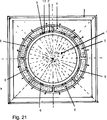
Insbesondere im Zusammenhang mit einem Ablauf eines Waschbeckens oder eines Bodeneinlaufs ist der Einlauf durch eine stirnseitige Öffnung eines Rohres gebildet, dessen gegenüberliegende Stirnseite, von der sich ein Kegel oder eine Pyramide in das Innere des Rohres erstreckt verschlossen ist, wobei im Bereich der verschlossenen Stirnseite umfangsseitig mindestens eine Auslassöffnung ausgebildet ist. In particular, in connection with a drain of a sink or a bottom inlet of the inlet is formed by an end opening of a tube whose opposite end face, from which a cone or a pyramid extends into the interior of the tube is closed, in the region of the closed end side circumferentially at least one outlet opening is formed.
Zur relativ schnellen Ableitung einer verhältnismäßig großen Flüssigkeitsmenge weist der Einlauf einen bauchigen Querschnitt auf. For relatively fast discharge of a relatively large amount of liquid, the inlet has a bulbous cross-section.
Der zuvor erläuterte Siphon wird bevorzugt an einem, insbesondere wasserlosen, Urinal oder einem Bodenablauf oder einem Bidet oder einem Waschbecken verwendet. Selbstverständlich ist sein Einsatz stets zweckmäßig, wenn ein Geruchsverschluss, insbesondere gegenüber einem Kanal, vorgesehen sein soll und eine flüssige Sperrschicht nicht vorhanden ist. The previously described siphon is preferably used on a, in particular waterless, urinal or a floor drain or a bidet or a sink. Of course, its use is always useful when an odor trap, especially against a channel, should be provided and a liquid barrier layer is not present.
Es versteht sich, dass die vorstehend genannten und nachstehend noch zu erläuternden Merkmale nicht nur in der jeweils angegebenen Kombination, sondern auch in anderen Kombinationen verwendbar sind. Der Rahmen der Erfindung ist nur durch die Ansprüche definiert. It goes without saying that the features mentioned above and those yet to be explained below can be used not only in the respectively specified combination but also in other combinations. The scope of the invention is defined only by the claims.
Die Erfindung wird im Folgenden anhand mehrerer Ausführungsbeispiele unter Bezugnahme auf die zugehörige Zeichnung näher erläutert. Es zeigt: The invention will be explained in more detail below with reference to several embodiments with reference to the accompanying drawings. It shows:
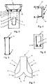
Der Siphon nach den
Unterstützend kann ein den Ventilhebel
Der einen bauchigen Querschnitt aufweisende, tassenförmige Einlauf
Der Verlauf des Rohres
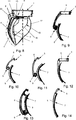
Die
Der Siphon nach den
BezugszeichenlisteLIST OF REFERENCE NUMBERS
- 1 1
- Einlauf enema
- 2 2
- Auslauf outlet
- 3 3
- Auslassöffnung outlet
- 4 4
- Ventil Valve
- 5 5
- Scharniergelenk hinge
- 6 6
- Ventilhebel valve lever
- 7 7
- Ventilfläche valve surface
- 8 8th
- Scharniergelenk hinge
- 9 9
- Ventilklappe valve flap
- 10 10
- Dichtung poetry
- 11 11
- Dichtfläche sealing surface
- 12 12
- Gehäuse casing
- 13 13
- Ausnehmung recess
- 14 14
- Gelenkbolzen hinge pins
- 15 15
- Distanznocken spacer cams
- 16 16
- Klammer clip
- 17 17
- Öffnung opening
- 18 18
- Rohr pipe
- 19 19
- Bogen bow
- 20 20
- Haltestift retaining pin
- 21 21
- Öffnung opening
- 22 22
- Feder feather
ZITATE ENTHALTEN IN DER BESCHREIBUNG QUOTES INCLUDE IN THE DESCRIPTION
Diese Liste der vom Anmelder aufgeführten Dokumente wurde automatisiert erzeugt und ist ausschließlich zur besseren Information des Lesers aufgenommen. Die Liste ist nicht Bestandteil der deutschen Patent- bzw. Gebrauchsmusteranmeldung. Das DPMA übernimmt keinerlei Haftung für etwaige Fehler oder Auslassungen.This list of the documents listed by the applicant has been generated automatically and is included solely for the better information of the reader. The list is not part of the German patent or utility model application. The DPMA assumes no liability for any errors or omissions.
Zitierte PatentliteraturCited patent literature
- EP 1972727 A1 [0002, 0002] EP 1972727 A1 [0002, 0002]
- US 6318397 A [0003] US 6318397 A [0003]
Claims (16)
Priority Applications (9)
| Application Number | Priority Date | Filing Date | Title |
|---|---|---|---|
| DE102012103025A DE102012103025A1 (en) | 2012-04-05 | 2012-04-05 | siphon |
| EP13718095.6A EP2861803B1 (en) | 2012-04-05 | 2013-03-12 | Siphon, particularly an odour trap for a urinal, a floor drain and/or a shower tray or the like |
| PCT/DE2013/100093 WO2013149613A2 (en) | 2012-04-05 | 2013-03-12 | Siphon, particularly an odour trap for a urinal, a floor drain and/or a shower tray or the like |
| CN201380024810.4A CN104285018A (en) | 2012-04-05 | 2013-03-12 | Siphon, particularly an odour trap for a urinal, a floor drain and/or a shower tray or the like |
| AU2013243060A AU2013243060A1 (en) | 2012-04-05 | 2013-03-12 | Siphon, particularly an odour trap for a urinal, a floor drain and/or a shower tray or the like |
| IN9021DEN2014 IN2014DN09021A (en) | 2012-04-05 | 2013-03-12 | |
| US14/390,316 US20150074892A1 (en) | 2012-04-05 | 2013-03-12 | Siphon, particularly an odour trap for a urinal, a floor drain and/or a shower tray or the like |
| MX2014011918A MX2014011918A (en) | 2012-04-05 | 2013-03-12 | Siphon, particularly an odour trap for a urinal, a floor drain and/or a shower tray or the like. |
| JP2015503756A JP2015518532A (en) | 2012-04-05 | 2013-03-12 | Deodorant traps for siphons, especially urinals, floor drains, and / or shower trays |
Applications Claiming Priority (1)
| Application Number | Priority Date | Filing Date | Title |
|---|---|---|---|
| DE102012103025A DE102012103025A1 (en) | 2012-04-05 | 2012-04-05 | siphon |
Publications (1)
| Publication Number | Publication Date |
|---|---|
| DE102012103025A1 true DE102012103025A1 (en) | 2013-10-10 |
Family
ID=48170387
Family Applications (1)
| Application Number | Title | Priority Date | Filing Date |
|---|---|---|---|
| DE102012103025A Ceased DE102012103025A1 (en) | 2012-04-05 | 2012-04-05 | siphon |
Country Status (9)
| Country | Link |
|---|---|
| US (1) | US20150074892A1 (en) |
| EP (1) | EP2861803B1 (en) |
| JP (1) | JP2015518532A (en) |
| CN (1) | CN104285018A (en) |
| AU (1) | AU2013243060A1 (en) |
| DE (1) | DE102012103025A1 (en) |
| IN (1) | IN2014DN09021A (en) |
| MX (1) | MX2014011918A (en) |
| WO (1) | WO2013149613A2 (en) |
Families Citing this family (4)
| Publication number | Priority date | Publication date | Assignee | Title |
|---|---|---|---|---|
| DK179225B1 (en) * | 2015-03-20 | 2018-02-12 | Hedensted Gruppen As | One-way valve. |
| KR101597321B1 (en) * | 2015-06-29 | 2016-02-24 | 주식회사 에코웨이 | Drain Guide Apparatus for Preventing Bad Small and Reverse Flow |
| KR101950886B1 (en) * | 2017-04-11 | 2019-02-21 | 주식회사 디아 | pop-up with check valve |
| US11408160B2 (en) * | 2019-04-09 | 2022-08-09 | Falcon Water Technologies, LLC | Reslient fluid control valve above drainage plane |
Citations (2)
| Publication number | Priority date | Publication date | Assignee | Title |
|---|---|---|---|---|
| US6318397B1 (en) | 1999-08-04 | 2001-11-20 | Donald G. Huber | Side port floor drain |
| EP1972727A1 (en) | 2007-03-19 | 2008-09-24 | Michael C. Untiedt | Waste pipe from urinal |
Family Cites Families (14)
| Publication number | Priority date | Publication date | Assignee | Title |
|---|---|---|---|---|
| US748936A (en) * | 1904-01-05 | Combined floor-drain and backwater-trap | ||
| US2770314A (en) * | 1954-11-03 | 1956-11-13 | Paul R Powell | Floor drain |
| GB915410A (en) * | 1961-04-12 | 1963-01-09 | Jerrold Stuart Newman | Improved drainage structure |
| US5794655A (en) * | 1997-02-25 | 1998-08-18 | Conbraco Industries, Inc. | Swing-type check valve assembly having an integrated valve seat and valve housing cover |
| CN2493657Y (en) * | 2001-05-25 | 2002-05-29 | 潘跃华 | Leakage proof check device |
| US8112827B2 (en) * | 2005-08-02 | 2012-02-14 | Schluter Systems L.P. | Shower drain adapter |
| US20070174960A1 (en) * | 2005-11-25 | 2007-08-02 | Lee Sang-Hwa | Odor control apparatus for drains |
| KR100674890B1 (en) * | 2006-02-04 | 2007-01-29 | 김미화 | Drainage device |
| EP1936047B1 (en) * | 2006-12-18 | 2016-05-18 | Geberit International AG | Drain fitting for a sanitary item |
| DE202008013454U1 (en) * | 2008-10-09 | 2009-03-19 | 1Trade Gmbh | Waterless urinal lock / toilet |
| US20100320130A1 (en) * | 2010-08-24 | 2010-12-23 | Meyers Lawrence G | Floor drain with drain field |
| CN201915489U (en) * | 2011-02-15 | 2011-08-03 | 北京中德博力科技有限公司 | Highly watertight, high-water drainage odor-proof floor drain |
| CN202181586U (en) * | 2011-08-02 | 2012-04-04 | 天津市恒洁久安科技有限公司 | Dirt return prevention connecting pipe |
| CN202644676U (en) * | 2012-06-08 | 2013-01-02 | 天津市恒洁久安科技有限公司 | Sewage-return-proof tube core |
-
2012
- 2012-04-05 DE DE102012103025A patent/DE102012103025A1/en not_active Ceased
-
2013
- 2013-03-12 WO PCT/DE2013/100093 patent/WO2013149613A2/en active Application Filing
- 2013-03-12 CN CN201380024810.4A patent/CN104285018A/en active Pending
- 2013-03-12 JP JP2015503756A patent/JP2015518532A/en active Pending
- 2013-03-12 IN IN9021DEN2014 patent/IN2014DN09021A/en unknown
- 2013-03-12 US US14/390,316 patent/US20150074892A1/en not_active Abandoned
- 2013-03-12 EP EP13718095.6A patent/EP2861803B1/en active Active
- 2013-03-12 MX MX2014011918A patent/MX2014011918A/en unknown
- 2013-03-12 AU AU2013243060A patent/AU2013243060A1/en not_active Abandoned
Patent Citations (2)
| Publication number | Priority date | Publication date | Assignee | Title |
|---|---|---|---|---|
| US6318397B1 (en) | 1999-08-04 | 2001-11-20 | Donald G. Huber | Side port floor drain |
| EP1972727A1 (en) | 2007-03-19 | 2008-09-24 | Michael C. Untiedt | Waste pipe from urinal |
Also Published As
| Publication number | Publication date |
|---|---|
| IN2014DN09021A (en) | 2015-05-22 |
| AU2013243060A1 (en) | 2014-11-20 |
| CN104285018A (en) | 2015-01-14 |
| US20150074892A1 (en) | 2015-03-19 |
| EP2861803A2 (en) | 2015-04-22 |
| EP2861803B1 (en) | 2021-12-22 |
| WO2013149613A2 (en) | 2013-10-10 |
| MX2014011918A (en) | 2015-05-11 |
| WO2013149613A3 (en) | 2013-11-28 |
| JP2015518532A (en) | 2015-07-02 |
Similar Documents
| Publication | Publication Date | Title |
|---|---|---|
| EP1972727B1 (en) | Waste pipe from urinal | |
| DE102012103025A1 (en) | siphon | |
| DE2753929A1 (en) | WATER SAVING VALVE DEVICE FOR THE FLUSHBOX OF WATER TOOLS | |
| WO2018104411A2 (en) | Pressure-flushing system for a toilet bowl | |
| EP1588083B1 (en) | Backflow preventer | |
| EP2363542B1 (en) | Control assembly | |
| EP2706157B1 (en) | Check-valve for a vacuum waste water system | |
| DE102017130585A1 (en) | Drain valve for a sanitary cistern | |
| DE102005029520B4 (en) | Shut-off device for a sewer control shaft | |
| DE102011106240B4 (en) | Odor trap for urinals without flushing water connection | |
| DE102008021758B3 (en) | Container for flush rinsing of channel with flowing medium, has rinsing cover which is pivoted between stored position and raised position inside channel around axle | |
| EP1900987B1 (en) | Shut-off valve with upper part flushing | |
| EP0986679A1 (en) | Toilet system with vacuum suction | |
| EP2785926B1 (en) | Back pressure safeguard | |
| AT17914U1 (en) | Mission | |
| AT523236B1 (en) | Drainage device | |
| EP1995503B1 (en) | Valve seal assembly | |
| DE202015105874U1 (en) | Hydraulically actuated flushing valve | |
| DE102012207200B4 (en) | Fire hydrant with stone trap | |
| DE102014114902A1 (en) | Shut-off and flow control tap | |
| DE202007019422U1 (en) | Waterless sanitary facility and siphon for such a system | |
| EP2177680A1 (en) | Non-return valve | |
| DE102016011796A1 (en) | Device for odor-tight closing of a drain line | |
| DE102007002353B4 (en) | Closure device for a vacuum consumer system of an aircraft | |
| DE102012205304A1 (en) | Back-flow preventer for arrangement in waste water pipe that is utilized for discharging household waste water into drainage ditch, has surface segments for covering opening, where edges of segments tilt against each other |
Legal Events
| Date | Code | Title | Description |
|---|---|---|---|
| R012 | Request for examination validly filed | ||
| R016 | Response to examination communication | ||
| R002 | Refusal decision in examination/registration proceedings | ||
| R003 | Refusal decision now final |