DE102012102788A1 - BARRIER TEMPERATURE MEASUREMENT OF A POWER MOSFET - Google Patents
BARRIER TEMPERATURE MEASUREMENT OF A POWER MOSFET Download PDFInfo
- Publication number
- DE102012102788A1 DE102012102788A1 DE102012102788A DE102012102788A DE102012102788A1 DE 102012102788 A1 DE102012102788 A1 DE 102012102788A1 DE 102012102788 A DE102012102788 A DE 102012102788A DE 102012102788 A DE102012102788 A DE 102012102788A DE 102012102788 A1 DE102012102788 A1 DE 102012102788A1
- Authority
- DE
- Germany
- Prior art keywords
- diode
- mosfet
- component
- measuring
- junction temperature
- Prior art date
- Legal status (The legal status is an assumption and is not a legal conclusion. Google has not performed a legal analysis and makes no representation as to the accuracy of the status listed.)
- Ceased
Links
Images


Classifications
-
- H—ELECTRICITY
- H01—ELECTRIC ELEMENTS
- H01L—SEMICONDUCTOR DEVICES NOT COVERED BY CLASS H10
- H01L23/00—Details of semiconductor or other solid state devices
- H01L23/34—Arrangements for cooling, heating, ventilating or temperature compensation ; Temperature sensing arrangements
-
- H—ELECTRICITY
- H02—GENERATION; CONVERSION OR DISTRIBUTION OF ELECTRIC POWER
- H02P—CONTROL OR REGULATION OF ELECTRIC MOTORS, ELECTRIC GENERATORS OR DYNAMO-ELECTRIC CONVERTERS; CONTROLLING TRANSFORMERS, REACTORS OR CHOKE COILS
- H02P29/00—Arrangements for regulating or controlling electric motors, appropriate for both AC and DC motors
- H02P29/60—Controlling or determining the temperature of the motor or of the drive
- H02P29/68—Controlling or determining the temperature of the motor or of the drive based on the temperature of a drive component or a semiconductor component
-
- H—ELECTRICITY
- H01—ELECTRIC ELEMENTS
- H01L—SEMICONDUCTOR DEVICES NOT COVERED BY CLASS H10
- H01L2924/00—Indexing scheme for arrangements or methods for connecting or disconnecting semiconductor or solid-state bodies as covered by H01L24/00
- H01L2924/0001—Technical content checked by a classifier
- H01L2924/0002—Not covered by any one of groups H01L24/00, H01L24/00 and H01L2224/00
-
- H—ELECTRICITY
- H02—GENERATION; CONVERSION OR DISTRIBUTION OF ELECTRIC POWER
- H02P—CONTROL OR REGULATION OF ELECTRIC MOTORS, ELECTRIC GENERATORS OR DYNAMO-ELECTRIC CONVERTERS; CONTROLLING TRANSFORMERS, REACTORS OR CHOKE COILS
- H02P27/00—Arrangements or methods for the control of AC motors characterised by the kind of supply voltage
- H02P27/04—Arrangements or methods for the control of AC motors characterised by the kind of supply voltage using variable-frequency supply voltage, e.g. inverter or converter supply voltage
- H02P27/06—Arrangements or methods for the control of AC motors characterised by the kind of supply voltage using variable-frequency supply voltage, e.g. inverter or converter supply voltage using dc to ac converters or inverters
Landscapes
- Engineering & Computer Science (AREA)
- Power Engineering (AREA)
- Physics & Mathematics (AREA)
- Condensed Matter Physics & Semiconductors (AREA)
- General Physics & Mathematics (AREA)
- Computer Hardware Design (AREA)
- Microelectronics & Electronic Packaging (AREA)
- Power Steering Mechanism (AREA)
- Inverter Devices (AREA)
Abstract
Es wird ein Bauteil als Leistungsschalter für einen Wechselrichter zur Ansteuerung eines Antriebsmotors einer Lenkunterstützung eines Fahrzeugs beschrieben, umfassend: einen Mosfet 2 mit einem Gate, einem Drain und einer Source und eine erste Diode 4 mit einer Anode und einer Kathode, wobei die Diode 4 zur Messung der Sperrschichttemperatur des Mosfets 2 vorgesehen ist, wobei der Mosfet 2 vom N-Kanal-Typ oder P-Kanal-Typ ist und die Source mit der Kathode verbunden ist.A component is described as a power switch for an inverter for driving a drive motor of a steering assistance of a vehicle, comprising: a mosfet 2 with a gate, a drain and a source and a first diode 4 with an anode and a cathode, wherein the diode 4 to Measurement of the junction temperature of the MOSFET 2 is provided, wherein the mosfet 2 of the N-channel type or P-channel type and the source is connected to the cathode.
Description
GEBIET DER ERFINDUNG FIELD OF THE INVENTION
Die vorliegende Erfindung betrifft ein Bauteil als Leistungsschalter für einen Wechselrichter zur Ansteuerung eines Antriebsmotors einer Lenkunterstützung eines Fahrzeugs, eine Servolenkung für ein Kraftfahrzeug und ein Lenksystem. The present invention relates to a component as a power switch for an inverter for controlling a drive motor of a steering assistance of a vehicle, a power steering system for a motor vehicle and a steering system.
HINTERGRUND DER ERFINDUNG BACKGROUND OF THE INVENTION
Im Stand der Technik sind Bauteile bekannt, die einen Mosfet aufweisen sowie eine Diode zur Messung der Sperrschichttemperatur des Mosfets. Die Diode weist dabei einen Anodenanschluss und einen Kathodenanschluss auf, die aus dem Bauteil herausführend ausgebildet sind. In the prior art components are known which have a Mosfet and a diode for measuring the junction temperature of the Mosfet. In this case, the diode has an anode connection and a cathode connection, which are designed to lead out of the component.
ZUSAMMENFASSUNG DER ERFINDUNG SUMMARY OF THE INVENTION
Bauteile des Stands der Technik, die eine Messung der Sperrschichttemperatur des Mosfets ermöglichen, weisen zumindest zwei Anschlüsse einer zusätzlichen Sensordiode auf. Die zwei zusätzlichen Anschlüsse erfordern eine zusätzliche Beschaltung, was zu einem erhöhten Aufwand bei der Herstellung und einem erhöhten Raumbedarf der Schaltung und der Die-Fläche (Chipfläche) des Mosfets führt. Prior art devices that enable measurement of the junction temperature of the mosfet include at least two terminals of an additional sensor diode. The two additional connections require additional wiring, which leads to an increased expenditure in the production and an increased space requirement of the circuit and the die area (chip area) of the MOSFET.
Eine Aufgabe ist daher ein Bauteil mit einem Mosfet zur Verfügung zu stellen, das eine Messung der Sperrschichttemperatur des Mosfets ermöglicht, wobei möglichst wenige zusätzliche Anschlüsse notwendig sind bzw. die zusätzliche Beschaltung gering gehalten werden kann bzw. der Raumbedarf der Schaltung und der Die-Fläche nicht signifikant vergrößert bzw. verändert werden muss. It is therefore an object to provide a component with a mosfet which makes it possible to measure the junction temperature of the mosfet, with as few additional connections as possible or the additional circuitry being able to be kept low or the space requirement of the circuit and the die surface does not have to be significantly increased or changed.
Als erste Ausführungsform der Erfindung wird ein Bauteil als Leistungsschalter für einen Wechselrichter zur Ansteuerung eines Antriebsmotors einer Lenkunterstützung eines Fahrzeugs zur Verfügung gestellt, umfassend: einen Mosfet mit einem Gate, einem Drain und einer Source und eine erste Diode mit einer Anode und einer Kathode, wobei die Diode zur Messung der Sperrschichttemperatur des Mosfets vorgesehen ist, wobei der Mosfet vom N-Kanal-Typ oder P-Kanal-Typ ist und die Source mit der Kathode verbunden ist. As a first embodiment of the invention, there is provided a component as a power switch for an inverter for driving a drive motor of a steering assist of a vehicle, comprising: a MOSFET having a gate, a drain and a source and a first diode having an anode and a cathode, wherein the diode is provided for measuring the junction temperature of the MOSFET, wherein the MOSFET is of the N-channel type or P-channel type and the source is connected to the cathode.
Vorteilhafterweise kann durch das erfindungsgemäße Bauteil eine optimale Ausnutzung der thermischen Fähigkeiten des Bauteils erfolgen, und zwar dadurch, dass dank dem erfindungsgemäßen Bauteil eine Leistungsreduzierung der Lenkunterstützung vorgenommen werden kann, falls durch das Bauteil eine obere Grenztemperatur des Mosfets festgestellt wird. Hierdurch kann das komplette Potential des betreffenden Mosfets des Wechselrichters ausgeschöpft werden. Advantageously, can be carried out by the inventive component optimum utilization of the thermal capabilities of the component, namely the fact that thanks to the component according to the invention, a power reduction of the steering assistance can be made if an upper limit temperature of the Mosfets is determined by the component. As a result, the entire potential of the respective Mosfets of the inverter can be exhausted.
Erfindungsgemäß wird die Source des Mosfets und die Kathode der Diode miteinander verbunden, wodurch die Anzahl der aus dem Chip herauszuführenden Anschlüsse reduziert werden kann. According to the invention, the source of the MOSFET and the cathode of the diode are connected to each other, whereby the number of leads to be led out of the chip can be reduced.
Als zweite Ausführungsform der Erfindung wird eine Servolenkung für ein Kraftfahrzeug zur Verfügung gestellt, umfassend: einen Antriebsmotor zum Erzeugen eines Antriebsmoments auf eine Zahnstange eines Lenksystems und einen Wechselrichter zur Ansteuerung des Antriebsmotors, wobei der Wechselrichter ein Bauteil und/oder sechs Bauteile nach einem der Ansprüche 1 bis 4 umfasst. As a second embodiment of the invention, a power steering system for a motor vehicle is provided, comprising: a drive motor for generating a drive torque on a rack of a steering system and an inverter for driving the drive motor, wherein the inverter comprises a component and / or six components according to one of the
Durch den Einsatz mindestens eines erfindungsgemäßen Bauteils kann eine Servolenkung bereitgestellt werden, die eine weniger aufwändige externe Beschaltung notwendig macht und daher im Vergleich zu Servolenkungen des Stands der Technik einen kleineren Bauraum benötigt. By using at least one component according to the invention, a power steering can be provided which makes a less complicated external wiring necessary and therefore requires a smaller space compared to power steering systems of the prior art.
Als dritte Ausführungsform der Erfindung wird ein Lenksystem umfassend eine Servolenkung nach Anspruch 5 zur Verfügung gestellt. As a third embodiment of the invention, a steering system comprising a power steering system according to
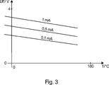
Als vierte Ausführungsform der Erfindung wird ein Verfahren zur Messung der Sperrschichttemperatur eines Mosfets eines Bauteils nach den Ansprüchen 1 bis 4 zur Verfügung gestellt, umfassend die Schritte: Einspeisen eines konstanten Vorwärtsstrom IF in die Diode und Messen der Vorwärtsspannung VF der Diode. As a fourth embodiment of the invention, there is provided a method of measuring the junction temperature of a device MOSFET according to
Als fünfte Ausführungsform der Erfindung wird ein Verfahren zur Messung der Sperrschichttemperatur eines Mosfets eines Bauteils nach den Ansprüchen 1 bis 4 zur Verfügung gestellt, umfassend die Schritte: Konstanthalten der Vorwärtsspannung VF der Diode und Messen des Vorwärtsstroms IF der Diode. As a fifth embodiment of the invention, there is provided a method of measuring the junction temperature of a MOSFET of a device according to
Bei einem erfindungsgemäßen Bauteil kann die Sensordiode/Diode grundsätzlich auf zwei verschiedene Weisen beschaltet werden, um die Sperrschichttemperatur des entsprechenden Mosfets bestimmen zu können. Zum einen kann in die Diode in Durchlassrichtung ein konstanter Strom eingespeist werden und die temperaturabhängige Spannung der Diode gemessen werden. Zum anderen kann die Durchlassspannung der Diode konstant gehalten werden und der Diodenstrom gemessen werden und daraus die Sperrschichttemperatur bestimmt werden. In the case of a component according to the invention, the sensor diode / diode can basically be connected in two different ways in order to be able to determine the junction temperature of the corresponding MOSFET. On the one hand, a constant current can be fed into the diode in the forward direction and the temperature-dependent voltage of the diode can be measured. On the other hand, the forward voltage of the diode can be kept constant and the diode current can be measured and from this the junction temperature can be determined.
Beispielhafte Ausführungsformen werden in den abhängigen Ansprüchen beschrieben. Exemplary embodiments are described in the dependent claims.
Gemäß einer beispielhaften Ausführungsform der Erfindung wird ein Bauteil zur Verfügung gestellt, wobei die erste Diode und der Mosfet auf demselben Halbleitersubtrat angeordnet sind. According to an exemplary embodiment of the invention, a device is provided, wherein the first diode and the mosfet are disposed on the same semiconductor substrate.
Durch die Anordnung der Diode und des Mosfets auf demselben Halbleitersubstrat wird ein sehr guter thermischer Kontakt der Diode mit der Sperrschicht des Mosfets erzielt. Somit kann eine direkte Temperaturmessung vorgenommen werden, wodurch sich präzise Angaben über die Sperrschichttemperatur ergeben. By arranging the diode and the MOSFET on the same semiconductor substrate, a very good thermal contact of the diode with the barrier layer of the MOSFET is achieved. Thus, a direct temperature measurement can be made, resulting in precise information about the junction temperature.
In einer weiteren erfindungsgemäßen Ausführungsform wird ein Bauteil zur Verfügung gestellt, wobei die erste Diode als Si-Diode, Suppressordiode, Schottkydiode, PIN-Diode oder als Zenerdiode ausgebildet ist. In a further embodiment of the invention, a component is provided, wherein the first diode is designed as a Si diode, suppressor diode, Schottky diode, PIN diode or Zener diode.
Durch die Verwendung von Standardtypen von Dioden, beispielsweise eine Si-Diode, eine Suppressordiode, eine Schottkydiode, eine PIN-Diode oder eine Zenerdiode, kann ein kostengünstiger Aufbau eines erfindungsgemäßen Bauteils erreicht werden. By using standard types of diodes, for example a Si diode, a suppressor diode, a Schottky diode, a PIN diode or a Zener diode, a cost-effective design of a component according to the invention can be achieved.
Gemäß einem weiteren Ausführungsbeispiel der vorliegenden Erfindung wird ein Bauteil zur Verfügung gestellt, wobei das Bauteil eine zweite Diode und/oder eine dritte Diode und/oder eine vierte Diode und/oder beliebig viele weitere Dioden umfasst, wobei die erste Diode und/oder die zweite Diode und/oder die dritte Diode und/oder die vierte Diode und/oder beliebig viele Dioden in Reihe geschaltet sind und/oder thermisch mit der Sperrschicht des Mosfets gekoppelt sind. According to a further embodiment of the present invention, a component is provided, wherein the component comprises a second diode and / or a third diode and / or a fourth diode and / or any number of further diodes, wherein the first diode and / or the second Diode and / or the third diode and / or the fourth diode and / or any number of diodes are connected in series and / or thermally coupled to the barrier layer of Mosfets.
Durch eine Verwendung von mehreren Dioden, die in Reihe geschaltet sind, kann die Temperatur der Sperrschicht genauer gemessen werden, da hierdurch das Phänomen der Temperaturabhängigkeit der entsprechenden Vorwärtsspannungen mehrfach genutzt werden kann. By using a plurality of diodes in series, the temperature of the barrier layer can be more accurately measured, since it can multiply utilize the phenomenon of temperature dependency of the respective forward voltages.
Als eine Idee der Erfindung kann angesehen werden, ein Bauteil mit einem Mosfet zur Verfügung zu stellen, das on-board eine Diode zur Messung der Sperrschichttemperatur aufweist. Die Kathode der Diode ist hierbei intern mit der Source des Mosfets verbunden, wodurch die Anzahl der herausgeführten Anschlüsse verringert werden kann. Hierdurch kann nicht nur eine genaue Messung der Sperrschichttemperatur vorgenommen werden, sondern auch eine kleine Chipfläche des Bauteils erreicht werden. As an idea of the invention, it can be considered to provide a component having a mosfet having on-board a diode for measuring the junction temperature. The cathode of the diode is internally connected to the source of the mosfet, whereby the number of lead-out terminals can be reduced. As a result, not only an accurate measurement of the junction temperature can be made, but also a small chip area of the component can be achieved.
Die einzelnen Merkmale können selbstverständlich auch untereinander kombiniert werden, wodurch sich zum Teil auch vorteilhafte Wirkungen einstellen können, die über die Summe der Einzelwirkungen hinausgehen. Of course, the individual features can also be combined with each other, which can also be partially beneficial effects that go beyond the sum of the individual effects.
KURZE BESCHREIBUNG DER ZEICHNUNGEN BRIEF DESCRIPTION OF THE DRAWINGS
Weitere Einzelheiten und Vorteile der Erfindung werden anhand der in den Zeichnungen dargestellten Ausführungsbeispiele deutlich. Es zeigen Further details and advantages of the invention will become apparent from the embodiments illustrated in the drawings. Show it
DETAILLIERTE BESCHREIBUNG BEISPIELHAFTER AUSFÜHRUNGSFORMEN DETAILED DESCRIPTION OF EXEMPLARY EMBODIMENTS
Die so ermittelten Temperaturinformationen können z.B. dafür verwendet werden, die Mosfets vor einer thermischen Überlastung zu schützen. Wird beispielsweise eine kritische Sperrschichttemperatur erreicht, wird die Lenkunterstützung für das Fahrzeug reduziert und somit die Verlustleistung, die in den Wechselrichter-Mosfets entsteht, verringert. Als weitere Anwendungsmöglichkeit könnte aus den direkt gemessenen Mosfets-Sperrschichttemperaturen ein Temperaturstrommodell abgeleitet werden, mit dem die aktuellen Motorphasenströme geschätzt werden können. Dies hat den Vorteil, dass die Sensoren für die Phasenstrommessung entfallen können. The temperature information thus obtained may e.g. used to protect the mosfets from thermal overload. If, for example, a critical junction temperature is reached, the steering assistance to the vehicle is reduced, thus reducing the power loss resulting in the inverter mosfets. As a further possible application, it would be possible to derive a temperature current model from the directly measured Mosfets junction temperatures, with which the current motor phase currents can be estimated. This has the advantage that the sensors for the phase current measurement can be omitted.
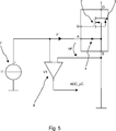
Die Hilfsbeschaltung zum Einprägen des Konstantstroms IF, also insbesondere die Konstantstromquelle
Der Vorteil der Mosfet-Temperaturmessung ergibt sich aus der Genauigkeit der Temperaturmesswerte, die sich direkt auf die Sperrschichttemperatur des Mosfets beziehen. Es werden somit keine komplexen thermischen Modelle mehr benötigt, bei denen z.B. aus einer NTC-Sensortemperatur die Mosfet-Temperatur abgeleitet werden muss. Somit kann ein derartiger NTC-Sensor zur Bestimmung der Endstufentemperatur entfallen und Kosten eingespart werden. The advantage of Mosfet temperature measurement results from the accuracy of temperature readings directly related to the junction temperature of the mosfet. Thus, complex thermal models are no longer needed in which e.g. from an NTC sensor temperature the Mosfet temperature must be derived. Thus, such an NTC sensor for determining the final stage temperature can be omitted and costs can be saved.
Als weitere Variante wäre es denkbar, dass die Spannung VF konstant gehalten wird und der Strom IF in Abhängigkeit der Sperrschichttemperatur gemessen wird. Bei dieser Variante muss allerdings berücksichtigt werden, dass der Vorwärtsstrom IF sehr klein ist. Ein derart erhaltener Strom IF könnte mit Hilfe eines Stromspiegels verstärkt werden und als Spannung an einem Messshunt abgegriffen werden. Der Spannungsabfall am Messshunt entspräche dann der Sperrschichttemperatur des Leistungs-Mosfets. As a further variant, it would be conceivable that the voltage V F is kept constant and the current I F is measured as a function of the junction temperature. In this variant, however, it must be taken into account that the forward current I F is very small. A current I F obtained in this way could be amplified by means of a current mirror and tapped as a voltage across a measuring shunt. The voltage drop at the measuring shunt would then correspond to the junction temperature of the power MOSFET.
Es sei angemerkt, dass der Begriff „umfassen“ weitere Elemente oder Verfahrensschritte nicht ausschließt, ebenso wie der Begriff „ein“ und „eine“ mehrere Elemente und Schritte nicht ausschließt. It should be noted that the term "comprising" does not exclude other elements or method steps, just as the term "a" and "an" does not exclude multiple elements and steps.
Die verwendeten Bezugszeichen dienen lediglich zur Erhöhung der Verständlichkeit und sollen keinesfalls als einschränkend betrachtet werden, wobei der Schutzbereich der Erfindung durch die Ansprüche wiedergegeben wird. The reference numerals used are for convenience of reference only and are not to be considered as limiting, the scope of the invention being indicated by the claims.
BezugszeichenlisteLIST OF REFERENCE NUMBERS
- 1 1
- Bauteil component
- 2 2
- Mosfet Mosfet
- 3 3
- Freilaufdiode Freewheeling diode
- 4 4
- Diode diode
- 5 5
- Mosfet Mosfet
- 6 6
- Diode diode
- 7 7
- Konstantstromquelle Constant current source
- 8 8th
- Verstärkerschaltung amplifier circuit
- 9 9
- Antriebsmotor einer Servoschaltung Drive motor of a servo circuit
- 10 10
- Sourceanschluss source terminal
- 11 11
- Drainanschluss drain
- 12 12
- Sourceanschluss source terminal
- 13 13
- Gateanschluss gate terminal
- 14 14
- Anodenanschluss anode
- 15 15
- Anodenanschluss anode
Claims (8)
Priority Applications (4)
| Application Number | Priority Date | Filing Date | Title |
|---|---|---|---|
| DE102012102788A DE102012102788A1 (en) | 2012-03-30 | 2012-03-30 | BARRIER TEMPERATURE MEASUREMENT OF A POWER MOSFET |
| US13/772,869 US20130257329A1 (en) | 2012-03-30 | 2013-02-21 | Junction temperature measurement of a power mosfet |
| JP2013062480A JP2013213819A (en) | 2012-03-30 | 2013-03-25 | Junction temperature measurement of power mosfet |
| CN2013101007412A CN103368412A (en) | 2012-03-30 | 2013-03-27 | Junction temperature measurement of a power MOSFET |
Applications Claiming Priority (1)
| Application Number | Priority Date | Filing Date | Title |
|---|---|---|---|
| DE102012102788A DE102012102788A1 (en) | 2012-03-30 | 2012-03-30 | BARRIER TEMPERATURE MEASUREMENT OF A POWER MOSFET |
Publications (1)
| Publication Number | Publication Date |
|---|---|
| DE102012102788A1 true DE102012102788A1 (en) | 2013-10-02 |
Family
ID=49154588
Family Applications (1)
| Application Number | Title | Priority Date | Filing Date |
|---|---|---|---|
| DE102012102788A Ceased DE102012102788A1 (en) | 2012-03-30 | 2012-03-30 | BARRIER TEMPERATURE MEASUREMENT OF A POWER MOSFET |
Country Status (4)
| Country | Link |
|---|---|
| US (1) | US20130257329A1 (en) |
| JP (1) | JP2013213819A (en) |
| CN (1) | CN103368412A (en) |
| DE (1) | DE102012102788A1 (en) |
Cited By (2)
| Publication number | Priority date | Publication date | Assignee | Title |
|---|---|---|---|---|
| DE102014100122B3 (en) * | 2014-01-08 | 2015-04-16 | Zf Lenksysteme Gmbh | Determination of the junction temperature of a fet by the body diode |
| WO2020064485A1 (en) | 2018-09-27 | 2020-04-02 | Thyssenkrupp Presta Ag | Temperature measurement of a power semiconductor switching element |
Families Citing this family (7)
| Publication number | Priority date | Publication date | Assignee | Title |
|---|---|---|---|---|
| US20150346037A1 (en) * | 2014-05-29 | 2015-12-03 | Infineon Technologies Ag | Integrated temperature sensor |
| US10132696B2 (en) | 2014-07-11 | 2018-11-20 | Infineon Technologies Ag | Integrated temperature sensor for discrete semiconductor devices |
| ITUB20150366A1 (en) | 2015-04-23 | 2016-10-23 | St Microelectronics Srl | INTEGRATED ELECTRONIC DEVICE INCLUDING A TEMPERATURE TRANSDUCER |
| US9608558B1 (en) * | 2015-09-14 | 2017-03-28 | Infineon Technologies Ag | Calculation of MOSFET switch temperature in motor control |
| DE102015223470A1 (en) * | 2015-11-26 | 2017-06-01 | Robert Bosch Gmbh | Semiconductor device having a substrate and a first temperature measuring element and method for determining a current flowing through a semiconductor device and current control device for a vehicle |
| WO2019023028A1 (en) * | 2017-07-24 | 2019-01-31 | Macom Technology Solutions Holdings, Inc. | Fet operational temperature determination by resistance thermometry |
| KR20210032111A (en) | 2019-09-16 | 2021-03-24 | 삼성전자주식회사 | Semiconductor memory device and memory system having the same |
Citations (4)
| Publication number | Priority date | Publication date | Assignee | Title |
|---|---|---|---|---|
| US4963970A (en) * | 1987-11-06 | 1990-10-16 | Nissan Motor Company, Limited | Vertical MOSFET device having protector |
| DE19652046A1 (en) * | 1996-12-13 | 1998-06-18 | Siemens Ag | Temperature measuring method of semiconductor chip |
| US20090066404A1 (en) * | 2005-03-15 | 2009-03-12 | Nxp B.V. | Mosfet with temperature sense facility |
| DE102011050122A1 (en) * | 2010-12-17 | 2012-06-21 | Zf Lenksysteme Gmbh | Component useful as a circuit breaker for an inverter, comprises a MOSFET having a gate terminal and a source terminal, a first diode for measuring a junction temperature of the MOSFET, and a second diode and/or a third diode |
Family Cites Families (5)
| Publication number | Priority date | Publication date | Assignee | Title |
|---|---|---|---|---|
| DE69325645T2 (en) * | 1993-04-21 | 1999-12-09 | Cons Ric Microelettronica | Integrated protection circuit structure for the protection of logic MOS power semiconductor components from electrostatic discharges |
| JP4917709B2 (en) * | 2000-03-06 | 2012-04-18 | ローム株式会社 | Semiconductor device |
| JP2010100217A (en) * | 2008-10-24 | 2010-05-06 | Jtekt Corp | Electric power-steering device |
| CN201821077U (en) * | 2010-09-21 | 2011-05-04 | 上海航天汽车机电股份有限公司 | Overcurrent protection circuit |
| DE102012200089A1 (en) * | 2011-01-07 | 2012-07-12 | Honda Motor Co., Ltd. | Electric power steering device |
-
2012
- 2012-03-30 DE DE102012102788A patent/DE102012102788A1/en not_active Ceased
-
2013
- 2013-02-21 US US13/772,869 patent/US20130257329A1/en not_active Abandoned
- 2013-03-25 JP JP2013062480A patent/JP2013213819A/en active Pending
- 2013-03-27 CN CN2013101007412A patent/CN103368412A/en active Pending
Patent Citations (4)
| Publication number | Priority date | Publication date | Assignee | Title |
|---|---|---|---|---|
| US4963970A (en) * | 1987-11-06 | 1990-10-16 | Nissan Motor Company, Limited | Vertical MOSFET device having protector |
| DE19652046A1 (en) * | 1996-12-13 | 1998-06-18 | Siemens Ag | Temperature measuring method of semiconductor chip |
| US20090066404A1 (en) * | 2005-03-15 | 2009-03-12 | Nxp B.V. | Mosfet with temperature sense facility |
| DE102011050122A1 (en) * | 2010-12-17 | 2012-06-21 | Zf Lenksysteme Gmbh | Component useful as a circuit breaker for an inverter, comprises a MOSFET having a gate terminal and a source terminal, a first diode for measuring a junction temperature of the MOSFET, and a second diode and/or a third diode |
Cited By (3)
| Publication number | Priority date | Publication date | Assignee | Title |
|---|---|---|---|---|
| DE102014100122B3 (en) * | 2014-01-08 | 2015-04-16 | Zf Lenksysteme Gmbh | Determination of the junction temperature of a fet by the body diode |
| WO2020064485A1 (en) | 2018-09-27 | 2020-04-02 | Thyssenkrupp Presta Ag | Temperature measurement of a power semiconductor switching element |
| DE102018123903A1 (en) * | 2018-09-27 | 2020-04-02 | Thyssenkrupp Ag | Temperature measurement of a semiconductor power switching element |
Also Published As
| Publication number | Publication date |
|---|---|
| JP2013213819A (en) | 2013-10-17 |
| US20130257329A1 (en) | 2013-10-03 |
| CN103368412A (en) | 2013-10-23 |
Similar Documents
| Publication | Publication Date | Title |
|---|---|---|
| DE102012102788A1 (en) | BARRIER TEMPERATURE MEASUREMENT OF A POWER MOSFET | |
| DE102010000875B4 (en) | Method for measuring the junction temperature of power semiconductors in a power converter | |
| DE102008045722B4 (en) | Temperature Acquisition System | |
| DE102011050122A1 (en) | Component useful as a circuit breaker for an inverter, comprises a MOSFET having a gate terminal and a source terminal, a first diode for measuring a junction temperature of the MOSFET, and a second diode and/or a third diode | |
| DE112009000503T5 (en) | Linear sensor with two connections | |
| DE102015108410A1 (en) | CURRENT OR VOLTAGE MEASUREMENT | |
| DE102010029147A1 (en) | Method for determining the temperature of a power semiconductor | |
| EP3608644B1 (en) | Method of determining a sign of a load current in a bridge circuit with at least one power semiconductor circuit | |
| DE102015108412A1 (en) | Integrated temperature sensor | |
| DE4236334A1 (en) | Monolithically integrated MOS power amplifier component with an overload protection device | |
| DE102014100122B3 (en) | Determination of the junction temperature of a fet by the body diode | |
| DE102013105439B4 (en) | FLOATING CONNECTION OF A DIODE FOR BARRIER TEMPERATURE MEASUREMENT | |
| DE102014005481B4 (en) | Detection of defective electrical connections | |
| DE102009039966B4 (en) | Power transistor and method of controlling a power transistor | |
| DE102015110102A1 (en) | Current measurement in a power semiconductor arrangement | |
| WO2016139263A1 (en) | Method and device for determining a load current | |
| WO2017089018A1 (en) | Semiconductor component comprising a first temperature measuring element and method for determining a current flowing through a semiconductor component | |
| DE102011001185A1 (en) | Circuit for determining phase current of serially connected circuit breakers for controlling drive motor of power steering system, determines phase of voltage and current based on resistance value of junction temperature | |
| DE102010021171A1 (en) | Device for determining service life of electronic structure e.g. electrical converter, has computing unit computing service life of electronic structure from determined temperature and electrical size of electronic structure | |
| WO2015055483A1 (en) | Method for measuring a temperature | |
| DE102007017584A1 (en) | Signal amplifying circuit for e.g. automobile, has two limiting devices, of which one device removes dropping current from output terminal of amplifying circuit, when output voltage of amplifying circuit exceeds one of reference voltages | |
| DE102015226628A1 (en) | Device and method for current monitoring of a plurality of semiconductor switches | |
| WO2020064485A1 (en) | Temperature measurement of a power semiconductor switching element | |
| EP1324054B1 (en) | Device for measuring the intensity of a magnetic field, magnetic field sensor and current intensity measuring instrument | |
| DE102021130006B3 (en) | METHOD OF DETERMINING AN ON RESISTANCE OF A FIELD EFFECT TRANSISTOR, MODULE FOR CURRENT DETECTION WITH A FIELD EFFECT TRANSISTOR AND ELECTRONIC FUSE WITH THE MODULE |
Legal Events
| Date | Code | Title | Description |
|---|---|---|---|
| R163 | Identified publications notified | ||
| R012 | Request for examination validly filed | ||
| R081 | Change of applicant/patentee |
Owner name: ROBERT BOSCH AUTOMOTIVE STEERING GMBH, DE Free format text: FORMER OWNER: ZF LENKSYSTEME GMBH, 73527 SCHWAEBISCH GMUEND, DE Effective date: 20150423 |
|
| R016 | Response to examination communication | ||
| R002 | Refusal decision in examination/registration proceedings | ||
| R003 | Refusal decision now final |