DE102012024944B4 - diaphragm valve - Google Patents
diaphragm valve Download PDFInfo
- Publication number
- DE102012024944B4 DE102012024944B4 DE102012024944.6A DE102012024944A DE102012024944B4 DE 102012024944 B4 DE102012024944 B4 DE 102012024944B4 DE 102012024944 A DE102012024944 A DE 102012024944A DE 102012024944 B4 DE102012024944 B4 DE 102012024944B4
- Authority
- DE
- Germany
- Prior art keywords
- valve
- pilot
- valve body
- diaphragm
- membrane
- Prior art date
- Legal status (The legal status is an assumption and is not a legal conclusion. Google has not performed a legal analysis and makes no representation as to the accuracy of the status listed.)
- Active
Links
- 239000012528 membrane Substances 0.000 claims abstract description 28
- 238000007789 sealing Methods 0.000 claims abstract description 13
- 239000007788 liquid Substances 0.000 claims abstract description 4
- 230000002093 peripheral effect Effects 0.000 claims description 3
- 238000004519 manufacturing process Methods 0.000 description 2
- 230000000087 stabilizing effect Effects 0.000 description 2
- 230000004913 activation Effects 0.000 description 1
- 230000001934 delay Effects 0.000 description 1
- 230000003111 delayed effect Effects 0.000 description 1
- 238000011161 development Methods 0.000 description 1
- 230000018109 developmental process Effects 0.000 description 1
- 230000000694 effects Effects 0.000 description 1
- 238000005265 energy consumption Methods 0.000 description 1
- 230000004941 influx Effects 0.000 description 1
- 230000007257 malfunction Effects 0.000 description 1
Images

Classifications
-
- F—MECHANICAL ENGINEERING; LIGHTING; HEATING; WEAPONS; BLASTING
- F16—ENGINEERING ELEMENTS AND UNITS; GENERAL MEASURES FOR PRODUCING AND MAINTAINING EFFECTIVE FUNCTIONING OF MACHINES OR INSTALLATIONS; THERMAL INSULATION IN GENERAL
- F16K—VALVES; TAPS; COCKS; ACTUATING-FLOATS; DEVICES FOR VENTING OR AERATING
- F16K31/00—Actuating devices; Operating means; Releasing devices
- F16K31/12—Actuating devices; Operating means; Releasing devices actuated by fluid
- F16K31/42—Actuating devices; Operating means; Releasing devices actuated by fluid by means of electrically-actuated members in the supply or discharge conduits of the fluid motor
-
- F—MECHANICAL ENGINEERING; LIGHTING; HEATING; WEAPONS; BLASTING
- F16—ENGINEERING ELEMENTS AND UNITS; GENERAL MEASURES FOR PRODUCING AND MAINTAINING EFFECTIVE FUNCTIONING OF MACHINES OR INSTALLATIONS; THERMAL INSULATION IN GENERAL
- F16K—VALVES; TAPS; COCKS; ACTUATING-FLOATS; DEVICES FOR VENTING OR AERATING
- F16K7/00—Diaphragm valves or cut-off apparatus, e.g. with a member deformed, but not moved bodily, to close the passage ; Pinch valves
- F16K7/12—Diaphragm valves or cut-off apparatus, e.g. with a member deformed, but not moved bodily, to close the passage ; Pinch valves with flat, dished, or bowl-shaped diaphragm
- F16K7/14—Diaphragm valves or cut-off apparatus, e.g. with a member deformed, but not moved bodily, to close the passage ; Pinch valves with flat, dished, or bowl-shaped diaphragm arranged to be deformed against a flat seat
- F16K7/17—Diaphragm valves or cut-off apparatus, e.g. with a member deformed, but not moved bodily, to close the passage ; Pinch valves with flat, dished, or bowl-shaped diaphragm arranged to be deformed against a flat seat the diaphragm being actuated by fluid pressure
Landscapes
- Engineering & Computer Science (AREA)
- General Engineering & Computer Science (AREA)
- Mechanical Engineering (AREA)
- Physics & Mathematics (AREA)
- Fluid Mechanics (AREA)
- Fluid-Driven Valves (AREA)
- Magnetically Actuated Valves (AREA)
Abstract
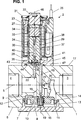
Membranventil für gasförmige und flüssige Medien, mit einem Ventilkörper (1), der mindestens einen Eingang (3) und einen Ausgang (4) für das Medium, einen Ventilsitz (9), eine gegen diesen andrückbare Membran (11) und einen Ventilraum mit einem Vorraum (12) und einem Rückraum (8) aufweist, der an einer Unterseite (6) des Ventilkörpers (1) vorgesehen und von der Membran (11) und einem Ventildeckel (7) begrenzt ist, einem über einen Magnetkopf betätigbaren Vorsteuerventil (2), das an der dem Ventildeckel (7) gegenüberliegenden Oberseite (17) des Ventilkörpers (1) angeordnet ist und einen mittels eines Dichtkörpers (41) verschließbaren Pilotventilsitz (30) aufweist, dem ein zum Ausgang (4) führender Vorsteuerabgang (22) zugehörig ist und dessen Durchgangsquerschnitt wesentlich kleiner ist als der Durchgangsquerschnitt des Ventilsitzes (9) im Ventilkörper (1), einem Vorsteuerkanal (16), der im mittleren Teil des Ventilkörpers (1) ausgebildet ist und sich vom Rückraum (8) an der Unterseite (6) zur Oberseite (17) des Ventilkörpers (1) erstreckt und zu einem Ankerraum (35) des Vorsteuerventils (2) führt, und einer Zulaufdüse (20), die vom Eingang (3) in den Vorsteuerkanal (16) einmündet und deren Durchgangsquerschnitt kleiner ist als der Durchgangsquerschnitt des Pilotventilsitzes (30).Diaphragm valve for gaseous and liquid media, comprising a valve body (1) having at least one inlet (3) and an outlet (4) for the medium, a valve seat (9), a pressureable against this membrane (11) and a valve chamber with a Anteroom (12) and a rear space (8) which is provided on an underside (6) of the valve body (1) and of the membrane (11) and a valve cover (7) is limited, a actuatable via a magnetic head pilot valve (2) which is arranged on the upper side (17) of the valve body (1) opposite the valve cover (7) and has a pilot valve seat (30) which can be closed by means of a sealing body (41), to which a pilot control outlet (22) leading to the outlet (4) is associated and whose passage cross section is substantially smaller than the passage cross section of the valve seat (9) in the valve body (1), a pilot channel (16) which is formed in the middle part of the valve body (1) and from the rear space (8). extends at the bottom (6) to the top (17) of the valve body (1) and leads to an armature space (35) of the pilot valve (2), and an inlet nozzle (20) from the input (3) into the pilot channel (16) opens and whose passage cross section is smaller than the passage cross section of the pilot valve seat (30).
Description
Die Erfindung betrifft ein Membranventil für gasförmige und flüssige Medien, das einen Ventilkörper, der mindestens einen Eingang und einen Ausgang für das Medium, einen Ventilsitz, eine gegen diesen andrückbare Membran und einen Ventilraum aufweist, der von der Membran und einem Ventildeckel begrenzt ist. Dem Membranventil ist ein über einen Magnetkopf betätigbares Vorsteuerventil zugehörig, das einen mittels eines Dichtkörpers verschließbaren Pilotventilsitz aufweist, dessen Durchgangsquerschnitt wesentlich kleiner ist als der Durchgangsquerschnitt des Ventilsitzes im Ventilkörper. Zudem sind dem Ventil ein mit dem Ventilkörpereingang korrespondierender Vorsteuerkanal und ein zum Ventilkörperausgang führender Vorsteuerabgang zugehörig.The invention relates to a gaseous and liquid media diaphragm valve comprising a valve body having at least one inlet and an outlet for the medium, a valve seat, a pressureable diaphragm against this and a valve space bounded by the diaphragm and a valve cover. The diaphragm valve is associated with a controllable via a magnetic head pilot valve having a closable by means of a sealing body pilot valve seat whose passage cross section is substantially smaller than the passage cross section of the valve seat in the valve body. In addition, the valve is associated with a corresponding with the valve body input pilot channel and leading to the valve body output pilot output.
Die
Die
Bei einem anderen bewährten Membranventil (Typ MG 252) aus der Serie der Anmelderin sind ein Membranventilsitz, eine Membran und ein Vorsteuerventil ebenfalls an der Oberseite eines Ventilkörpers angeordnet, wodurch ein entsprechender Platzbedarf benötigt wird. Der Pilotventilsitz ist bei diesem Ventil direkt an einem Stützkörper der axial verlagerbaren Membran ausgebildet.Another proven diaphragm valve (type MG 252) of the applicant's series, a diaphragm valve seat, a diaphragm and a pilot valve are also arranged on the upper side of a valve body, whereby a corresponding space requirement is needed. The pilot valve seat is formed in this valve directly to a support body of the axially displaceable membrane.
Zum allgemeinen Stand der Technik werden noch die
Die Aufgabe der Erfindung besteht darin, ein Membranventil der eingangs beschriebenen Art dahingehend weiterzubilden, dass mit einfachen Mitteln und geringem Energiebedarf eine leichtgängige und schnelle Ventilschaltung und hohe Funktionstüchtigkeit sowie eine platzsparende Bauform erzielt wird.The object of the invention is to develop a diaphragm valve of the type described above to the effect that with simple means and low energy consumption a smooth and fast valve switching and high functionality and a space-saving design is achieved.
Diese Aufgabe wird erfindungsgemäß durch die Merkmale des Anspruchs 1 gelöst.This object is achieved by the features of
Zweckmäßige Ausgestaltungen und Weiterbildungen der Erfindung sind durch die Merkmale der Unteransprüche gekennzeichnet.Expedient refinements and developments of the invention are characterized by the features of the subclaims.
Weitere Vorteile und wesentliche Einzelheiten der Erfindung sind der nachfolgenden Beschreibung und der Zeichnung zu entnehmen, die in schematischer Darstellung eine bevorzugte Ausführungsform als Beispiel zeigt. Es stellen dar:Further advantages and essential details of the invention will become apparent from the following description and the drawings, which shows a schematic representation of a preferred embodiment as an example. They show:
Das in der Zeichnung dargestellte Membranventil ist für gasförmige und flüssige Medien vorgesehen und weist einen Ventilkörper
An einer zeichnerischen Unterseite
Die Membran
Der Rohrteil
Das Vorsteuerventil
Der Magnetkern befindet sich in der axialen Mitte im oberen Bereich des Gehäuses
Der von der Elektrospule
Der Pilotventilsitz
Bei der in der
Damit das Membranventil von der Verschlussposition in die in der
Durch den Dauermagneten
Wenn das Ventil geschlossen werden soll, wird der Elektrospule
Die Aktivierung des Magnetkopfes über entsprechende elektrische Spannungsimpulse zum Öffnen und Schließen des erfindungsgemäßen Ventils kann sehr schnell in der Größenordnung von etwa 10 bis 15 Millisekunden (ms) erfolgen. Das heißt, das Ventil kann in kürzester Zeit stets und mit äußerst wenig Energie geschaltet werden. Zudem kann das Ventil auf Grund der speziellen Membrananordnung auf der dem Vorsteuerventil
Claims (10)
Priority Applications (1)
| Application Number | Priority Date | Filing Date | Title |
|---|---|---|---|
| DE102012024944.6A DE102012024944B4 (en) | 2012-12-19 | 2012-12-19 | diaphragm valve |
Applications Claiming Priority (1)
| Application Number | Priority Date | Filing Date | Title |
|---|---|---|---|
| DE102012024944.6A DE102012024944B4 (en) | 2012-12-19 | 2012-12-19 | diaphragm valve |
Publications (2)
| Publication Number | Publication Date |
|---|---|
| DE102012024944A1 DE102012024944A1 (en) | 2014-06-26 |
| DE102012024944B4 true DE102012024944B4 (en) | 2015-08-06 |
Family
ID=50878264
Family Applications (1)
| Application Number | Title | Priority Date | Filing Date |
|---|---|---|---|
| DE102012024944.6A Active DE102012024944B4 (en) | 2012-12-19 | 2012-12-19 | diaphragm valve |
Country Status (1)
| Country | Link |
|---|---|
| DE (1) | DE102012024944B4 (en) |
Families Citing this family (2)
| Publication number | Priority date | Publication date | Assignee | Title |
|---|---|---|---|---|
| DE102013017259B4 (en) * | 2013-10-17 | 2022-02-10 | Staiger Gmbh & Co. Kg | Valve |
| CN105952917B (en) * | 2016-06-30 | 2018-08-28 | 慈溪市天行电器有限公司 | A kind of supporting structure and the moving-coil type gas proportion valve with the supporting structure |
Citations (4)
| Publication number | Priority date | Publication date | Assignee | Title |
|---|---|---|---|---|
| DE3410839A1 (en) * | 1983-03-29 | 1984-10-11 | Elbi International S.p.A., Regina Margherita-Collegno, Turin/Torino | Electric valve, especially for cleaning machines |
| DE3933747A1 (en) * | 1989-10-10 | 1991-04-11 | Staiger Steuerungstech | Diaphragm-valve with improved pilot-valve connection - has spiral coupling-tube between pilot and outlet reducing wear |
| JPH11280937A (en) * | 1998-03-27 | 1999-10-15 | Keihin Corp | Constant flow solenoid valve |
| US7481412B2 (en) * | 2004-11-30 | 2009-01-27 | Keihin Corporation | Solenoid-operated cutoff valve for use with fuel cells |
-
2012
- 2012-12-19 DE DE102012024944.6A patent/DE102012024944B4/en active Active
Patent Citations (4)
| Publication number | Priority date | Publication date | Assignee | Title |
|---|---|---|---|---|
| DE3410839A1 (en) * | 1983-03-29 | 1984-10-11 | Elbi International S.p.A., Regina Margherita-Collegno, Turin/Torino | Electric valve, especially for cleaning machines |
| DE3933747A1 (en) * | 1989-10-10 | 1991-04-11 | Staiger Steuerungstech | Diaphragm-valve with improved pilot-valve connection - has spiral coupling-tube between pilot and outlet reducing wear |
| JPH11280937A (en) * | 1998-03-27 | 1999-10-15 | Keihin Corp | Constant flow solenoid valve |
| US7481412B2 (en) * | 2004-11-30 | 2009-01-27 | Keihin Corporation | Solenoid-operated cutoff valve for use with fuel cells |
Non-Patent Citations (1)
| Title |
|---|
| Staiger GmbH & Co.KG: Katalog D2 2001 Vorgesteuerte Ventile. 74391 Erligheim, DE, 2001. - Firmenschrift * |
Also Published As
| Publication number | Publication date |
|---|---|
| DE102012024944A1 (en) | 2014-06-26 |
Similar Documents
| Publication | Publication Date | Title |
|---|---|---|
| DE102008051759B3 (en) | Tubular valve device | |
| DE69509622T2 (en) | Solenoid valve for irrigation control units | |
| DE102009019554B3 (en) | Proportional throttle valve | |
| WO2001007356A1 (en) | Dispensing system for petrol-pumps | |
| DE3600498C2 (en) | ||
| DE202016103273U1 (en) | A switching mechanism for controlling the water flow direction with pulsed electromagnetic valve and a shower head | |
| DE102012024944B4 (en) | diaphragm valve | |
| DE102008017764B4 (en) | Valve | |
| DE202016000441U1 (en) | Valve | |
| DE102017208270A1 (en) | delivery unit | |
| DE102010044442B4 (en) | Electromagnet valve device with two working connections | |
| DE202012012161U1 (en) | diaphragm valve | |
| DE2712491C2 (en) | Electromagnetically operated, pressure-controlled valve | |
| EP1870621B1 (en) | Valve for controlling fluids | |
| DE19729553A1 (en) | Coaxial valve with check valve | |
| DE102009055118B4 (en) | Solenoid valve and driver assistance device | |
| WO2011076471A1 (en) | Magnetic valve and driver assistance device having such a magnetic valve | |
| EP0936317A1 (en) | Solenoid valve, in particular for sanitary appliances | |
| DE10030059A1 (en) | Control unit to hold and sensitively lower load, especially for industrial truck; has throttle valve with electromagnet coupled to control piston with electro-proportional control | |
| EP2469140B1 (en) | Valve | |
| DE102016000731B4 (en) | Valve | |
| DE102006053314B9 (en) | electromagnet | |
| EP2871353B1 (en) | Valve for metering fluid | |
| DE102016112410B4 (en) | Fluid valve with axial flow | |
| EP3632398B1 (en) | Whirlpool nozzle |
Legal Events
| Date | Code | Title | Description |
|---|---|---|---|
| R012 | Request for examination validly filed | ||
| R016 | Response to examination communication | ||
| R018 | Grant decision by examination section/examining division | ||
| R020 | Patent grant now final |