DE102011121366A1 - microtome - Google Patents
microtome Download PDFInfo
- Publication number
- DE102011121366A1 DE102011121366A1 DE201110121366 DE102011121366A DE102011121366A1 DE 102011121366 A1 DE102011121366 A1 DE 102011121366A1 DE 201110121366 DE201110121366 DE 201110121366 DE 102011121366 A DE102011121366 A DE 102011121366A DE 102011121366 A1 DE102011121366 A1 DE 102011121366A1
- Authority
- DE
- Germany
- Prior art keywords
- nozzle body
- blade
- microtome according
- microtome
- suction
- Prior art date
- Legal status (The legal status is an assumption and is not a legal conclusion. Google has not performed a legal analysis and makes no representation as to the accuracy of the status listed.)
- Withdrawn
Links
Images
Classifications
-
- G—PHYSICS
- G01—MEASURING; TESTING
- G01N—INVESTIGATING OR ANALYSING MATERIALS BY DETERMINING THEIR CHEMICAL OR PHYSICAL PROPERTIES
- G01N1/00—Sampling; Preparing specimens for investigation
- G01N1/02—Devices for withdrawing samples
- G01N1/04—Devices for withdrawing samples in the solid state, e.g. by cutting
- G01N1/06—Devices for withdrawing samples in the solid state, e.g. by cutting providing a thin slice, e.g. microtome
-
- Y—GENERAL TAGGING OF NEW TECHNOLOGICAL DEVELOPMENTS; GENERAL TAGGING OF CROSS-SECTIONAL TECHNOLOGIES SPANNING OVER SEVERAL SECTIONS OF THE IPC; TECHNICAL SUBJECTS COVERED BY FORMER USPC CROSS-REFERENCE ART COLLECTIONS [XRACs] AND DIGESTS
- Y10—TECHNICAL SUBJECTS COVERED BY FORMER USPC
- Y10S—TECHNICAL SUBJECTS COVERED BY FORMER USPC CROSS-REFERENCE ART COLLECTIONS [XRACs] AND DIGESTS
- Y10S83/00—Cutting
- Y10S83/9155—Microtome
-
- Y—GENERAL TAGGING OF NEW TECHNOLOGICAL DEVELOPMENTS; GENERAL TAGGING OF CROSS-SECTIONAL TECHNOLOGIES SPANNING OVER SEVERAL SECTIONS OF THE IPC; TECHNICAL SUBJECTS COVERED BY FORMER USPC CROSS-REFERENCE ART COLLECTIONS [XRACs] AND DIGESTS
- Y10—TECHNICAL SUBJECTS COVERED BY FORMER USPC
- Y10T—TECHNICAL SUBJECTS COVERED BY FORMER US CLASSIFICATION
- Y10T83/00—Cutting
- Y10T83/202—With product handling means
- Y10T83/2066—By fluid current
- Y10T83/207—By suction means
Abstract
Ein Mikrotom besitzt einen Klingenhalter, an dem eine Klinge gelagert ist, eine Schnittstrecker-Vorrichtung, mittels der ein mittels der Klinge erzeugtes Schnittpräparat abstütztbar ist, und eine Saugvorrichtung, mittels der das Schnittpräparat ansaugbar und abführbar ist. Die Saugvorrichtung weist eine Düse mit einem verstellbar gelagerten Düsenkörper und einen Saugkanal auf. Dabei ist vorgesehen, dass die Schnittstrecker-Vorrichtung an dem Düsenkörper gelagert und zusammen mit diesen verstellbar und insbesondere schwenkbar ist.A microtome has a blade holder on which a blade is mounted, a cutting device by means of which a cutting preparation produced by means of the blade can be supported, and a suction device by means of which the cutting preparation can be sucked and discharged. The suction device has a nozzle with an adjustably mounted nozzle body and a suction channel. It is provided that the Schnittstrecker device is mounted on the nozzle body and together with these adjustable and in particular pivotable.
Description
Die Erfindung betrifft ein Mikrotom mit einem Klingenhalter, an dem eine Klinge gelagert ist, einer Schnittstrecker-Vorrichtung, mittels der ein mittels der Klinge erzeugtes Schnittpräparat abstützbar ist, und einer Saugvorrichtung, mittels der das Schnittpräparat ansaugbar und abführbar ist, wobei die Saugvorrichtung eine Düse mit einem verstellbar gelagerten Düsenkörper und einem Saugkanal aufweist.The invention relates to a microtome with a blade holder, on which a blade is mounted, a Schnittstrecker device, by means of which a blade produced by the cutting preparation can be supported, and a suction device, by means of which the Schnittpräparat is sucked and discharged, wherein the suction device is a nozzle having an adjustably mounted nozzle body and a suction channel.
Ein Mikrotom ist ein Schneidegerät, mit dem sich von einem Körper, beispielsweise biologischem Gewebe, sehr dünne Schnittpräparate abschneiden lassen, die dann untersucht werden. Neben den Anwendungen in der Medizin und Biologie werden Mikrotome auch zur Untersuchung von Kunststoffen eingesetzt.A microtome is a cutting device that can be used to cut very thin sections from a body, such as biological tissue, which are then examined. In addition to applications in medicine and biology, microtomes are also used to study plastics.
Ein Schnittpräparat hat üblicherweise eine Dicke von 10–4 m bis 10–7 m. Aufgrund dieser geringen Dicke neigen die Schnittpräparate dazu, sich während des Schnittvorgangs zu verformen und insbesondere sich zu wellen oder sogar zu verklumpen. Um dies zu verhindern oder zumindest zu erschweren, ist eine sogenannte Schnittstrecker-Vorrichtung bekannt, die üblicherweise oberhalb der Klinge angeordnet ist und mit dieser einen spaltförmigen Durchlass bildet, durch den das Schnittpräparat hindurchgeführt wird, wobei auf das Schnittpräparat eine geringe Kraft ausgeübt wird, die es in seiner Form stabilisieren soll. Eine entsprechende Schnittstrecker-Vorrichtung ist in verschiedenen Ausgestaltungen bekannt.A section usually has a thickness of 10 -4 m to 10 -7 m. Because of this small thickness, the cut preparations tend to deform during the cutting process and in particular to rippling or even clumping. To prevent or at least complicate this, a so-called Schnittstrecker device is known, which is usually located above the blade and forms with this a gap-shaped passage through which the cutting preparation is passed, wherein on the Schnittpräparat a small force is applied, the to stabilize it in its form. A corresponding Schnittstrecker device is known in various configurations.
Wenn sich das Schnittpräparat trotzt der Verwendung einer Schnittstrecker-Vorrichtung verformt haben sollte, ist es für die weitere Untersuchung üblicherweise nicht mehr geeignet und muss abgeführt bzw. entsorgt werden. Es ist bekannt, zu diesem Zweck eine Saugvorrichtung einzusetzen, die eine Düse mit einem verstellbar gelagerten Düsenkörper und einen Saugkanal aufweist, über den die Düse an eine Unterdruckquelle angeschlossen ist. Der Düsenkörper und somit die Düse sind verstellbar gelagert und können in eine Saugposition gebracht werden, in der eine Düsenöffnung nahe der Klinge angeordnet ist, um ein unbrauchbares Schnittpräparat anzusaugen. Die durch die Saugvorrichtung erzeugbare Saugkraft kann darüber hinaus auch zur Unterstützung der Schnittstreckung eingesetzt werden. Zu Reinigungszwecken ist es möglich, den Düsenkörper in eine Nicht-Funktionsstellung zu bringen, in der die Düse zur Reinigung gut zugänglich ist.If the cutting specimen should have deformed, contrary to the use of a cutting device, it is usually no longer suitable for further examination and must be removed or disposed of. It is known to use for this purpose a suction device having a nozzle with an adjustably mounted nozzle body and a suction channel through which the nozzle is connected to a vacuum source. The nozzle body and thus the nozzle are adjustably mounted and can be brought into a suction position in which a nozzle opening is arranged near the blade to suck in an unusable cutting preparation. In addition, the suction force that can be generated by the suction device can also be used to assist the cutting extension. For cleaning purposes, it is possible to bring the nozzle body in a non-functional position in which the nozzle is easily accessible for cleaning.
Auch die Schnittstrecker-Vorrichtung ist an einem verstellbaren Träger gehalten und kann zwischen einer Funktionsstellung, in der sie zusammen mit der Klinge auf das Schnittpräparat einwirkt, und eine Nicht-Funktionsstellung verstellt werden, in der die Schnittstrecker-Vorrichtung gereinigt werden kann.Also, the cut expander device is held on an adjustable support and can be adjusted between a functional position in which it interacts with the blade on the cutting preparation, and a non-functional position in which the Schnittstrecker device can be cleaned.
Da der Bauraum für die verstellbare Lagerung einerseits der Schnittsstrecker-Vorrichtung und andererseits des Düsenkörpers stark begrenzt ist, ist die verstellbare Lagerung für diese beiden Baueinheiten konstruktiv aufwändig und kostenmäßig ungünstig.Since the space for the adjustable storage on the one hand the Schnittstrecker device and the other part of the nozzle body is severely limited, the adjustable storage for these two units is structurally complex and unfavorable in terms of cost.
Der Erfindung liegt die Aufgabe zugrunde, ein Mikrotom der genannten Art zu schaffen, bei dem in konstruktiv einfacher Weise eine Verstellung des Düsenkörpers und der Schnittstrecker-Vorrichtung verwirklicht ist.The invention has for its object to provide a microtome of the type mentioned, in which an adjustment of the nozzle body and the Schnittstrecker device is realized in a structurally simple manner.
Diese Aufgabe wird erfindungsgemäß durch ein Mikrotom mit den Merkmalen des Anspruchs 1 gelöst. Dabei ist vorgesehen, dass die Schnittstrecker-Vorrichtung an dem Düsenkörper gelagert und zusammen mit diesem verstellbar ist.This object is achieved by a microtome with the features of claim 1. It is provided that the Schnittstrecker device is mounted on the nozzle body and is adjustable together with this.
Erfindungsgemäß wird von der Grundüberlegung ausgegangen, für die Schnittstrecker-Vorrichtung und den Düsenkörper nicht jeweils eine eigene Verstellvorrichtung vorzusehen, sondern die Schnittstrecker-Vorrichtung an dem Düsenkörper mittelbar oder unmittelbar zu lagern. Da der Düsenkörper verstellbar und insbesondere um ein Schwenklager schwenkbar gelagert ist, wird auch die Schnittstrecker-Vorrichtung verstellt und von der Klinge entfernt, wenn der Düsenkörper verstellt wird. Auf diese Weise ist nur eine gemeinsame Verstellvorrichtung notwendig, wodurch der konstruktive Aufbau erleichtert ist. Darüber hinaus kann der beim Mikrotom stark begrenzte Bauraum besser ausgenutzt werden.According to the invention, it is assumed that the basic idea is not to provide a separate adjusting device for the cutting device and the nozzle body, but to mount the cutting device directly or indirectly on the nozzle body. Since the nozzle body is adjustable and in particular pivotally mounted about a pivot bearing, and the Schnittstrecker device is adjusted and removed from the blade when the nozzle body is adjusted. In this way, only one common adjustment is necessary, whereby the structural design is facilitated. In addition, the space used in the microtome can be better utilized.
In bevorzugter Ausgestaltung der Erfindung ist vorgesehen, dass der Düsenkörper zusammen mit der Schnittstrecker-Vorrichtung an einem Schwenklager schwenkbar gelagert ist.In a preferred embodiment of the invention it is provided that the nozzle body is pivotally mounted together with the Schnittstrecker device on a pivot bearing.
Dabei kann in Weiterbildung der Erfindung vorgesehen sein, dass der Saugkanal durch das Schwenklager verläuft, wodurch für den Saugkanal nur ein geringer Bauraum notwendig ist.It can be provided in a further development of the invention that the suction passage extends through the pivot bearing, whereby only a small space is necessary for the suction channel.
Das Schwenklager kann eine Aufnahme beispielsweise in Form einer kreiszylindrischen Bohrung besitzen, in die ein im Querschnitt kreiszylindrisches Rohrteil vorzugsweise unter enger Passung drehbar eingesetzt ist. Der Düsenkörper kann an dem Rohrteil gehalten sein und mit diesem in der Aufnahmebohrung schwenken.The pivot bearing may have a receptacle, for example in the form of a circular cylindrical bore, in which a circular cylindrical cross-section tube part is preferably rotatably inserted under close fit. The nozzle body may be held on the pipe part and pivot with this in the receiving bore.
Die Düse besitzt eine Ansaugöffnung, die nahe der Schneide und insbesondere versetzt zu deren Schneidkante angeordnet ist und die die Mündung des Saugkanals darstellt. Der Saugkanal kann dabei zumindest abschnittsweise in dem Düsenkörper angeordnet sein und mit dem Innenraum des Rohrteils insbesondere über einen Durchlass in der Wandung des Rohrteils in strömungstechnischer Verbindung stehen. In der Bohrung bzw. der Aufnahme kann mittels eines Unterdruckerzeugers ein Unterdruck erzeugt werden, der dann auch in dem Innenraum des Rohrteils sowie in dem im Düsenkörper ausgebildeten Abschnitt des Saugkanals und somit an der Ansaugöffnung des Düsenkörpers wirksam ist.The nozzle has a suction opening, which is arranged near the cutting edge and in particular offset from the cutting edge and which represents the mouth of the suction channel. The suction channel can thereby at least partially in the nozzle body be arranged and in fluid communication with the interior of the pipe part in particular via a passage in the wall of the pipe part. In the bore or the receptacle, a negative pressure can be generated by means of a vacuum generator, which is then effective in the interior of the pipe part and in the nozzle body formed in the portion of the suction channel and thus at the suction port of the nozzle body.
Um den Düsenkörper und die Schnittstrecker-Vorrichtung in einfach Weise reinigen zu können, kann in Weiterbildung der Erfindung vorgesehen sein, dass das Rohrteil aus der Ausnahme entnehmbar ist. Somit kann das Rohrteil mit dem Düsenkörper und der Schnittstrecker-Vorrichtung entnommen und an einem Reinigungsplatz gereinigt werden. Die Entnahme des Rohrteils aus der Aufnahme erfolgt in einfacher Weise dadurch, dass das Rohrteil in seiner Längsrichtung aus der Aufnahme herausgezogen und nach der Reinigung wieder entsprechend eingesteckt wird. Eine Entnahme des Rohrteils mit dem Düsenkörper und der Schnittstrecker-Vorrichtung ist auch dann sinnvoll, wenn der Benutzer während des Schneidvorgangs unmittelbaren Zugriff auf das Schnittpräparat benötigt, wobei die genannten Bauteile im Weg wären. Auf diese Weise ist die Handhabung vereinfacht.In order to clean the nozzle body and the Schnittstrecker device in a simple manner, can be provided in a further development of the invention that the tube part can be removed from the exception. Thus, the pipe part can be removed with the nozzle body and the Schnittstrecker device and cleaned at a cleaning station. The removal of the pipe part from the receptacle takes place in a simple manner in that the pipe part is pulled out in its longitudinal direction from the receptacle and plugged in again according to the cleaning. A removal of the pipe part with the nozzle body and the Schnittstrecker device is also useful if the user needs during the cutting process immediate access to the Schnittpräparat, said components would be in the way. In this way, the handling is simplified.
In bevorzugter Ausgestaltung der Erfindung ist vorgesehen, dass die Schnittstrecker-Vorrichtung auf der der Klinge abgewandten Seite des Düsenkörpers angeordnet ist. Wenn sich die Schnittstrecker-Vorrichtung in ihrer Funktionsstellung befindet, ist sie um ein geringes Maß oberhalb der Schneidkante der Klinge angeordnet. Der Düsenkörper mit seiner Ansaugöffnung befindet sich dabei zwischen der Klinge und der Schnittstrecker-Vorrichtung, so dass zuverlässig sicher gestellt ist, dass ein unbrauchbares Schnittpräparat bei Bedarf aufgesaugt werden kann.In a preferred embodiment of the invention it is provided that the Schnittstrecker device is arranged on the side facing away from the blade of the nozzle body. When the cut expander device is in its operative position, it is positioned a short distance above the cutting edge of the blade. The nozzle body with its suction opening is located between the blade and the Schnittstrecker device, so that it is reliably ensured that an unusable slice preparation can be absorbed if necessary.
Wenn das Mikrotom nicht benutzt wird, muss die Klinge abgedeckt werden, um eine Verletzung von Personen zu verhindern. Zu diesem Zweck ist es bekannt, auf die Klinge eine schuh- oder hülsenförmige Abdeckung, den sogenannten Fingerschutz, aufzusetzen. Um das Mikrotom in Betrieb zu nehmen, muss der Fingerschutz zunächst abgenommen werden, wobei die Gefahr besteht, dass er verloren geht, da er als loses Einzelteil vorliegt. Erfindungsgemäß kann vorgesehen sein, dass der Fingerschutz in verstellbarer Weise an der Schnittstrecker-Vorrichtung gelagert ist. Der Benutzer kann den Fingerschutz zwischen einer Schutzposition, in der er die Klinge zumindest teilweise abdeckt und den Benutzer schützt, und einer Freigabeposition verstellen, in der die Klinge freiliegt und das gewünschte Schnittpräparat schneiden kann. Die Verstellung des Fingerschutzes kann durch eine lineare oder gekrümmte Verstellbewegung erfolgen, vorzugsweise ist vorgesehen, dass der Fingerschutz schwenkbar an der Schnittstrecker-Vorrichtung gelagert ist.If the microtome is not used, the blade must be covered to prevent injury to persons. For this purpose, it is known to put on the blade a shoe or sleeve-shaped cover, the so-called finger protection. In order to put the microtome into operation, the finger guard must first be removed, with the risk that it will be lost because it is present as a loose individual part. According to the invention it can be provided that the finger guard is mounted in an adjustable manner on the Schnittstrecker device. The user may adjust the finger guard between a protective position in which it at least partially covers the blade and protects the user, and a release position in which the blade is exposed and can cut the desired cutting preparation. The adjustment of the finger guard can be done by a linear or curved adjustment, it is preferably provided that the finger guard is pivotally mounted on the Schnittstrecker device.
Bei dem Fingerschutz kann es sich um einen schwenkbaren Bügel handeln, der einerseits eine hohe Stabilität besitzt und andererseits die Klinge sicher abdecken kann. In Weiterbildung der Erfindung kann an dem Fingerschutz ein Griffteil ausgebildet sein, an dem der Benutzer den Fingerschutz und damit die Schnittstrecker-Vorrichtung und den Düsenkörper ergreifen und um das Schwenklager von der Klinge wegschwenken sowie aus dem Schwenklager herausziehen kann.The finger guard can be a swiveling bracket which, on the one hand, has high stability and, on the other hand, can safely cover the blade. In a further development of the invention may be formed on the finger guard, a handle on which the user grip the finger guard and thus the Schnittstrecker device and the nozzle body and pivot about the pivot bearing of the blade and can pull out of the pivot bearing.
Weitere Einzelheiten und Merkmale der Erfindung sind aus der folgenden Beschreibung eines Ausführungsbeispiels unter Bezugnahme auf die Zeichnung ersichtlich. Es zeigen:Further details and features of the invention will become apparent from the following description of an embodiment with reference to the drawings. Show it:
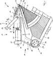
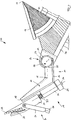
Ein in den
An dem Lagerteil
Das Rohrteil
Auf der der Klinge
Das Halteteil
Zwischen der Unterseite des Halteteils
An dem Halteteil
Zusätzlich ist an dem Bügel
Claims (11)
Priority Applications (7)
| Application Number | Priority Date | Filing Date | Title |
|---|---|---|---|
| DE201110121366 DE102011121366A1 (en) | 2011-12-19 | 2011-12-19 | microtome |
| CN201280025865.2A CN103562700B (en) | 2011-12-19 | 2012-12-06 | Slicer |
| JP2014546344A JP6025860B2 (en) | 2011-12-19 | 2012-12-06 | Microtome |
| ES12799071.1T ES2541108T3 (en) | 2011-12-19 | 2012-12-06 | Microtome |
| PCT/EP2012/005043 WO2013091786A1 (en) | 2011-12-19 | 2012-12-06 | Microtome |
| US14/237,351 US9279745B2 (en) | 2011-12-19 | 2012-12-06 | Microtome |
| EP20120799071 EP2678656B1 (en) | 2011-12-19 | 2012-12-06 | Microtome |
Applications Claiming Priority (1)
| Application Number | Priority Date | Filing Date | Title |
|---|---|---|---|
| DE201110121366 DE102011121366A1 (en) | 2011-12-19 | 2011-12-19 | microtome |
Publications (1)
| Publication Number | Publication Date |
|---|---|
| DE102011121366A1 true DE102011121366A1 (en) | 2013-06-20 |
Family
ID=47351558
Family Applications (1)
| Application Number | Title | Priority Date | Filing Date |
|---|---|---|---|
| DE201110121366 Withdrawn DE102011121366A1 (en) | 2011-12-19 | 2011-12-19 | microtome |
Country Status (7)
| Country | Link |
|---|---|
| US (1) | US9279745B2 (en) |
| EP (1) | EP2678656B1 (en) |
| JP (1) | JP6025860B2 (en) |
| CN (1) | CN103562700B (en) |
| DE (1) | DE102011121366A1 (en) |
| ES (1) | ES2541108T3 (en) |
| WO (1) | WO2013091786A1 (en) |
Families Citing this family (2)
| Publication number | Priority date | Publication date | Assignee | Title |
|---|---|---|---|---|
| DE102012010275A1 (en) * | 2012-05-25 | 2013-11-28 | Microm International Gmbh | Microtome and method for controlling a protective device of a microtome |
| CN104655450B (en) * | 2015-03-19 | 2017-12-19 | 北京易泓创信商贸有限公司 | A kind of clamping sampling device |
Citations (12)
| Publication number | Priority date | Publication date | Assignee | Title |
|---|---|---|---|---|
| DE1748387U (en) * | 1957-05-13 | 1957-07-11 | Jung Ag Fabrik Fuer Praez Sapp | ADDITIONAL EQUIPMENT FOR THE KNIFE FOR MICROTOME. |
| US3649108A (en) * | 1969-11-13 | 1972-03-14 | Milwaukee Chaplet & Mfg Co Inc | Serial section photography of organic material |
| DE2506255B2 (en) * | 1975-02-14 | 1977-03-24 | C. Reichert Optische Werke Ag, Wien | ULTRAMICROTOME |
| DE8910373U1 (en) * | 1989-08-30 | 1989-10-12 | Cambridge Instruments Gmbh, 6907 Nussloch, De | |
| DE69402197T2 (en) * | 1993-06-02 | 1997-09-18 | Microm Laborgeraete Gmbh | MICRO TONE WITH SUCTION DEVICE, ESPECIALLY FOR HISTOLOGICAL WORK OR THE LIKE |
| DE69229133T2 (en) * | 1991-09-19 | 2000-01-05 | Instrumedics Inc | CRYOSTAT WITH VACUUM SYSTEM |
| EP1094310A1 (en) * | 1999-10-20 | 2001-04-25 | Bio Optica-Milano S.p.A. | A microtome with aspiration |
| DE19824024B4 (en) * | 1998-05-29 | 2006-03-30 | Microm International Gmbh | Knife holder for a microtome |
| US20070005357A1 (en) * | 2005-06-29 | 2007-01-04 | Rosalyn Moran | Telephone pathology assessment |
| JP2007187603A (en) * | 2006-01-16 | 2007-07-26 | Seiko Instruments Inc | Thin slice feed mechanism, apparatus for manufacturing thin slice and thin slice feeding method |
| DE102008000035A1 (en) * | 2008-01-10 | 2009-07-23 | Leica Biosystems Nussloch Gmbh | Device and method for separating histological sections made with a microtome |
| DE202010011369U1 (en) * | 2009-09-08 | 2010-11-18 | Microm International Gmbh | knife holder |
Family Cites Families (9)
| Publication number | Priority date | Publication date | Assignee | Title |
|---|---|---|---|---|
| US3227020A (en) * | 1963-09-23 | 1966-01-04 | Internat Equipment Co | Microtome blade holder and anti-roll means therefor |
| US4700600A (en) * | 1986-02-28 | 1987-10-20 | Pickett John E P | Microtome disposable blade apparatus |
| DE8914782U1 (en) * | 1989-12-15 | 1990-02-08 | Cambridge Instruments Gmbh, 6907 Nussloch, De | |
| DE19640045A1 (en) * | 1996-09-30 | 1998-04-02 | Microm Laborgeraete Gmbh | Knife holder for a microtome |
| DE19640044A1 (en) * | 1996-09-30 | 1998-04-02 | Microm Laborgeraete Gmbh | Cryostat microtome |
| US6644162B1 (en) * | 1998-02-18 | 2003-11-11 | Shandon Scientific Limited | Microtome |
| KR20100014563A (en) * | 2007-04-20 | 2010-02-10 | 페자 안젠 가미소리 가부시키가이샤 | Replaceable blade for microtome and means for keeping sliced specimen against curling |
| DE102008000262B4 (en) * | 2008-02-08 | 2010-07-01 | Leica Biosystems Nussloch Gmbh | Apparatus and method for filtering microtome cut waste in airflow |
| CN201173878Y (en) * | 2008-03-31 | 2008-12-31 | 武显杰 | Pathological slice blade |
-
2011
- 2011-12-19 DE DE201110121366 patent/DE102011121366A1/en not_active Withdrawn
-
2012
- 2012-12-06 US US14/237,351 patent/US9279745B2/en active Active
- 2012-12-06 CN CN201280025865.2A patent/CN103562700B/en active Active
- 2012-12-06 EP EP20120799071 patent/EP2678656B1/en active Active
- 2012-12-06 JP JP2014546344A patent/JP6025860B2/en active Active
- 2012-12-06 WO PCT/EP2012/005043 patent/WO2013091786A1/en active Application Filing
- 2012-12-06 ES ES12799071.1T patent/ES2541108T3/en active Active
Patent Citations (12)
| Publication number | Priority date | Publication date | Assignee | Title |
|---|---|---|---|---|
| DE1748387U (en) * | 1957-05-13 | 1957-07-11 | Jung Ag Fabrik Fuer Praez Sapp | ADDITIONAL EQUIPMENT FOR THE KNIFE FOR MICROTOME. |
| US3649108A (en) * | 1969-11-13 | 1972-03-14 | Milwaukee Chaplet & Mfg Co Inc | Serial section photography of organic material |
| DE2506255B2 (en) * | 1975-02-14 | 1977-03-24 | C. Reichert Optische Werke Ag, Wien | ULTRAMICROTOME |
| DE8910373U1 (en) * | 1989-08-30 | 1989-10-12 | Cambridge Instruments Gmbh, 6907 Nussloch, De | |
| DE69229133T2 (en) * | 1991-09-19 | 2000-01-05 | Instrumedics Inc | CRYOSTAT WITH VACUUM SYSTEM |
| DE69402197T2 (en) * | 1993-06-02 | 1997-09-18 | Microm Laborgeraete Gmbh | MICRO TONE WITH SUCTION DEVICE, ESPECIALLY FOR HISTOLOGICAL WORK OR THE LIKE |
| DE19824024B4 (en) * | 1998-05-29 | 2006-03-30 | Microm International Gmbh | Knife holder for a microtome |
| EP1094310A1 (en) * | 1999-10-20 | 2001-04-25 | Bio Optica-Milano S.p.A. | A microtome with aspiration |
| US20070005357A1 (en) * | 2005-06-29 | 2007-01-04 | Rosalyn Moran | Telephone pathology assessment |
| JP2007187603A (en) * | 2006-01-16 | 2007-07-26 | Seiko Instruments Inc | Thin slice feed mechanism, apparatus for manufacturing thin slice and thin slice feeding method |
| DE102008000035A1 (en) * | 2008-01-10 | 2009-07-23 | Leica Biosystems Nussloch Gmbh | Device and method for separating histological sections made with a microtome |
| DE202010011369U1 (en) * | 2009-09-08 | 2010-11-18 | Microm International Gmbh | knife holder |
Non-Patent Citations (1)
| Title |
|---|
| Übersetzung JP2007187603A * |
Also Published As
| Publication number | Publication date |
|---|---|
| CN103562700A (en) | 2014-02-05 |
| US20140190324A1 (en) | 2014-07-10 |
| CN103562700B (en) | 2017-06-09 |
| EP2678656B1 (en) | 2015-04-01 |
| EP2678656A1 (en) | 2014-01-01 |
| JP6025860B2 (en) | 2016-11-16 |
| ES2541108T3 (en) | 2015-07-16 |
| JP2015510579A (en) | 2015-04-09 |
| US9279745B2 (en) | 2016-03-08 |
| WO2013091786A1 (en) | 2013-06-27 |
Similar Documents
| Publication | Publication Date | Title |
|---|---|---|
| DE2043843C3 (en) | Device for taking samples from internal human and animal organs | |
| DE60133297T2 (en) | BIOPSY SYSTEM | |
| DE69832193T2 (en) | DEVICE FOR THE STANDARD ACCEPTANCE, STORAGE AND PROCESSING OF BIOPSY SAMPLES | |
| DE102008000262B4 (en) | Apparatus and method for filtering microtome cut waste in airflow | |
| DE69628820T2 (en) | DEVICE FOR AUTOMATED BIOPSY AND SOFT TISSUE REMOVAL | |
| EP2542204B1 (en) | Bottle holder for an injection device | |
| EP0010321A1 (en) | Device for the single-handed operation of a biopsy instrument | |
| DE102004051974A1 (en) | Knife holder for microtome blades | |
| DE2328613A1 (en) | CLOSED DEVICE FOR DRAINING LIQUIDS FROM THE HUMAN BODY | |
| EP0002038A1 (en) | Capillary container | |
| DE19603290A1 (en) | Stone trimmer for reception of stone sample for splitting on working surface | |
| EP1740096B1 (en) | Blood taking device in particular for new-born babies and small children or small animals | |
| EP2678656B1 (en) | Microtome | |
| DE102005020426B4 (en) | Coverslipper | |
| DE102010017400A1 (en) | Device for opening hard fruit, e.g. coconut, has holder for retaining hard fruit and cutting tool, where holder has two diametrically arranged retaining elements | |
| DE19714987C1 (en) | Device for isolating particles, in particular cells | |
| DE102015118430B4 (en) | Grinding device for grinding a blade | |
| DE1993223U (en) | DEVICE FOR ADJUSTING THE LIQUID LEVEL IN CUTTING COLLECTION BASINS OF ULTRAMICROTOMS. | |
| DE3019156C2 (en) | Craniotome head | |
| DE102012023493B3 (en) | earmark | |
| DE10032007A1 (en) | Ophthalmic surgical instrument with needle for taking biopsies has outer and inner housings sliding telescopically and holding cannula leading to collection vessel | |
| DE10328277A1 (en) | Flow chamber for in-vitro investigation of cell surface processes under microscope, comprises seal and spring clamp holding culture dish | |
| EP2558899B1 (en) | Micromanipulation system with protection device for capillaries | |
| EP4205850A1 (en) | Device for holding samples | |
| DE102014007518A1 (en) | Dispensing device with bottle operation |
Legal Events
| Date | Code | Title | Description |
|---|---|---|---|
| R163 | Identified publications notified | ||
| R005 | Application deemed withdrawn due to failure to request examination |