DE102011115328A1 - Method for monitoring an exhaust system - Google Patents
Method for monitoring an exhaust system Download PDFInfo
- Publication number
- DE102011115328A1 DE102011115328A1 DE102011115328A DE102011115328A DE102011115328A1 DE 102011115328 A1 DE102011115328 A1 DE 102011115328A1 DE 102011115328 A DE102011115328 A DE 102011115328A DE 102011115328 A DE102011115328 A DE 102011115328A DE 102011115328 A1 DE102011115328 A1 DE 102011115328A1
- Authority
- DE
- Germany
- Prior art keywords
- temperature profile
- temperature
- behind
- installation
- catalyst
- Prior art date
- Legal status (The legal status is an assumption and is not a legal conclusion. Google has not performed a legal analysis and makes no representation as to the accuracy of the status listed.)
- Ceased
Links
Images


Classifications
-
- F—MECHANICAL ENGINEERING; LIGHTING; HEATING; WEAPONS; BLASTING
- F01—MACHINES OR ENGINES IN GENERAL; ENGINE PLANTS IN GENERAL; STEAM ENGINES
- F01N—GAS-FLOW SILENCERS OR EXHAUST APPARATUS FOR MACHINES OR ENGINES IN GENERAL; GAS-FLOW SILENCERS OR EXHAUST APPARATUS FOR INTERNAL COMBUSTION ENGINES
- F01N11/00—Monitoring or diagnostic devices for exhaust-gas treatment apparatus, e.g. for catalytic activity
- F01N11/002—Monitoring or diagnostic devices for exhaust-gas treatment apparatus, e.g. for catalytic activity the diagnostic devices measuring or estimating temperature or pressure in, or downstream of the exhaust apparatus
- F01N11/005—Monitoring or diagnostic devices for exhaust-gas treatment apparatus, e.g. for catalytic activity the diagnostic devices measuring or estimating temperature or pressure in, or downstream of the exhaust apparatus the temperature or pressure being estimated, e.g. by means of a theoretical model
-
- F—MECHANICAL ENGINEERING; LIGHTING; HEATING; WEAPONS; BLASTING
- F01—MACHINES OR ENGINES IN GENERAL; ENGINE PLANTS IN GENERAL; STEAM ENGINES
- F01N—GAS-FLOW SILENCERS OR EXHAUST APPARATUS FOR MACHINES OR ENGINES IN GENERAL; GAS-FLOW SILENCERS OR EXHAUST APPARATUS FOR INTERNAL COMBUSTION ENGINES
- F01N3/00—Exhaust or silencing apparatus having means for purifying, rendering innocuous, or otherwise treating exhaust
- F01N3/08—Exhaust or silencing apparatus having means for purifying, rendering innocuous, or otherwise treating exhaust for rendering innocuous
- F01N3/10—Exhaust or silencing apparatus having means for purifying, rendering innocuous, or otherwise treating exhaust for rendering innocuous by thermal or catalytic conversion of noxious components of exhaust
- F01N3/18—Exhaust or silencing apparatus having means for purifying, rendering innocuous, or otherwise treating exhaust for rendering innocuous by thermal or catalytic conversion of noxious components of exhaust characterised by methods of operation; Control
- F01N3/20—Exhaust or silencing apparatus having means for purifying, rendering innocuous, or otherwise treating exhaust for rendering innocuous by thermal or catalytic conversion of noxious components of exhaust characterised by methods of operation; Control specially adapted for catalytic conversion ; Methods of operation or control of catalytic converters
- F01N3/2066—Selective catalytic reduction [SCR]
-
- G—PHYSICS
- G01—MEASURING; TESTING
- G01M—TESTING STATIC OR DYNAMIC BALANCE OF MACHINES OR STRUCTURES; TESTING OF STRUCTURES OR APPARATUS, NOT OTHERWISE PROVIDED FOR
- G01M15/00—Testing of engines
- G01M15/04—Testing internal-combustion engines
- G01M15/10—Testing internal-combustion engines by monitoring exhaust gases or combustion flame
- G01M15/102—Testing internal-combustion engines by monitoring exhaust gases or combustion flame by monitoring exhaust gases
-
- F—MECHANICAL ENGINEERING; LIGHTING; HEATING; WEAPONS; BLASTING
- F01—MACHINES OR ENGINES IN GENERAL; ENGINE PLANTS IN GENERAL; STEAM ENGINES
- F01N—GAS-FLOW SILENCERS OR EXHAUST APPARATUS FOR MACHINES OR ENGINES IN GENERAL; GAS-FLOW SILENCERS OR EXHAUST APPARATUS FOR INTERNAL COMBUSTION ENGINES
- F01N2550/00—Monitoring or diagnosing the deterioration of exhaust systems
- F01N2550/02—Catalytic activity of catalytic converters
-
- F—MECHANICAL ENGINEERING; LIGHTING; HEATING; WEAPONS; BLASTING
- F01—MACHINES OR ENGINES IN GENERAL; ENGINE PLANTS IN GENERAL; STEAM ENGINES
- F01N—GAS-FLOW SILENCERS OR EXHAUST APPARATUS FOR MACHINES OR ENGINES IN GENERAL; GAS-FLOW SILENCERS OR EXHAUST APPARATUS FOR INTERNAL COMBUSTION ENGINES
- F01N2550/00—Monitoring or diagnosing the deterioration of exhaust systems
- F01N2550/24—Determining the presence or absence of an exhaust treating device
-
- F—MECHANICAL ENGINEERING; LIGHTING; HEATING; WEAPONS; BLASTING
- F01—MACHINES OR ENGINES IN GENERAL; ENGINE PLANTS IN GENERAL; STEAM ENGINES
- F01N—GAS-FLOW SILENCERS OR EXHAUST APPARATUS FOR MACHINES OR ENGINES IN GENERAL; GAS-FLOW SILENCERS OR EXHAUST APPARATUS FOR INTERNAL COMBUSTION ENGINES
- F01N2560/00—Exhaust systems with means for detecting or measuring exhaust gas components or characteristics
- F01N2560/06—Exhaust systems with means for detecting or measuring exhaust gas components or characteristics the means being a temperature sensor
-
- F—MECHANICAL ENGINEERING; LIGHTING; HEATING; WEAPONS; BLASTING
- F01—MACHINES OR ENGINES IN GENERAL; ENGINE PLANTS IN GENERAL; STEAM ENGINES
- F01N—GAS-FLOW SILENCERS OR EXHAUST APPARATUS FOR MACHINES OR ENGINES IN GENERAL; GAS-FLOW SILENCERS OR EXHAUST APPARATUS FOR INTERNAL COMBUSTION ENGINES
- F01N2900/00—Details of electrical control or of the monitoring of the exhaust gas treating apparatus
- F01N2900/06—Parameters used for exhaust control or diagnosing
- F01N2900/14—Parameters used for exhaust control or diagnosing said parameters being related to the exhaust gas
- F01N2900/1404—Exhaust gas temperature
-
- F—MECHANICAL ENGINEERING; LIGHTING; HEATING; WEAPONS; BLASTING
- F01—MACHINES OR ENGINES IN GENERAL; ENGINE PLANTS IN GENERAL; STEAM ENGINES
- F01N—GAS-FLOW SILENCERS OR EXHAUST APPARATUS FOR MACHINES OR ENGINES IN GENERAL; GAS-FLOW SILENCERS OR EXHAUST APPARATUS FOR INTERNAL COMBUSTION ENGINES
- F01N9/00—Electrical control of exhaust gas treating apparatus
- F01N9/005—Electrical control of exhaust gas treating apparatus using models instead of sensors to determine operating characteristics of exhaust systems, e.g. calculating catalyst temperature instead of measuring it directly
-
- F—MECHANICAL ENGINEERING; LIGHTING; HEATING; WEAPONS; BLASTING
- F01—MACHINES OR ENGINES IN GENERAL; ENGINE PLANTS IN GENERAL; STEAM ENGINES
- F01N—GAS-FLOW SILENCERS OR EXHAUST APPARATUS FOR MACHINES OR ENGINES IN GENERAL; GAS-FLOW SILENCERS OR EXHAUST APPARATUS FOR INTERNAL COMBUSTION ENGINES
- F01N9/00—Electrical control of exhaust gas treating apparatus
- F01N9/007—Storing data relevant to operation of exhaust systems for later retrieval and analysis, e.g. to research exhaust system malfunctions
-
- Y—GENERAL TAGGING OF NEW TECHNOLOGICAL DEVELOPMENTS; GENERAL TAGGING OF CROSS-SECTIONAL TECHNOLOGIES SPANNING OVER SEVERAL SECTIONS OF THE IPC; TECHNICAL SUBJECTS COVERED BY FORMER USPC CROSS-REFERENCE ART COLLECTIONS [XRACs] AND DIGESTS
- Y02—TECHNOLOGIES OR APPLICATIONS FOR MITIGATION OR ADAPTATION AGAINST CLIMATE CHANGE
- Y02T—CLIMATE CHANGE MITIGATION TECHNOLOGIES RELATED TO TRANSPORTATION
- Y02T10/00—Road transport of goods or passengers
- Y02T10/10—Internal combustion engine [ICE] based vehicles
- Y02T10/12—Improving ICE efficiencies
-
- Y—GENERAL TAGGING OF NEW TECHNOLOGICAL DEVELOPMENTS; GENERAL TAGGING OF CROSS-SECTIONAL TECHNOLOGIES SPANNING OVER SEVERAL SECTIONS OF THE IPC; TECHNICAL SUBJECTS COVERED BY FORMER USPC CROSS-REFERENCE ART COLLECTIONS [XRACs] AND DIGESTS
- Y02—TECHNOLOGIES OR APPLICATIONS FOR MITIGATION OR ADAPTATION AGAINST CLIMATE CHANGE
- Y02T—CLIMATE CHANGE MITIGATION TECHNOLOGIES RELATED TO TRANSPORTATION
- Y02T10/00—Road transport of goods or passengers
- Y02T10/10—Internal combustion engine [ICE] based vehicles
- Y02T10/40—Engine management systems
Abstract
Es werden ein Verfahren und eine Anordnung zum Überwachen einer Abgasanlage (10) eines Verbrennungsmotors vorgestellt. Hierbei werden Temperaturverläufe vor und hinter einem Einbauort (16) eines Katalysators (18) gemessen, um zu bestimmen, ob ein Katalysator (18) eingebaut ist oder nicht.A method and an arrangement for monitoring an exhaust system (10) of an internal combustion engine are presented. Here, temperature traces are measured in front of and behind an installation location (16) of a catalyst (18) to determine whether a catalyst (18) is installed or not.
Description
Die Erfindung betrifft ein Verfahren und eine Anordnung zum Überwachen einer Abgasanlage.The invention relates to a method and an arrangement for monitoring an exhaust system.
Es werden Abgasanlagen verwendet, um die Schadstoffanteile der Abgase, die beim Betrieb eines Verbrennungsmotors entstehen, abzubauen. Die verbleibenden Abgase werden dann abgeleitet. Die Abgasanlage besteht regelmäßig aus mehreren Teilen, nämlich einem oder mehreren Schalldämpfern, Rohren und einem Katalysator.Exhaust systems are used to reduce the pollutant components of the exhaust gases that occur during operation of an internal combustion engine. The remaining exhaust gases are then discharged. The exhaust system regularly consists of several parts, namely one or more mufflers, pipes and a catalyst.
Insbesondere Katalysatoren dienen zur Abgasbehandlung bzw. zur Nachbehandlung, um Schadstoffemissionen im Abgas zu reduzieren. Dabei sind unterschiedliche Arten von Katalysatoren, wie bspw. Dreiwegekatalysatoren, ungeregelte Katalysatoren, Oxidationskatalysatoren und SCR-Katalysatoren, bekannt. In SCR-Katalysatoren wird bspw. als Verfahren zur Reduktion von Stickoxiden die sogenannte selektive katalytische Reduktion (SCR: Selective Catalytic Reduktion) eingesetzt.In particular, catalysts are used for exhaust gas treatment or for after-treatment in order to reduce pollutant emissions in the exhaust gas. Different types of catalysts, such as, for example, three-way catalysts, uncontrolled catalysts, oxidation catalysts and SCR catalysts, are known. In SCR catalysts, for example, the so-called selective catalytic reduction (SCR: Selective Catalytic Reduction) is used as the process for the reduction of nitrogen oxides.
Um die Funktionsfähigkeit des Katalysators zu überwachen, sind unterschiedliche Verfahren bekannt.In order to monitor the functioning of the catalyst, different methods are known.
Die Druckschrift
Aus der Druckschrift
Die Druckschrift
Um zu überprüfen, ob ein Katalysator entfernt wurde, ist es bekannt, einen Differenzdrucksensor über dem Katalysator anzuordnen. Dieser hat die Aufgabe zu erkennen, ob ein Katalysator installiert ist oder ob dieser bspw. von dem Betreiber entfernt wurde. Bei vielen Anwendungen ist der Differenzdrucksensor nur wegen der Leerrohrerkennung verbaut. Dadurch entstehen zusätzliche Kosten.In order to check whether a catalyst has been removed, it is known to arrange a differential pressure sensor over the catalyst. This has the task of recognizing whether a catalyst has been installed or whether it has been removed, for example, by the operator. In many applications, the differential pressure sensor is installed only because of the empty pipe detection. This results in additional costs.
Es wird ein Verfahren zur Überwachung der Funktionsfähigkeit einer Abgasanlage vorgestellt, das es ermöglicht zu überprüfen, ob ein Katalysator eingebaut ist oder nicht.A method for monitoring the functionality of an exhaust system is presented, which makes it possible to check whether a catalytic converter is installed or not.
Das beschriebene Verfahren dient zum Überwachen einer Abgasanlage eines Verbrennungsmotors, welche zum Ableiten von dem Verbrennungsmotor erzeugten Abgasen in Strömungsrichtung vorgesehen ist. Dabei ist in der Abgasanlage ein zum Einbau eines Katalysators geeigneter Einbauort vorgesehen, wobei ein erster Temperaturverlauf in Strömungsrichtung des Abgases vor dem Einbauort und ein zweiter Temperaturverlauf in Strömungsrichtung hinter dem Einbauort gemessen werden. Anhand des gemessenen ersten Temperaturverlaufs vor dem Einbauort wird ein erwarteter Temperaturverlauf hinter dem Einbauort ermittelt und der ermittelte erwartete Temperaturverlauf hinter dem Einbauort wird mit dem gemessenen zweiten Temperaturverlauf hinter dem Einbauort verglichen, um zu bestimmen, ob der Katalysator an dem Einbauort eingebaut ist.The method described is used to monitor an exhaust system of an internal combustion engine, which is provided for deriving exhaust gases generated in the flow direction from the internal combustion engine. In this case, a suitable installation location for installation of a catalytic converter is provided in the exhaust system, wherein a first temperature profile in the flow direction of the exhaust gas before the installation location and a second temperature profile in the flow direction behind the installation location are measured. Based on the measured first temperature profile in front of the installation location, an expected temperature profile behind the installation location is determined and the determined expected temperature profile behind the installation location is compared with the measured second temperature profile behind the installation location to determine whether the catalytic converter is installed at the installation location.
Das Verfahren wird zweckmäßigerweise während eines Temperatursprungs durchgeführt.The process is conveniently carried out during a temperature jump.
Es kann vorgesehen sein, dass der erwartete Temperaturverlauf hinter dem Einbauort mittels einer Simulation, bspw. mittels einer Online-Simulation, ermittelt wird.It can be provided that the expected temperature profile behind the installation location is determined by means of a simulation, for example by means of an online simulation.
In Ausgestaltung wird bei einer vorgebbaren Abweichung zwischen dem ermittelten erwarteten Temperaturverlauf hinter dem Einbauort und dem gemessenen zweiten Temperaturverlauf hinter dem Einbauort ein Fehler in einem Speicher gesetzt.In an embodiment, a fault is set in a memory at a predeterminable deviation between the determined expected temperature profile behind the installation location and the measured second temperature profile behind the installation location.
Dieser Speicher kann in vorgebbaren zeitlichen Abständen ausgelesen werden. This memory can be read out at predefinable time intervals.
Alternativ oder ergänzend kann der Speicher bei einem konstanten ersten Temperaturverlauf vor dem Einbauort ausgelesen werden.Alternatively or additionally, the memory can be read out at a constant first temperature profile in front of the installation location.
Es wird weiterhin eine Anordnung zum Überwachen einer Abgasanlage eines Verbrennungsmotors vorgestellt, welche zum Ableiten von dem Verbrennungsmotor erzeugten Abgasen in Strömungsrichtung vorgesehen ist. Die Anordnung dient insbesondere zur Durchführung eines Verfahrens der vorstehend beschriebenen Art. Dabei ist in der Abgasanlage ein zum Einbau eines Katalysators geeigneter Einbauort vorgesehen, wobei die Anordnung einen ersten Temperatursensor zum Messen eines ersten Temperaturverlaufs in Strömungsrichtung vor dem Einbauort und einen zweiten Temperatursensor zum Messen eines Temperaturverlaufs in Strömungsrichtung hinter dem Einbauort aufweist, wobei die Anordnung dazu ausgebildet ist, anhand des gemessenen ersten Temperaturverlaufs vor dem Einbauort einen erwarteten Temperaturverlauf hinter dem Einbauort zu ermitteln und den ermittelten erwarteten Temperaturverlauf hinter dem Einbauort mit dem gemessenen zweiten Temperaturverlauf hinter dem Einbauort zu vergleichen, um zu bestimmen, ob der Katalysator an dem Einbauort eingebaut ist oder nicht.An arrangement for monitoring an exhaust system of an internal combustion engine is presented, which is provided for discharging exhaust gases generated in the flow direction from the internal combustion engine. The arrangement is used in particular for carrying out a method of the type described above. In the exhaust system, a mounting location suitable for installation of a catalyst is provided, wherein the arrangement comprises a first temperature sensor for measuring a first temperature profile in the flow direction in front of the installation location and a second temperature sensor for measuring a Temperature course in the flow direction behind the installation location, wherein the arrangement is designed to determine an expected temperature profile behind the installation based on the measured first temperature profile before the installation location and to compare the determined expected temperature profile behind the installation location with the measured second temperature profile behind the installation location to determine whether the catalyst is installed at the installation site or not.
Die Anordnung weist in Ausgestaltung einen Speicher zum Setzen eines Fehlers bei einer vorgebbaren Abweichung zwischen dem ermittelten erwarteten Temperaturverlauf hinter dem Einbauort und dem gemessenen zweiten Temperaturverlauf hinter dem Einbauort auf.The arrangement has, in an embodiment, a memory for setting an error for a predefinable deviation between the determined expected temperature profile behind the installation location and the measured second temperature profile behind the installation location.
Das Verfahren ist insbesondere für alle Anwendungen mit SCR-Katalysatoren geeignet, wobei ein Differenzdrucksensor nicht benötigt wird.The method is particularly suitable for all applications with SCR catalysts, wherein a differential pressure sensor is not needed.
Somit ist die Möglichkeit gegeben zu überprüfen, ob ein Katalysator entfernt wurde. Eine Entfernung würde dazu führen, dass die Emissionen nicht eingehalten würden.Thus there is the possibility to check if a catalyst has been removed. A removal would result in the emissions not being met.
Mittels vorhandener Temperatursensoren vor und nach dem Katalysator werden die Temperaturverläufe ermittelt. Auf geeignete Art und Weise unter Berücksichtigung der Abgasmasse werden die Temperaturverläufe verarbeitet und miteinander verglichen. Im Moment eines Abgastemperatursprungs wird eine bestimmte zeitliche Verschiebung der beiden Temperaturverläufe erwartet. Ist dies nicht der Fall, so kann von einem entfernten Katalysator ausgegangen werden.By means of existing temperature sensors before and after the catalyst, the temperature profiles are determined. In a suitable manner, taking into account the exhaust gas mass, the temperature profiles are processed and compared with each other. At the moment of an exhaust gas temperature jump, a certain time shift of the two temperature profiles is expected. If this is not the case, it can be assumed that a catalyst is removed.
Der Einsatz eines Differenzdrucksensors über dem Katalysator, der unter anderem die Aufgabe hat zu erkennen, ob ein Katalysator installiert ist oder aber durch den Betreiber entfernt worden ist, entfällt somit. Damit werden Sensor-, Verkabelungs-, Schlauch- und Wartungskosten eingespart. Außerdem kann die Ausführung des Abgasnachbehandlungsreaktors einfacher ausfallen, da zwei Messstutzen weniger eingebaut werden müssen.The use of a differential pressure sensor over the catalyst, which has the task among other things to detect whether a catalyst is installed or has been removed by the operator, thus eliminating. This saves sensor, cabling, hose and maintenance costs. In addition, the design of the exhaust aftertreatment reactor can be simpler, since two measuring stub less need to be installed.
Weitere Vorteile und Ausgestaltungen der Erfindung ergeben sich aus der Beschreibung und der beiliegenden Zeichnung.Further advantages and embodiments of the invention will become apparent from the description and the accompanying drawings.
Es versteht sich, dass die voranstehend genannten und die nachstehend noch zu erläuternden Merkmale nicht nur in der jeweils angegebenen Kombination, sondern auch in anderen Kombinationen oder in Alleinstellung verwendbar sind, ohne den Rahmen der vorliegenden Erfindung zu verlassen.It is understood that the features mentioned above and those yet to be explained below can be used not only in the particular combination indicated, but also in other combinations or in isolation, without departing from the scope of the present invention.
Die Erfindung ist anhand von Ausführungsformen in der Zeichnung schematisch dargestellt und wird nachfolgend unter Bezugnahme auf die Zeichnung ausführlich beschrieben.The invention is schematically illustrated by means of embodiments in the drawing and will be described in detail below with reference to the drawing.
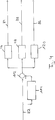
In
In Strömungsrichtung
In
Ein erster Graph
In einem zweiten Graphen
In einem dritten Graphen
Ein vierter Graph
Die vier Graphen
In
In einem ersten Block
In dem zweiten Block
In der Auswertelogik
In
Es werden Werte der Temperaturmessung vor dem Einbauort herangezogen (Signal
Liegt kein Temperatursprung bzw. liegt ein Temperatursprung unterhalb einer vorgebbaren Schwelle vor, so gibt eine erste Einheit
In
In ein ODER-Glied
Der Integrator
Während eines Temperatursprungs ergibt sich bei fehlendem Katalysator eine zu große Abweichung. Es wird die Differenz zwischen der erwarteten und der realen Temperatur nach dem Einbauort mit der Abgasmasse multipliziert und integriert.During a temperature jump results in the absence of catalyst too large a deviation. The difference between the expected and the real temperature after the installation site is multiplied by the exhaust gas mass and integrated.
Es wird somit in Ausgestaltung während eines Temperatursprungs immer geprüft, ob eine zu große Abweichung vorliegt. Ist dies der Fall, so wird dies als Fehler gespeichert. Dieser Fehler kann während eines Temperatursprungs nur als ein Fehler gezählt werden.It is thus always checked in design during a temperature jump, if there is too much deviation. If this is the case, then this is stored as an error. This error can only be counted as a fault during a temperature jump.
Es gilt: 
Es erfolgt somit eine Auswertung der Temperatursensoren im Vergleich zu einer Online-Simulation. Wenn die Simulation und das Modell abweichen, ist dies ein Fehler, was auf einen fehlenden Katalysator hinweisen kann.There is thus an evaluation of the temperature sensors in comparison to an online simulation. If the simulation and the model deviate, this is a mistake, which may indicate a missing catalyst.
Durch die Berücksichtigung der Abgasmasse funktioniert die Auswertung in jedem Motorbetriebspunkt, da der Fehler Leerrohrindikator der fehlenden Energie in der Abgasanlage entspricht.By taking into account the exhaust gas mass, the evaluation works in each engine operating point, since the error empty pipe indicator corresponds to the lack of energy in the exhaust system.
ZITATE ENTHALTEN IN DER BESCHREIBUNG QUOTES INCLUDE IN THE DESCRIPTION
Diese Liste der vom Anmelder aufgeführten Dokumente wurde automatisiert erzeugt und ist ausschließlich zur besseren Information des Lesers aufgenommen. Die Liste ist nicht Bestandteil der deutschen Patent- bzw. Gebrauchsmusteranmeldung. Das DPMA übernimmt keinerlei Haftung für etwaige Fehler oder Auslassungen.This list of the documents listed by the applicant has been generated automatically and is included solely for the better information of the reader. The list is not part of the German patent or utility model application. The DPMA assumes no liability for any errors or omissions.
Zitierte PatentliteraturCited patent literature
- DE 4027207 A1 [0005] DE 4027207 A1 [0005]
- DE 4308894 A1 [0006] DE 4308894 A1 [0006]
- DE 4211092 A1 [0007] DE 4211092 A1 [0007]
Claims (9)
Priority Applications (9)
| Application Number | Priority Date | Filing Date | Title |
|---|---|---|---|
| DE102011115328A DE102011115328A1 (en) | 2011-10-07 | 2011-10-07 | Method for monitoring an exhaust system |
| PCT/EP2012/004173 WO2013050167A1 (en) | 2011-10-07 | 2012-10-05 | A method for monitoring an exhaust system |
| US14/350,106 US9416715B2 (en) | 2011-10-07 | 2012-10-05 | Method for monitoring an exhaust system of an internal combustion engine |
| RU2014118362/06A RU2573084C2 (en) | 2011-10-07 | 2012-10-05 | Method to control exhaust gas release system |
| EP12778231.6A EP2764220B1 (en) | 2011-10-07 | 2012-10-05 | Method for monitoring an exhaust system |
| KR1020147012133A KR101914106B1 (en) | 2011-10-07 | 2012-10-05 | A method for monitoring an exhaust system |
| IN416MUN2014 IN2014MN00416A (en) | 2011-10-07 | 2012-10-05 | |
| CN201280049022.6A CN103958845B (en) | 2011-10-07 | 2012-10-05 | For monitor internal combustion engine exhaust apparatus method and perform this method component |
| HK15100924.4A HK1200894A1 (en) | 2011-10-07 | 2015-01-28 | A method for monitoring an exhaust system |
Applications Claiming Priority (1)
| Application Number | Priority Date | Filing Date | Title |
|---|---|---|---|
| DE102011115328A DE102011115328A1 (en) | 2011-10-07 | 2011-10-07 | Method for monitoring an exhaust system |
Publications (1)
| Publication Number | Publication Date |
|---|---|
| DE102011115328A1 true DE102011115328A1 (en) | 2013-04-11 |
Family
ID=47076139
Family Applications (1)
| Application Number | Title | Priority Date | Filing Date |
|---|---|---|---|
| DE102011115328A Ceased DE102011115328A1 (en) | 2011-10-07 | 2011-10-07 | Method for monitoring an exhaust system |
Country Status (9)
| Country | Link |
|---|---|
| US (1) | US9416715B2 (en) |
| EP (1) | EP2764220B1 (en) |
| KR (1) | KR101914106B1 (en) |
| CN (1) | CN103958845B (en) |
| DE (1) | DE102011115328A1 (en) |
| HK (1) | HK1200894A1 (en) |
| IN (1) | IN2014MN00416A (en) |
| RU (1) | RU2573084C2 (en) |
| WO (1) | WO2013050167A1 (en) |
Cited By (2)
| Publication number | Priority date | Publication date | Assignee | Title |
|---|---|---|---|---|
| DE102015212372A1 (en) * | 2015-07-02 | 2017-01-05 | Ford Global Technologies, Llc | Method and system for monitoring operation of a catalyst |
| DE102018222247A1 (en) * | 2018-12-19 | 2020-06-25 | Continental Automotive Gmbh | Method and device for diagnosing a particle filter arranged in the exhaust system of a gasoline-powered internal combustion engine |
Families Citing this family (9)
| Publication number | Priority date | Publication date | Assignee | Title |
|---|---|---|---|---|
| GB2511772B (en) | 2013-03-12 | 2019-01-30 | Ceramex Ltd | Testing catalytic efficiency of an exhaust component |
| GB2530203A (en) * | 2015-12-10 | 2016-03-16 | Gm Global Tech Operations Inc | A method of detecting a catalyst of a selective catalytic reduction system |
| FR3081917B1 (en) * | 2018-05-29 | 2020-06-12 | Renault S.A.S | SYSTEM AND METHOD FOR ESTIMATING THE PRESENCE OF A CATALYSIS MONOLITE OF AN EXHAUST GAS CATALYSIS SYSTEM OF AN INTERNAL COMBUSTION ENGINE FOR A MOTOR VEHICLE. |
| US11149615B2 (en) | 2018-12-25 | 2021-10-19 | Toyota Jidosha Kabushiki Kaisha | Control device for internal combustion engine |
| JP6780763B2 (en) | 2018-12-25 | 2020-11-04 | トヨタ自動車株式会社 | Internal combustion engine control device |
| JP7317170B2 (en) * | 2019-03-28 | 2023-07-28 | ヤンマーパワーテクノロジー株式会社 | engine |
| US11428181B2 (en) * | 2020-03-25 | 2022-08-30 | Cummins Inc. | Systems and methods for ultra-low NOx cold start warmup control and fault diagnosis |
| KR102615496B1 (en) | 2021-12-09 | 2023-12-20 | 주식회사 오리온이엔씨 | System for moving used nuclear fuel |
| JP2023180714A (en) * | 2022-06-10 | 2023-12-21 | トヨタ自動車株式会社 | Control device for internal combustion engine |
Citations (4)
| Publication number | Priority date | Publication date | Assignee | Title |
|---|---|---|---|---|
| DE4027207A1 (en) | 1990-08-28 | 1992-03-05 | Emitec Emissionstechnologie | MONITORING THE CATALYTIC ACTIVITY OF A CATALYST IN THE EXHAUST SYSTEM OF AN INTERNAL COMBUSTION ENGINE |
| DE4211092A1 (en) | 1992-04-03 | 1993-10-07 | Bosch Gmbh Robert | Method and device for assessing the functionality of a catalytic converter |
| DE4308894A1 (en) | 1993-03-19 | 1994-09-22 | Siemens Ag | Procedure for checking the conversion of a catalytic converter |
| US20110143449A1 (en) * | 2009-12-10 | 2011-06-16 | Cummins Ip, Inc. | Apparatus, system, and method for catalyst presence detection |
Family Cites Families (10)
| Publication number | Priority date | Publication date | Assignee | Title |
|---|---|---|---|---|
| DE10013893A1 (en) | 2000-03-21 | 2001-09-27 | Dmc2 Degussa Metals Catalysts | Method for checking the functionality of an exhaust gas purification catalytic converter |
| FR2814498B1 (en) * | 2000-09-27 | 2003-04-11 | Renault | METHOD FOR MANAGING THE OPERATION OF A PARTICLE FILTER FOR A COMBUSTION ENGINE |
| DE10247989A1 (en) * | 2002-10-15 | 2004-04-29 | Robert Bosch Gmbh | Exhaust gas cleaning of an internal combustion engine and method for cleaning its exhaust gases |
| JP4238788B2 (en) | 2004-06-21 | 2009-03-18 | トヨタ自動車株式会社 | Particulate filter abnormality judgment method |
| US7546761B2 (en) | 2005-04-12 | 2009-06-16 | Gm Global Technology Operations, Inc. | Diesel oxidation catalyst (DOC) temperature sensor rationality diagnostic |
| DE102005040906A1 (en) | 2005-08-30 | 2007-03-08 | Daimlerchrysler Ag | Method for monitoring an exhaust gas purification component |
| DE102005061872A1 (en) * | 2005-12-23 | 2007-07-05 | Robert Bosch Gmbh | Regeneration of motor vehicle internal combustion engine exhaust gas catalyst comprises use of two gas mixture sensors to control reduction agent mix |
| DK2181191T3 (en) | 2007-08-20 | 2011-05-23 | Novozymes As | Nuclease reduction |
| FR2938010A1 (en) * | 2008-11-04 | 2010-05-07 | Peugeot Citroen Automobiles Sa | METHOD FOR MONITORING A PARTICLE FILTER |
| US8720189B2 (en) * | 2011-01-26 | 2014-05-13 | GM Global Technology Operations LLC | Apparatus and method for onboard performance monitoring of oxidation catalyst |
-
2011
- 2011-10-07 DE DE102011115328A patent/DE102011115328A1/en not_active Ceased
-
2012
- 2012-10-05 KR KR1020147012133A patent/KR101914106B1/en active IP Right Grant
- 2012-10-05 US US14/350,106 patent/US9416715B2/en active Active
- 2012-10-05 RU RU2014118362/06A patent/RU2573084C2/en not_active IP Right Cessation
- 2012-10-05 CN CN201280049022.6A patent/CN103958845B/en active Active
- 2012-10-05 IN IN416MUN2014 patent/IN2014MN00416A/en unknown
- 2012-10-05 EP EP12778231.6A patent/EP2764220B1/en active Active
- 2012-10-05 WO PCT/EP2012/004173 patent/WO2013050167A1/en active Application Filing
-
2015
- 2015-01-28 HK HK15100924.4A patent/HK1200894A1/en unknown
Patent Citations (4)
| Publication number | Priority date | Publication date | Assignee | Title |
|---|---|---|---|---|
| DE4027207A1 (en) | 1990-08-28 | 1992-03-05 | Emitec Emissionstechnologie | MONITORING THE CATALYTIC ACTIVITY OF A CATALYST IN THE EXHAUST SYSTEM OF AN INTERNAL COMBUSTION ENGINE |
| DE4211092A1 (en) | 1992-04-03 | 1993-10-07 | Bosch Gmbh Robert | Method and device for assessing the functionality of a catalytic converter |
| DE4308894A1 (en) | 1993-03-19 | 1994-09-22 | Siemens Ag | Procedure for checking the conversion of a catalytic converter |
| US20110143449A1 (en) * | 2009-12-10 | 2011-06-16 | Cummins Ip, Inc. | Apparatus, system, and method for catalyst presence detection |
Cited By (4)
| Publication number | Priority date | Publication date | Assignee | Title |
|---|---|---|---|---|
| DE102015212372A1 (en) * | 2015-07-02 | 2017-01-05 | Ford Global Technologies, Llc | Method and system for monitoring operation of a catalyst |
| DE102015212372B4 (en) | 2015-07-02 | 2021-09-30 | Ford Global Technologies, Llc | Method and system for monitoring operation of a catalytic converter |
| DE102018222247A1 (en) * | 2018-12-19 | 2020-06-25 | Continental Automotive Gmbh | Method and device for diagnosing a particle filter arranged in the exhaust system of a gasoline-powered internal combustion engine |
| US11136911B2 (en) | 2018-12-19 | 2021-10-05 | Vitesco Technologies GmbH | Method and device for diagnosis of a particle filter arranged in the exhuast gas system of a petro-operated internal combustion engine |
Also Published As
| Publication number | Publication date |
|---|---|
| KR20140079454A (en) | 2014-06-26 |
| RU2573084C2 (en) | 2016-01-20 |
| CN103958845A (en) | 2014-07-30 |
| EP2764220A1 (en) | 2014-08-13 |
| RU2014118362A (en) | 2015-11-20 |
| IN2014MN00416A (en) | 2015-06-19 |
| US9416715B2 (en) | 2016-08-16 |
| US20150033837A1 (en) | 2015-02-05 |
| CN103958845B (en) | 2017-09-22 |
| EP2764220B1 (en) | 2018-07-25 |
| WO2013050167A1 (en) | 2013-04-11 |
| HK1200894A1 (en) | 2015-08-14 |
| KR101914106B1 (en) | 2018-11-01 |
Similar Documents
| Publication | Publication Date | Title |
|---|---|---|
| EP2764220B1 (en) | Method for monitoring an exhaust system | |
| DE102016218820B4 (en) | Method for diagnosing a measurement of a pressure difference | |
| EP2791493B1 (en) | Method and apparatus for monitoring exhaust gas sensor dynamics | |
| DE102009000286B4 (en) | Monitoring a particle limit value in the exhaust gas of an internal combustion engine | |
| EP3111061B1 (en) | Method for determining the aging of an oxidation catalyst in an exhaust gas aftertreatment system of an internal combustion engine, method for detecting ash in a particle filter of an exhaust gas aftertreatment system, control device, and internal combustion engine | |
| DE102007059523B4 (en) | Method and device for diagnosing a particulate filter | |
| DE102014209840A1 (en) | Method and device for diagnosing a particulate filter | |
| DE102017205361A1 (en) | Method and computer program product for diagnosing a particulate filter | |
| EP1561019A1 (en) | Method for testing at least three sensors, which detect a measurable variable for an internal combustion engine | |
| EP1724458A1 (en) | Method and apparatus for diagnosing a measured value | |
| DE102014210884B4 (en) | Determining the pump power of a pump of a secondary air system of an internal combustion engine | |
| DE102014209810A1 (en) | Method and device for detecting a soot and ash charge of a particulate filter | |
| DE102017006400A1 (en) | A method of assessing a condition of a particulate filter and exhaust system for a motor vehicle | |
| DE102011000153A1 (en) | Method for the diagnosis of exhaust gas aftertreatment | |
| DE102014209794A1 (en) | Method and device for the diagnosis of a removal of a component of an emission control system | |
| DE102011089503A1 (en) | Diagnostic procedure for particulate filter arranged in effluent stream of combustion engine, involves comparing detected particle mass concentration with selected particle mass concentration threshold value | |
| WO2018041502A1 (en) | Method for detecting the ready-to-measure state of a particle sensor of an internal combustion engine | |
| DE102005034270A1 (en) | Method for diagnosing a differential pressure sensor arranged in an exhaust gas region of a combustion engine comprises evaluating the dynamic behavior of a differential pressure signal as a result of a change in exhaust gas pressure | |
| DE102014206252B4 (en) | Method and device for diagnosing the functionality of a diesel particulate filter | |
| DE102011077251B3 (en) | Diagnostic method for ammonia filter of nitrogen oxide sensor for exhaust system of diesel engine for motor car, involves deactivating filter when value of error is below threshold value | |
| DE10341454A1 (en) | Method for checking at least three sensors that detect a measurement variable in the area of an internal combustion engine | |
| DE102008023893A1 (en) | Method for diagnosing the functionality of a jumping probe | |
| DE102013226565A1 (en) | Method for monitoring a component arranged in an exhaust duct of an internal combustion engine, apparatus for carrying out the method, computer program and computer program product | |
| DE102016215871A1 (en) | Method and device for evaluating a diagnosis result | |
| DE102016111294A1 (en) | Diagnostic method for fault detection in an exhaust system of a motor vehicle |
Legal Events
| Date | Code | Title | Description |
|---|---|---|---|
| R012 | Request for examination validly filed | ||
| R002 | Refusal decision in examination/registration proceedings | ||
| R003 | Refusal decision now final |