DE102011106050B4 - Shadow removal in an image captured by a vehicle-based camera for detection of a clear path - Google Patents
Shadow removal in an image captured by a vehicle-based camera for detection of a clear path Download PDFInfo
- Publication number
- DE102011106050B4 DE102011106050B4 DE102011106050.6A DE102011106050A DE102011106050B4 DE 102011106050 B4 DE102011106050 B4 DE 102011106050B4 DE 102011106050 A DE102011106050 A DE 102011106050A DE 102011106050 B4 DE102011106050 B4 DE 102011106050B4
- Authority
- DE
- Germany
- Prior art keywords
- image
- illumination
- invariant
- gradient
- color
- Prior art date
- Legal status (The legal status is an assumption and is not a legal conclusion. Google has not performed a legal analysis and makes no representation as to the accuracy of the status listed.)
- Expired - Fee Related
Links
- 238000001514 detection method Methods 0.000 title description 14
- 238000005286 illumination Methods 0.000 claims abstract description 97
- 238000000034 method Methods 0.000 claims abstract description 37
- 230000004438 eyesight Effects 0.000 claims abstract description 16
- 230000004044 response Effects 0.000 claims abstract description 7
- 230000008569 process Effects 0.000 claims description 8
- 238000000926 separation method Methods 0.000 claims description 4
- 230000002596 correlated effect Effects 0.000 claims description 2
- 238000003384 imaging method Methods 0.000 description 9
- 230000006870 function Effects 0.000 description 6
- 238000012706 support-vector machine Methods 0.000 description 6
- 230000008859 change Effects 0.000 description 5
- 239000003086 colorant Substances 0.000 description 5
- 230000000694 effects Effects 0.000 description 5
- 230000000875 corresponding effect Effects 0.000 description 3
- 238000010801 machine learning Methods 0.000 description 3
- 239000000463 material Substances 0.000 description 3
- 230000009467 reduction Effects 0.000 description 3
- 230000005457 Black-body radiation Effects 0.000 description 2
- 230000015572 biosynthetic process Effects 0.000 description 2
- 238000000605 extraction Methods 0.000 description 2
- 230000010354 integration Effects 0.000 description 2
- 230000000877 morphologic effect Effects 0.000 description 2
- 230000035945 sensitivity Effects 0.000 description 2
- 230000003595 spectral effect Effects 0.000 description 2
- 101000840267 Homo sapiens Immunoglobulin lambda-like polypeptide 1 Proteins 0.000 description 1
- 102100029616 Immunoglobulin lambda-like polypeptide 1 Human genes 0.000 description 1
- 230000008901 benefit Effects 0.000 description 1
- 239000012141 concentrate Substances 0.000 description 1
- 238000010276 construction Methods 0.000 description 1
- 238000010586 diagram Methods 0.000 description 1
- 230000010339 dilation Effects 0.000 description 1
- 238000009826 distribution Methods 0.000 description 1
- 230000005670 electromagnetic radiation Effects 0.000 description 1
- 230000002996 emotional effect Effects 0.000 description 1
- 238000009472 formulation Methods 0.000 description 1
- 238000004519 manufacturing process Methods 0.000 description 1
- 239000003550 marker Substances 0.000 description 1
- 239000000203 mixture Substances 0.000 description 1
- 230000004297 night vision Effects 0.000 description 1
- 238000011946 reduction process Methods 0.000 description 1
- 230000011218 segmentation Effects 0.000 description 1
- 230000007704 transition Effects 0.000 description 1
Images


Classifications
-
- G06T5/90—
-
- G—PHYSICS
- G06—COMPUTING; CALCULATING OR COUNTING
- G06T—IMAGE DATA PROCESSING OR GENERATION, IN GENERAL
- G06T7/00—Image analysis
- G06T7/10—Segmentation; Edge detection
- G06T7/12—Edge-based segmentation
-
- G—PHYSICS
- G06—COMPUTING; CALCULATING OR COUNTING
- G06V—IMAGE OR VIDEO RECOGNITION OR UNDERSTANDING
- G06V10/00—Arrangements for image or video recognition or understanding
- G06V10/20—Image preprocessing
- G06V10/26—Segmentation of patterns in the image field; Cutting or merging of image elements to establish the pattern region, e.g. clustering-based techniques; Detection of occlusion
- G06V10/273—Segmentation of patterns in the image field; Cutting or merging of image elements to establish the pattern region, e.g. clustering-based techniques; Detection of occlusion removing elements interfering with the pattern to be recognised
-
- G—PHYSICS
- G06—COMPUTING; CALCULATING OR COUNTING
- G06V—IMAGE OR VIDEO RECOGNITION OR UNDERSTANDING
- G06V20/00—Scenes; Scene-specific elements
- G06V20/50—Context or environment of the image
- G06V20/56—Context or environment of the image exterior to a vehicle by using sensors mounted on the vehicle
-
- G—PHYSICS
- G06—COMPUTING; CALCULATING OR COUNTING
- G06T—IMAGE DATA PROCESSING OR GENERATION, IN GENERAL
- G06T2207/00—Indexing scheme for image analysis or image enhancement
- G06T2207/10—Image acquisition modality
- G06T2207/10024—Color image
-
- G—PHYSICS
- G06—COMPUTING; CALCULATING OR COUNTING
- G06T—IMAGE DATA PROCESSING OR GENERATION, IN GENERAL
- G06T2207/00—Indexing scheme for image analysis or image enhancement
- G06T2207/30—Subject of image; Context of image processing
- G06T2207/30248—Vehicle exterior or interior
- G06T2207/30252—Vehicle exterior; Vicinity of vehicle
Abstract
Es wird ein Verfahren zum Erzeugen eines schattenreduzierten Bilds aus einem erfassten Bild zum Erkennen eines freien Fahrpfads bereitgestellt. Jedes Pixel eines erfassten Eingangsbilds wird gemäß einem zweidimensionalen logarithmischen Graphen graphisch dargestellt. Ein spezifischer Farbsatz bezieht sich auf einen in Verbindung stehenden Farbwert eines freien Pfads. Als Funktion des spezifischen Farbsatzes wird eine lineare beleuchtungsinvariante Achse ermittelt. Es wird eine Beleuchtungsrichtung für die lineare beleuchtungsinvariante Achse ermittelt. Es wird ein Log-Chromatizität-Wert jedes graphisch dargestellten Pixels des spezifischen Farbsatzes auf die Achse projiziert. Es werden Ränder in dem Eingangsbild und dem beleuchtungsinvarianten Bildbereich identifiziert. Die identifizierten Ränder des Eingangsbilds werden mit identifizierten [engl.: ”identify”] Rändern in dem beleuchtungsinvarianten Bildbereich verglichen. In Ansprechen auf ein Vergleichen der Ränder wird ermittelt, ob ein Schattenrand vorliegt. Es wird ein schattenreduziertes Bild für eine Szenenanalyse durch ein fahrzeugsichtbasiertes System erzeugt.A method for generating a shadow-reduced image from a captured image for recognizing a free travel path is provided. Each pixel of a captured input image is plotted according to a two-dimensional logarithmic graph. A specific color set refers to a related color value of a clear path. As a function of the specific color set, a linear illumination-invariant axis is determined. An illumination direction for the linear illumination-invariant axis is determined. A log chromaticity value of each graphically represented pixel of the specific color set is projected onto the axis. Margins in the input image and the illumination invariant image area are identified. The identified edges of the input image are compared to identified edges in the illumination invariant image area. In response to comparing the edges, it is determined whether there is a shadow edge. A shadow-reduced image is generated for scene analysis by a vehicle vision-based system.
Description
HINTERGRUND DER ERFINDUNGBACKGROUND OF THE INVENTION
Eine Ausführungsform bezieht sich allgemein auf sichtbasierte Objektdetektionssysteme.One embodiment relates generally to vision-based object detection systems.
Beleuchtungsbedingungen, wie beispielsweise Schatten, können Fehler in den sichtbasierten Objektdetektionssystemen verursachen. Schatten verzerren die Farbe eines erfassten Objekts, was zu Ambiguitäten zwischen (1) Rändern aufgrund von Schatten und (2) Rändern zwischen verschiedenen Entitäten (z. B. Straße und Landschaft) führt. Es wurden Anwendungen verwendet, um Schatten herauszufiltern, wobei jedoch Systeme des Stands der Technik die Verwendung einer Kamera mit einem Bildgeber mit hoher Qualität annehmen.Lighting conditions, such as shadows, can cause errors in the vision-based object detection systems. Shadows distort the color of a captured object, resulting in ambiguities between (1) edges due to shadows and (2) edges between different entities (eg, road and landscape). Applications have been used to filter out shadows, however, prior art systems assume the use of a camera with a high quality imager.
Verfahren zur Schattenentfernung aus Bilddaten sind prinzipiell bekannt. So wird beispielsweise in Alvarez et al. „Shadow Resistant Road Segmentation from a Mobile Monocular System” (Seiten 9 bis 16; DOI: 10.1007/978-3-540-72849-8_2) die Ermittlung eines beleuchtungsinvarianten Kerns auf der Grundlage von Log-Chromatizität-Werten in Fahrzeuganwendungen beschrieben. Finlayson et al. („On the removal of shadows from images” – Seiten 59 bis 68; DOI: 10.1109/TPAMI.2006.18) zeigen die Erkennung von Rändern in einem Eingangsbild und in einem beleuchtungsinvarianten Bild. Weiterhin lehrt z. B. die
Kameras mit Bildgebern mit hoher Qualität sind mit großen Packungsgrößen teuer und sind daher insbesondere in einem serienfahrzeugbasierten Sichtsystem nicht praktisch. Mit der Verwendung eines Bildgebers mit hoher Qualität wird angenommen, dass der Kamerasensor schmalbandig ist und sich in der Hinsicht wie Dirac-Deltafunktionen verhält, dass sie nur bei einer einzelnen Wellenlänge eine von Null verschiedene Antwort aufweisen. Ein kostengünstiger Bildgeber, der typischerweise bei fahrzeugsichtbasierten Objektdetektionssystemen verwendet wird, entspricht jedoch nicht der Annahme eines schmalbandigen Sensors. Daher sind bisherige Techniken für eine Schattenentfernung bei der Verwendung von kostengünstigen Serienbildgebern ungeeignet.Cameras with high quality imagers are expensive with large package sizes and therefore are not practical, especially in a production vehicle based vision system. Using a high quality imager, it is believed that the camera sensor is narrowband and behaves in the same way as Dirac delta functions, that they have a nonzero response only at a single wavelength. However, a low cost imager typically used in vehicle vision based object detection systems does not match the assumption of a narrowband sensor. Therefore, previous techniques for shadow removal are inadequate for use with low cost sequential imagers.
Es ist eine der Erfindung zugrunde liegende Aufgabe, ein Verfahren zur Schattenentfernung in Bildern anzugeben, das eine verbesserte Detektion eines freien Pfads ermöglicht.It is an object underlying the invention to provide a method for shadow removal in images that enables improved detection of a clear path.
Diese Aufgabe wird durch den Gegenstand des Anspruchs 1 gelöst.This object is solved by the subject matter of claim 1.
ZUSAMMENFASSUNG DER ERFINDUNGSUMMARY OF THE INVENTION
Ein Vorteil einer Ausführungsform ist die Reduzierung von Schatten von einem durch eine Bilderfassungseinrichtung erfassten Bild, das durch ein fahrzeugbasiertes Sichterfassungssystem analysiert werden soll. Die Schattenreduzierungstechnik konzentriert sich auf einen spezifischen Farbsatz der Fahrbahn zum Durchführen der Schattenentfernung lediglich von dem spezifischen Farbsatz. Ferner wird die Auswahl der linearen beleuchtungsinvarianten Achse derart erzeugt, dass die projizierten Werte entlang der Beleuchtungsrichtung der spezifischen Farbsätze im Wesentlichen von den anderen Farbsätzen des Bilds getrennt sind. Ferner wird im Gegensatz zu dem gesamten Bild auf der Grundlage eines Fluchtpunkts und einer Fluchtlinie ein Zielgebiet erzeugt, das auf ein spezifisches Gebiet des Bilds abzielt, um die Schattenreduzierungstechnik durchzuführen.An advantage of one embodiment is the reduction of shadows from an image captured by an image capture device that is to be analyzed by a vehicle-based vision capture system. The shadow reduction technique focuses on a specific color set of the road to perform shadow removal only from the specific color set. Further, the selection of the linear illumination invariant axis is generated such that the projected values along the illumination direction of the specific color sets are substantially separated from the other color sets of the image. Further, in contrast to the entire image, based on a vanishing point and a vanishing line, a target area aimed at a specific area of the image is generated to perform the shadow reduction technique.
Eine Ausführungsform zieht ein Verfahren zum Erzeugen eines schattenreduzierten Bilds aus einem erfassten Bild zum Erkennen eines freien Fahrpfads in Betracht. Es wird ein Eingangsbild einer Szene durch eine Bilderfassungseinrichtung erfasst. Jedes Pixel des erfassten Eingangsbilds wird gemäß einem zweidimensionalen logarithmischen Graphen graphisch dargestellt. Jedes Pixel wird durch einen Farbwert eines mehrerer Farbsätze in dem logarithmischen Graphen dargestellt. Es wird ein spezifischer Farbsatz in dem logarithmischen Graphen ausgewählt. Der Farbsatz bezieht sich auf in Verbindung stehende Farbwerte der Straße. Als Funktion des spezifischen Farbsatzes wird eine lineare beleuchtungsinvariante Achse ermittelt. Es wird eine Beleuchtungsrichtung für die lineare beleuchtungsinvariante Achse ermittelt. Die lineare beleuchtungsinvariante Achse erstreckt sich in einer Richtung, die im Wesentlichen orthogonal zu der Beleuchtungsrichtung des spezifischen Farbsatzes ist. Es wird ein Log-Chromatizität-Wert jedes graphisch dargestellten Pixels des spezifischen Farbsatzes auf die lineare beleuchtungsinvariante Achse projiziert. Jedes graphisch dargestellte Pixel an der linearen beleuchtungsinvarianten Achse stellt einen Farbwert der jeweiligen Pixel des auf einen beleuchtungsinvarianten Bildbereich abgebildeten Bilds dar. In dem Eingangsbild werden Ränder identifiziert. In dem beleuchtungsinvarianten Bildbereich werden Ränder identifiziert. Die identifizierten Ränder des Eingangsbilds werden mit identifizierten [engl.: ”identify”] Rändern in dem beleuchtungsinvarianten Bildbereich verglichen. In Ansprechen auf einen in dem Eingangsbild identifizierten Rand und eine Abwesenheit eines in Korrelation stehenden Rands in dem beleuchtungsinvarianten Bildbereich wird ermittelt, ob ein Schattenrand vorliegt. Es wird ein schattenreduziertes Bild für eine Szenenanalyse durch ein fahrzeugsichtbasiertes System erzeugt.One embodiment contemplates a method of generating a shadow-reduced image from a captured image to detect a clear travel path. An input image of a scene is captured by an image capture device. Each pixel of the acquired input image is plotted according to a two-dimensional logarithmic graph. Each pixel is represented by a color value of one of several color sets in the logarithmic graph. A specific color set is selected in the logarithmic graph. The color set refers to related color values of the street. As a function of the specific color set, a linear illumination-invariant axis is determined. An illumination direction for the linear illumination-invariant axis is determined. The linear illumination invariant axis extends in a direction that is substantially orthogonal to the illumination direction of the specific color set. A log chromaticity value of each graphically represented pixel of the specific color set is projected onto the linear illumination invariant axis. Each graphically represented pixel on the linear illumination invariant axis represents a color value of the respective pixels of the image imaged onto a light invariant image area. Margins are identified in the input image. Edges are identified in the illumination-invariant image area. The identified edges of the input image are compared to identified edges in the illumination invariant image area. In response to an edge identified in the input image and an absence of a correlated edge in the illumination invariant image region, it is determined whether there is a shadow edge. A shadow-reduced image is generated for scene analysis by a vehicle vision-based system.
KURZBESCHREIBUNG DER ZEICHNUNGENBRIEF DESCRIPTION OF THE DRAWINGS
DETAILLIERTE BESCHREIBUNGDETAILED DESCRIPTION
In
In
In Block
In Block
In Block
Ferner entsprechen Objektränder, die in dem Bild gebildet werden, Änderungen einer Materialreflexion. Schattenränder sind Ränder, die sich in dem ursprünglichen Bild befinden, jedoch in einem invarianten Bild nicht vorhanden sind. An einer Gradientendarstellung des Bilds wird eine Schwellenwertoperation definiert, um den Schattenrand zu identifizieren. Da die Schwellenwertschattenränder verrauscht sind, werden morphologische Operationen angewandt, um die Ränder auszudehnen und einige der Lücken der Schattenränder zu füllen. Ferner werden die identifizierten Schattenränder auf Null gesetzt, um die Auswirkungen von Beleuchtungsänderungen zu entfernen. Es wird ein Integrationsschritt für das Gradientenbild jedes verarbeiteten Kanals verwendet, um schattenreduzierte Bilder wieder herzustellen, die für mulitplikative Konstanten aufgegeben wurden, welche dann geschätzt werden, um das schließliche schattenreduzierte Farbbild zu erhalten.Further, object edges formed in the image correspond to changes in material reflection. Shadow borders are margins that are in the original image, but are not present in an invariant image. A threshold operation is defined on a gradient representation of the image to identify the shadow edge. As the threshold shading margins are noisy, morphological operations are used to expand the margins and fill some of the gaps in the shadow borders. Furthermore, the identified shadow margins are set to zero to remove the effects of illumination changes. An integration step is used for the gradient image of each processed channel to recover shadow-reduced images that have been applied to multiplicative constants, which are then estimated to yield the final shadow-reduced color image.
Hierin wird die Konstruktion des schattenreduzierten invarianten Bilds erläutert. Es wird eine graphische Darstellung unter Verwendung einer Graustufenbildgebung verwendet. Die Technik verwendet ein Standardfarbbild als Eingang, wobei der Ausgang eine beleuchtungsinvariante Darstellung des Bilds ist. Der beleuchtungsinvariante Bildbereich wird durch Projizieren seiner Log-Chromatizität-Werte auf die beleuchtungsinvariante Richtung erhalten. Um diese Projektion durchzuführen, wird ein Lambertmodell für eine Bildausbildung verwendet. Es wird angenommen, dass, wenn die Flächenerscheinung gleich und unabhängig von der Sichtrichtung ist (d. h. eine ideale diffuse Fläche), eine Lichtquelle mit einer Spektralverteilung (SPD):E(λ), die auf diese Fläche strahlt und auf die Kamerasensoren einfällt, zu einer Antwort führt wie folgt: ![]()
![]()
Um Gleichung (1) zu vereinfachen und eine invariante Darstellung abzuleiten, werden, neben der Lambertflächenannahme, zwei andere Annahmen verwendet. Zuerst wird angenommen, dass eine Beleuchtungsquelle dem Planckschen Schwarzkörperstrahlungsgesetz folgt. Das Plancksche Schwarzkörperstrahlungsgesetz sagt aus, dass ein perfekter sphärischer Strahler bei einer Erwärmung auf eine Temperatur T elektromagnetische Strahlungen (z. B. Scheinen, Glänzen) bei spezifischen Wellenlängen emittiert. Beispiele für Plancksche Lichtquellen umfassen die Sonne und den Himmel, die bei der vorliegenden Objektdetektions- und -klassifizierungsanwendung die interessantesten Beleuchtungsquellen sind. Die Beleuchtung kann dann durch ihre Farbtemperatur T parametrisiert werden wie folgt: ![]()
![]()
Die zweite Annahme umfasst, dass angenommen wird, dass die Kamerasensoren schmalbandig sind und sich in der Hinsicht wie Dirac-Deltafunktionen verhalten, dass sie nur bei einer einzelnen Wellenlänge λk eine von Null verschiedene Antwort aufweisen. Folglich können die Kameraempfindlichkeiten durch die folgende Gleichung dargestellt werden: ![]()
![]()
Für jede Farbe in dem Bild kann die Farbe durch eine Kombination von RGB-Farbkanälen (z. B. i = Rot, Blau) abgeleitet werden. Die Bandverhältnis-2-Vektor-Chromatizität kann durch Teilen von zwei Farbkanälen erzeugt werden: ![]()

![]()
![]()
![]()
Durch Zusammenfassen der obigen Gleichung in Vektorform wird der folgende Vektor abgeleitet:
Gleichung (8) zeigt auch effektiv, dass die Log-Chromatizität-Werte für diese Fläche bei verschiedenen Planckschen Lichtquellen an einer Gerade mit dem folgenden Gefälle abfallen: 
Ein Projizieren jedes Log-Chromatizität-Werts auf eine Richtung senkrecht zu dem Beleuchtungsgefälle liefert einen Wert an dem entsprechenden Bildort, der nur von der Farbreflexion abhängt, die hinsichtlich der Beleuchtung im Wesentlichen invariant ist. Das erzeugte Bild ist das beleuchtungsinvariante Bild.Projecting each log chromaticity value in a direction perpendicular to the illumination gradient provides a value at the corresponding image location which only depends on the color reflection, which is substantially invariant with respect to illumination. The generated image is the illumination invariant image.
Sobald für ein gegebenes neues Eingangsbild eine invariante Richtung relativ zu der Beleuchtungsrichtung jedes der Farbsätze gefunden wurde, werden alle Pixel in einen Log-Chromatizität-Raum umgewandelt und auf die invariante Richtung projiziert.Once an invariant direction relative to the illumination direction of each of the color sets has been found for a given new input image, all the pixels are converted to a log chromaticity space and projected in the invariant direction.
Das Ziel ist, ein farbiges schattenreduziertes Bild zu erzeugen. Das ursprüngliche Eingangsbild, das Schatten enthält, wurde verwendet, um das schattenreduzierte invariante Bild abzuleiten. Die Ränder, die einem Schatten entsprechen, können durch Vergleichen der Ränder des ursprünglichen Bilds mit jenen, die von dem invarianten Bild abgeleitet werden, identifiziert werden. Durch Anwendung des Schwellenwertverfahrens für die Schattenränder und Setzen der Gradienten von Schatten in dem ursprünglichen Bild auf Null können die Gradienten, die starke Änderungen aufgrund von Beleuchtungsauswirkungen umfassen, ausgeschlossen werden. Schließlich führt ein Integrieren der Schwellenwertgradienten zu einem vollfarbigen schattenreduzierten Bild. Im Folgenden wird eine ausführliche Beschreibung des Prozesses zum Erhalten des vollfarbigen schattenreduzierten Bilds bereitgestellt.The goal is to create a color shadowed image. The original input image, which contains shadows, was used to derive the shadow-reduced invariant image. The edges corresponding to a shadow can be identified by comparing the edges of the original image with those derived from the invariant image. By applying the threshold method for the shadow borders and setting the gradients of shadows in the original image to zero, the gradients comprising large changes due to illumination effects can be excluded. Finally, integrating the threshold gradients results in a full-color, shadow-reduced image. The following provides a detailed description of the process of obtaining the full-color shadow-reduced image.
Der erste Schritt umfasst das Durchführen einer Schattenrandmaskenextraktion. Das ursprüngliche Bild enthält Ränder, die durch Flächen- und Beleuchtungsübergänge hervorgerufen werden, wobei das invariante Bild nur Ränder enthält, die für die Referenzänderungen der erfassten Fläche relevant sind, welche nicht durch den Schatten verursacht werden. Daher werden die Ränder des ursprünglichen Bilds mit jenen verglichen, die in dem invarianten Bild abgeleitet werden. Ein Schattenrand wird als jeder Rand in dem Original definiert, der sich nicht in dem invarianten Bild befindet, was lediglich Beleuchtungsänderungen entspricht. Die Richtungsgradienten ∇Iorig und ∇Iinv werden separat aus dem ursprünglichen Bild und dem invarianten Bild berechnet. Es werden zwei Schwellenwerte t1 und t2 verwendet, um diese beiden Randabbildungen zu bewerten, um die Orte zu bestimmen, an denen das ursprüngliche Bild einen starken Rand aufweist, wohingegen das invariante Bild einen schwachen Rand aufweist. Ein binärer Schattenrand wird wie folgt erzeugt: 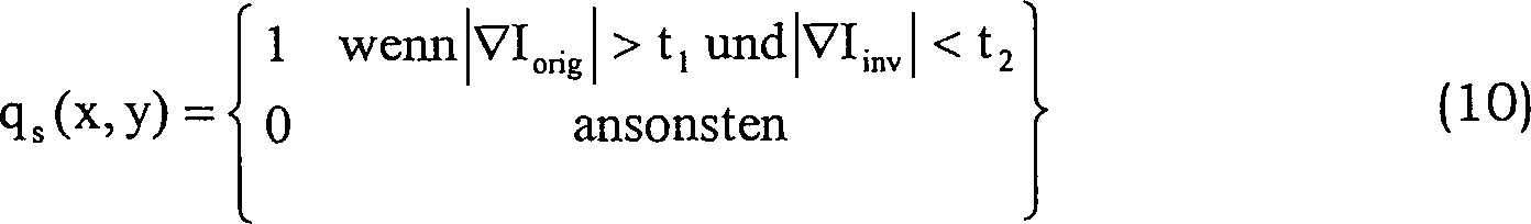
Alternativ kann eine Schattenrandmaskenextraktion durchgeführt werden, indem die Betragsdifferenz der jeweiligen Gradienten verglichen wird. Es wird ein Gradientenbetrag aus dem Eingangsbild ermittelt, und es wird ein Gradientenbetrag aus dem beleuchtungsinvarianten Bildbereich ermittelt. Es wird eine Gradientendifferenz berechnet, indem der Gradientenbetrag des beleuchtungsinvarianten Bildbereichs von dem Gradientenbetrag des Eingangsbilds subtrahiert wird. Die Gradientendifferenz wird mit einem Schwellenwert verglichen, um zu ermitteln, ob ein Schattenrand vorliegt.Alternatively, shadow edge mask extraction may be performed by comparing the magnitude difference of the respective gradients. A gradient amount is determined from the input image, and a gradient amount is determined from the illumination-invariant image area. A gradient difference is calculated by subtracting the gradient amount of the illumination-invariant image area from the gradient amount of the input image. The gradient difference is compared to a threshold to determine if there is a shadow border.
Eine Anfangsschattenrandmaske, die zuerst erzeugt wird, ist in der Hinsicht unvollständig, dass die Randmaske eine Anzahl von falschen Rändern enthält. Folglich wird ein Satz von morphologischen Operationen (z. B. Schließ- und Dilatationsoperationen) verwendet, um die Schattenränder zu verfeinern, um eine schließliche Schattenrandmaske zu erzeugen.An initial shadow border mask that is generated first is incomplete in that the border mask contains a number of false edges. Thus, a set of morphological operations (eg, closure and dilation operations) are used to refine the shadow borders to produce a final shadow edge mask.
Der zweite Schritt umfasst das Anwenden einer schattenreduzierten Bildintegration. Da die Schattenränder an Gradienten der sich ändernden Beleuchtung entsprechen, können die Schattenränder bei den Gradienten des ursprünglichen Bilds durch Anwendung des Schwellenwertverfahrens entfernt werden, wobei die Schattenrandmaske wie oben beschrieben verwendet wird, um die Beleuchtungsauswirkungen zu reduzieren. Folglich liefern die Schwellenwertgradienten die Graustufendarstellung eines Kanals, die ein schattenreduziertes Bild umfasst. Das schließliche vollfarbige schattenreduzierte Bild wird durch Kombinieren aller schattenreduzierten RGB-Kanalgraustufenbilder wiederhergestellt. Um diesen Schritt durchzuführen, werden die Schatten bei dem Gradienten des ursprünglichen Bilds unter Verwendung der Schwellenwertfunktion Ts entfernt.The second step involves applying a shadow-reduced image integration. Since the shadow edges correspond to gradients of the changing illumination, the shadow edges at the gradients of the original image can be removed by applying the thresholding method using the shadow edge mask as described above to reduce the illumination effects. Thus, the threshold gradients provide the grayscale representation of a channel that includes a shadow-reduced image. The final full-color shadow-reduced image is restored by combining all shadow-reduced RGB channel gray-scale images. To perform this step, the shadows at the gradient of the original image are removed using the threshold function T s .

Wenn ein Schattenrand identifiziert wird, werden die Gradienten in dem ursprünglichen Bild auf Null gesetzt, was angibt, dass an dieser Stelle keine Beleuchtungsänderung stattfindet. Nach dem Anwenden des Schwellenwertverfahrens werden die Gradienten nur an den Stellen erhalten, an denen aufgrund der Materialänderungen starke Änderungen vorliegen. Nun wird der Gradient integriert, um ein schattenreduziertes Bild I' wiederherzustellen, das keinen Schatten aufweist. Um dies zu erreichen, wird zur Problemformulierung eine Poisson-Gleichung verwendet, wie folgt:
Auf der linken Seite von Gleichung (13) wird der Laplace-Operator des Bilds wie folgt dargestellt: 
Auf der rechten Seite von Gleichung (13) wird die Formel wie folgt dargestellt: 
Daher wird die Poisson-Gleichung mit homogenen Neumann-Grenzenbedingungen derart aufgelöst, dass die Gradienten an der Grenze auf Null gesetzt werden. Das separate Auflösen der obigen Gleichungen für jeden der drei Farbkanäle leitet ein beispielhaftes rekonstruiertes Graustufenbild für jeden Kanal mit einigen unbekannten multiplikativen Konstanten ab. Das Kombinieren von I' aller RGB-Kanäle erzeugt ein Farbbild, bei dem die Schatten entfernt sind. Ferner wird, um die unbekannten multiplikativen Faktoren zu berichtigen und realistischere Bildfarben zu erhalten, eine Abbildung auf jedes Pixel angewandt, die die hellsten Pixel (z. B. der Mittelwert der oberen 5% von Pixeln geordnet nach Intensität) in dem wiederhergestellten Bild auf die entsprechenden Pixel in dem ursprünglichen Bild abbildet. In der Praxis wird jedem Pixel ein Projektionswert zugeordnet, nachdem ein Pixel auf die beleuchtungsinvariante Achse projiziert wurde.Therefore, the Poisson equation with homogeneous Neumann boundary conditions is resolved such that the gradients at the boundary are set to zero. The separate resolution of the above equations for each of the three color channels derives an exemplary reconstructed grayscale image for each channel with some unknown multiplicative constants. Combining I 'of all RGB channels produces a color image with the shadows removed. Further, to correct for the unknown multiplier factors and to obtain more realistic image colors, an image is applied to each pixel having the brightest pixels (eg, the average of the upper 5% of pixels ordered by intensity) in the reconstructed image corresponding pixels in the original image. In practice, each pixel is assigned a projection value after a pixel has been projected onto the illumination invariant axis.
Der oben beschriebene Prozess entfernt erfolgreich Schatten, wenn eine Bildgebungseinrichtung mit hoher Qualität verwendet wird. Wenn man jedoch die Kosten des Einbeziehens einer Bildgebungseinrichtung mit hoher Qualität in ein Fahrzeug in Betracht zieht, ist ein wahrscheinlicheres Szenario die Verwendung einer kostengünstigen Serienkamera für eine Objektdetektion und -klassifizierung. Das Problem ist, dass die kostengünstige Serienkamera der Schmalbandannahme nicht entspricht, da die kostengünstige Serienkamera eine Divergenz bei den Log-Chromatizität-Geraden bewirkt. Ferner ist es unmöglich, das invariante Bild zu bestimmen, da keine invariante Richtung gefunden werden kann. Die folgenden Absätze beschreiben Prozesse zum Anpassen der kostengünstigen Serienkamera, um das Leistungsvermögen einer Schattenentfernung für eine Objektdetektion und -klassifizierung zu verbessern.The process described above successfully removes shadows when using a high quality imaging device. However, considering the cost of incorporating a high quality imaging device into a vehicle, a more likely scenario is the use of a low cost serial camera for object detection and classification. The problem is that the low cost serial camera does not conform to the narrowband assumption because the low cost serial camera divergences the log chromaticity lines. Furthermore, it is impossible to determine the invariant image because no invariant direction can be found. The following paragraphs describe processes for adjusting the low-cost serial camera to improve the performance of shadow removal for object detection and classification.
In den vorherigen Absätzen projizierte der Schattenentfernungsansatz die Log-Chromatizität-Werte verschiedener Farbsätze auf einen linearen Raum, um die Varianz in jedem projizierten Farbsatz unter verschiedenen Beleuchtungsbedingungen zu minimieren. Wie in
Nach dem Projizieren der Farbchromatizitätswerte auf die Beleuchtungsinvarianzachse und dem Darstellen eines Bilds in dem beleuchtungsinvarianten Bildbereich wird ein Gradient der Ränder in dem beleuchtungsinvarianten Bildbereich durch einen Operator berechnet, der einen Sobel-Operator umfasst, jedoch nicht darauf beschränkt ist. Ferner wird ein Gradient des Eingangsbilds durch den Sobel-Operator erhalten.After projecting the color chromaticity values onto the illumination invariance axis and displaying an image in the illumination invariant image area, a gradient of the edges in the illumination invariant image area is calculated by an operator including, but not limited to, a Sobel operator. Further, a gradient of the input image is obtained by the Sobel operator.
Es wird ein Gradientendifferenzbild (d. h. die Gradientendifferenz zwischen dem Gradienten des Eingangsbilds und dem Gradienten des beleuchtungsinvarianten Bildbereichs) berechnet, indem ein Gradientenbetrag des beleuchtungsinvarianten Bildbereichs von einem Gradientenbetrag des Eingangsbilds subtrahiert wird. Auf das Gradientendifferenzbild wird das Schwellenwertverfahren angewandt, um die Schattenrandabbildung zu erzeugen. Für jeden Gradientendifferenzwert wird, wenn der jeweilige Wert größer als ein vorbestimmter Schwellenwert ist, angenommen, dass es sich um einen Schattenrand handelt. Nach dem Entfernen des Schattenrands von dem Gradienten des Eingangsbilds in den RGB-Farbkanälen werden aktualisierte Gradienten erneut in das Farbbild jedes Farbkanals integriert und als schattenreduziertes Bild kombiniert. Folglich kann der Schattenrand leicht erhalten werden, indem eine Konzentration auf einen Farbsatz nur der Fläche des freien Pfads stattfindet.A gradient difference image (ie, the gradient difference between the gradient of the input image and the gradient of the illumination-invariant image area) is calculated by subtracting a gradient amount of the illumination-invariant image area from a gradient amount of the input image. The gradient value image is applied to the gradient difference image to produce the shadow border image. For each gradient difference value, if the respective value is greater than one predetermined threshold, assuming that it is a shadow border. After removing the shadow edge from the gradient of the input image in the RGB color channels, updated gradients are re-integrated into the color image of each color channel and combined as a shadow-reduced image. Consequently, the shadow margin can be easily obtained by focusing on a color set only of the free path area.
In Schritt
In Schritt
In Schritt
In Schritt
In Schritt
In Schritt
In Schritt
In Schritt
In Schritt
In Schritt
In Schritt
In Schritt
Support vector machines (SVMs) umfassen einen Satz von in Beziehung stehenden Lernalgorithmen, die für eine Klassifizierung und Regression verwendet werden. Die Lernalgorithmen sind Trainingsverfahren, die Modelle aufbauen, die verwendet werden, um vorherzusagen, ob ein neuer Abtastwert in eine Kategorie oder eine andere Kategorie fällt. Das SVM-Modell ist eine Darstellung von Kategorien von Punkten in einem Raum, die derart abgebildet werden, dass die separaten Kategorien durch einen deutlichen Zwischenraum geteilt sind. Dann werden neue Abtastwerte auf den gleichen Raum abgebildet, und auf der Grundlage davon, auf welcher Seite des Zwischenraums sie sich befinden, wird vorhergesagt, dass sie zu einer Kategorie gehören. Ferner konstruiert die SVM eine Hyperebene oder einen Satz von Hyperebenen in einem Raum mit hoher Dimensionalität, was für eine Klassifizierung, Regression oder andere Aufgaben verwendet werden kann. Es ist eine gute Trennung durch die Hyperebene erwünscht, die die größte räumliche Distanz zu den naheliegendsten Trainingsdatenpunkten jeder Klasse aufweist. Je größer die räumliche Trennungsdistanz ist, desto geringer sind die Generalisierungsfehler des Klassifizierers.Support vector machines (SVMs) comprise a set of related learning algorithms used for classification and regression. The learning algorithms are training methods that build models that are used to predict whether a new sample falls into a category or another category. The SVM model is a representation of categories of points in a room that are mapped such that the separate categories are divided by a significant gap. Then new samples are mapped to the same space and predicted to belong to a category based on which side of the space they are on. Further, the SVM constructs a hyperplane or a set of hyperplanes in a high dimensionality space, which can be used for classification, regression, or other tasks. It is desirable to have a good separation through the hyperplane that has the greatest spatial distance to the nearest training data points of each class. The greater the spatial separation distance, the lower the classification error of the classifier.
Das Flussdiagramm, wie es in
Während bestimmte Ausführungsformen der vorliegenden Erfindung ausführlich beschrieben wurden, werden Fachleute, die diese Erfindung betrifft, verschiedene alternative Entwürfe und Ausführungsformen zum Ausführen der Erfindung wie durch die folgenden Ansprüche definiert erkennen.While particular embodiments of the present invention have been described in detail, those skilled in the art to which this invention relates will recognize various alternative designs and embodiments for carrying out the invention as defined by the following claims.
Claims (7)
Applications Claiming Priority (2)
| Application Number | Priority Date | Filing Date | Title |
|---|---|---|---|
| US12/830,525 | 2010-07-06 | ||
| US12/830,525 US8294794B2 (en) | 2010-07-06 | 2010-07-06 | Shadow removal in an image captured by a vehicle-based camera for clear path detection |
Publications (2)
| Publication Number | Publication Date |
|---|---|
| DE102011106050A1 DE102011106050A1 (en) | 2012-01-12 |
| DE102011106050B4 true DE102011106050B4 (en) | 2017-11-02 |
Family
ID=45372777
Family Applications (1)
| Application Number | Title | Priority Date | Filing Date |
|---|---|---|---|
| DE102011106050.6A Expired - Fee Related DE102011106050B4 (en) | 2010-07-06 | 2011-06-30 | Shadow removal in an image captured by a vehicle-based camera for detection of a clear path |
Country Status (3)
| Country | Link |
|---|---|
| US (1) | US8294794B2 (en) |
| CN (1) | CN102314600B (en) |
| DE (1) | DE102011106050B4 (en) |
Families Citing this family (36)
| Publication number | Priority date | Publication date | Assignee | Title |
|---|---|---|---|---|
| US8836714B2 (en) * | 2010-10-29 | 2014-09-16 | The University Of Utah Research Foundation | Rapid, interactive editing of massive imagery data |
| US8773535B2 (en) * | 2010-12-08 | 2014-07-08 | GM Global Technology Operations LLC | Adaptation for clear path detection using reliable local model updating |
| US8948449B2 (en) * | 2012-02-06 | 2015-02-03 | GM Global Technology Operations LLC | Selecting visible regions in nighttime images for performing clear path detection |
| US8559727B1 (en) * | 2012-04-09 | 2013-10-15 | GM Global Technology Operations LLC | Temporal coherence in clear path detection |
| CN103455998B (en) * | 2012-06-04 | 2017-12-22 | 中兴通讯股份有限公司 | The detection method and device of shade in video image |
| JP5942771B2 (en) | 2012-10-18 | 2016-06-29 | 富士通株式会社 | Image processing apparatus and image processing method |
| DE102012024874B4 (en) * | 2012-12-19 | 2014-07-10 | Audi Ag | Method and device for predicatively determining a parameter value of a vehicle passable surface |
| CN104156937B (en) * | 2013-05-15 | 2017-08-11 | 株式会社理光 | shadow detection method and device |
| US9430842B1 (en) * | 2013-07-17 | 2016-08-30 | Stc.Unm | Material classification fused with spatio-spectral edge detection in spectral imagery |
| US9070023B2 (en) * | 2013-09-23 | 2015-06-30 | Toyota Motor Engineering & Manufacturing North America, Inc. | System and method of alerting a driver that visual perception of pedestrian may be difficult |
| KR101498975B1 (en) | 2013-11-29 | 2015-03-05 | 현대모비스(주) | Lane Departure Warning System |
| JP2015200976A (en) * | 2014-04-04 | 2015-11-12 | 富士通株式会社 | Movement amount estimation device, movement amount estimation method, and program |
| US9594964B2 (en) | 2014-06-12 | 2017-03-14 | GM Global Technology Operations LLC | Vision-based wet road surface detection using texture analysis |
| US9361527B1 (en) * | 2014-11-17 | 2016-06-07 | Tandent Vision Science, Inc. | Method and system for classifying painted road markings in an automotive driver vehicle-assistance device |
| US9218534B1 (en) * | 2014-11-17 | 2015-12-22 | Tandent Vision Science, Inc. | Method and system for classifying painted road markings in an automotive driver-vehicle-assistance device |
| US9875415B2 (en) * | 2014-11-17 | 2018-01-23 | Tandent Vision Science, Inc. | Method and system for classifying painted road markings in an automotive driver-vehicle-asistance device |
| GB2533581B (en) * | 2014-12-22 | 2016-12-07 | Ibm | Image processing |
| US10281378B2 (en) * | 2016-05-05 | 2019-05-07 | Honeywell Federal Manufacturing & Technologies, Llc | System and method for testing true stress and true strain |
| US10290111B2 (en) * | 2016-07-26 | 2019-05-14 | Qualcomm Incorporated | Systems and methods for compositing images |
| DE102017207438B4 (en) | 2017-05-03 | 2020-07-09 | Volkswagen Aktiengesellschaft | Method, device and its use for determining the articulation angle of a team |
| US10140530B1 (en) * | 2017-08-09 | 2018-11-27 | Wipro Limited | Method and device for identifying path boundary for vehicle navigation |
| WO2019182782A1 (en) * | 2018-03-21 | 2019-09-26 | Zoox, Inc. | Generating maps without shadows |
| US10699477B2 (en) * | 2018-03-21 | 2020-06-30 | Zoox, Inc. | Generating maps without shadows |
| US10504282B2 (en) | 2018-03-21 | 2019-12-10 | Zoox, Inc. | Generating maps without shadows using geometry |
| CN111526263B (en) * | 2019-02-01 | 2022-03-18 | 光宝电子(广州)有限公司 | Image processing method, device and computer system |
| CN110443762B (en) * | 2019-07-24 | 2023-09-22 | 南京末梢信息技术有限公司 | Pavement shadow suppression method |
| JP7310526B2 (en) * | 2019-10-14 | 2023-07-19 | 株式会社デンソー | Obstacle identification device and obstacle identification program |
| US11070707B1 (en) * | 2020-01-06 | 2021-07-20 | GM Global Technology Operations LLC | System and method to remove a vehicle shadow from a video feed |
| CN111612882B (en) * | 2020-06-10 | 2023-04-07 | 腾讯科技(深圳)有限公司 | Image processing method, image processing device, computer storage medium and electronic equipment |
| CN112396507A (en) * | 2020-09-01 | 2021-02-23 | 重庆邮电大学 | Shadow division-based integrated SVM personal credit evaluation method |
| US11776200B2 (en) | 2021-11-10 | 2023-10-03 | Ford Global Technologies, Llc | Image relighting |
| US11756261B2 (en) | 2021-11-10 | 2023-09-12 | Ford Global Technologies, Llc | Single-perspective image relighting |
| DE102022206328B3 (en) | 2022-04-19 | 2023-02-09 | Continental Autonomous Mobility Germany GmbH | Method for a camera system and camera system |
| WO2023202844A1 (en) | 2022-04-19 | 2023-10-26 | Continental Autonomous Mobility Germany GmbH | Method for a camera system, and camera system |
| DE102023101366B3 (en) | 2023-01-20 | 2024-03-21 | Cariad Se | Computer-implemented method, processor circuit and system for determining a marking course of a lane marking of a lane that is currently being traveled by a vehicle |
| CN116883504B (en) * | 2023-09-07 | 2023-12-08 | 深圳魔视智能科技有限公司 | Method and device for calibrating vehicle orientation, computer equipment and storage medium |
Citations (1)
| Publication number | Priority date | Publication date | Assignee | Title |
|---|---|---|---|---|
| US20100097455A1 (en) * | 2008-04-24 | 2010-04-22 | Gm Global Technology Operations, Inc | Clear path detection using a vanishing point |
Family Cites Families (3)
| Publication number | Priority date | Publication date | Assignee | Title |
|---|---|---|---|---|
| EP0669034B1 (en) * | 1992-11-10 | 1997-01-15 | Siemens Aktiengesellschaft | Process for detecting and eliminating the shadow of moving objects in a sequence of digital images |
| CA2135240A1 (en) * | 1993-12-01 | 1995-06-02 | James F. Frazier | Automated license plate locator and reader |
| AU1089300A (en) * | 1999-11-03 | 2001-05-14 | Cet Technologies Pte Ltd | Image processing techniques for a video based traffic monitoring system and methods therefor |
-
2010
- 2010-07-06 US US12/830,525 patent/US8294794B2/en not_active Expired - Fee Related
-
2011
- 2011-06-30 DE DE102011106050.6A patent/DE102011106050B4/en not_active Expired - Fee Related
- 2011-07-06 CN CN201110187745.XA patent/CN102314600B/en not_active Expired - Fee Related
Patent Citations (1)
| Publication number | Priority date | Publication date | Assignee | Title |
|---|---|---|---|---|
| US20100097455A1 (en) * | 2008-04-24 | 2010-04-22 | Gm Global Technology Operations, Inc | Clear path detection using a vanishing point |
Non-Patent Citations (2)
| Title |
|---|
| Álvarez, José; López, Antonio; Baldrich, Ramon: "Shadow Resistant Road Segmentation from a Mobile Monocular System"; Springer Berlin / Heidelberg; 2007; Lecture Notes in Computer Science; Pattern Recognition and Image Analysis; vol. 4478; Seiten 9-16; DOI: 10.1007/978-3-540-72849-8_2 * |
| Finlayson, G., Hordley, S., Lu, C., Drew, M.: "On the removal of shadows from images"; IEEE Trans. on Pattern Analysis and Machine Intelligence; Jan. 2006; vol. 28(1), Seiten 59-68, DOI: 10.1109/TPAMI.2006.18 * |
Also Published As
| Publication number | Publication date |
|---|---|
| US8294794B2 (en) | 2012-10-23 |
| CN102314600A (en) | 2012-01-11 |
| CN102314600B (en) | 2014-05-14 |
| DE102011106050A1 (en) | 2012-01-12 |
| US20120008021A1 (en) | 2012-01-12 |
Similar Documents
| Publication | Publication Date | Title |
|---|---|---|
| DE102011106050B4 (en) | Shadow removal in an image captured by a vehicle-based camera for detection of a clear path | |
| DE102011106052B4 (en) | Shadow removal in an image captured by a vehicle based camera using a nonlinear illumination invariant core | |
| DE102011106072A1 (en) | SHADOW REMOVAL IN A PICTURE BASED ON A VEHICLE-BASED CAMERA USING AN OPTIMIZED LINEAR AXIS | |
| DE102013205950B4 (en) | Roadside detection method | |
| DE112012002885B4 (en) | Method and device for image-based vehicle detection and distance measurement | |
| DE102011086512B4 (en) | fog detection | |
| EP3014569B1 (en) | Inspection of the contoured surface of the underbody of a motor vehicle | |
| DE102016118502A1 (en) | Method, device and device for determining a roadway boundary | |
| DE102012222497A1 (en) | System and method for detecting parking space markings for vehicles | |
| EP3183721A1 (en) | Method and axle-counting device for contact-free axle counting of a vehicle and axle-counting system for road traffic | |
| DE112011103690T5 (en) | Detection and tracking of moving objects | |
| DE112013001858T5 (en) | Multiple-hint object recognition and analysis | |
| DE112009000949T5 (en) | Detection of a free driving path for a vehicle | |
| DE102006005512A1 (en) | System and method for measuring the distance of a preceding vehicle | |
| DE102013205854B4 (en) | Method for detecting a free path using temporary coherence | |
| DE102014112820A9 (en) | Vehicle exterior environment recognition device | |
| DE102014117102A1 (en) | Lane change warning system and method for controlling the lane change warning system | |
| DE102013204597A1 (en) | Method and apparatus for determining visibility in fog during the day | |
| DE102014208271A1 (en) | Method and apparatus for image based vision estimation | |
| DE102015207902A1 (en) | Method and device for confirming the relevant inner white circle in the recognition of the environment of a circular traffic sign | |
| DE102014012653A1 (en) | Image processing method for vehicle camera and this image processing apparatus | |
| EP2546778A2 (en) | Method for evaluating an object detection device of a motor vehicle | |
| DE112020004301T5 (en) | OBJECT RECOGNITION DEVICE | |
| DE112015006662T5 (en) | DISPLAY CONTROL DEVICE, DISPLAY CONTROL METHOD AND DISPLAY CONTROL PROGRAM | |
| DE102018100909A1 (en) | Method of reconstructing images of a scene taken by a multifocal camera system |
Legal Events
| Date | Code | Title | Description |
|---|---|---|---|
| R012 | Request for examination validly filed | ||
| R016 | Response to examination communication | ||
| R002 | Refusal decision in examination/registration proceedings | ||
| R006 | Appeal filed | ||
| R008 | Case pending at federal patent court | ||
| R019 | Grant decision by federal patent court | ||
| R020 | Patent grant now final | ||
| R119 | Application deemed withdrawn, or ip right lapsed, due to non-payment of renewal fee |