DE102011054586A1 - Sealing arrangement for a turbomachine - Google Patents
Sealing arrangement for a turbomachine Download PDFInfo
- Publication number
- DE102011054586A1 DE102011054586A1 DE102011054586A DE102011054586A DE102011054586A1 DE 102011054586 A1 DE102011054586 A1 DE 102011054586A1 DE 102011054586 A DE102011054586 A DE 102011054586A DE 102011054586 A DE102011054586 A DE 102011054586A DE 102011054586 A1 DE102011054586 A1 DE 102011054586A1
- Authority
- DE
- Germany
- Prior art keywords
- turbomachine
- channel
- sealing
- sealing arrangement
- section
- Prior art date
- Legal status (The legal status is an assumption and is not a legal conclusion. Google has not performed a legal analysis and makes no representation as to the accuracy of the status listed.)
- Withdrawn
Links
Images


Classifications
-
- F—MECHANICAL ENGINEERING; LIGHTING; HEATING; WEAPONS; BLASTING
- F01—MACHINES OR ENGINES IN GENERAL; ENGINE PLANTS IN GENERAL; STEAM ENGINES
- F01D—NON-POSITIVE DISPLACEMENT MACHINES OR ENGINES, e.g. STEAM TURBINES
- F01D11/00—Preventing or minimising internal leakage of working-fluid, e.g. between stages
- F01D11/08—Preventing or minimising internal leakage of working-fluid, e.g. between stages for sealing space between rotor blade tips and stator
- F01D11/12—Preventing or minimising internal leakage of working-fluid, e.g. between stages for sealing space between rotor blade tips and stator using a rubstrip, e.g. erodible. deformable or resiliently-biased part
- F01D11/122—Preventing or minimising internal leakage of working-fluid, e.g. between stages for sealing space between rotor blade tips and stator using a rubstrip, e.g. erodible. deformable or resiliently-biased part with erodable or abradable material
-
- F—MECHANICAL ENGINEERING; LIGHTING; HEATING; WEAPONS; BLASTING
- F01—MACHINES OR ENGINES IN GENERAL; ENGINE PLANTS IN GENERAL; STEAM ENGINES
- F01D—NON-POSITIVE DISPLACEMENT MACHINES OR ENGINES, e.g. STEAM TURBINES
- F01D11/00—Preventing or minimising internal leakage of working-fluid, e.g. between stages
- F01D11/001—Preventing or minimising internal leakage of working-fluid, e.g. between stages for sealing space between stator blade and rotor
-
- F—MECHANICAL ENGINEERING; LIGHTING; HEATING; WEAPONS; BLASTING
- F01—MACHINES OR ENGINES IN GENERAL; ENGINE PLANTS IN GENERAL; STEAM ENGINES
- F01D—NON-POSITIVE DISPLACEMENT MACHINES OR ENGINES, e.g. STEAM TURBINES
- F01D9/00—Stators
- F01D9/02—Nozzles; Nozzle boxes; Stator blades; Guide conduits, e.g. individual nozzles
Abstract
Eine Dichtungsanordnung (60, 62, 181) einer Turbomaschine (2) enthält mehrere Dichtleisten (80, 81, 82, 83, 183, 184, 185, 200), die konfiguriert und angeordnet sind, um eine Fluidströmung am Hindurchtreten durch einen Kanal (38, 40), der durch ein erstes Element und ein zweites Element definiert ist, zu hindern. Wenigstens eine der mehreren Dichtleisten (80, 81, 82, 83, 183, 184, 185, 200) enthält ein Schaufelelement (124, 144, 154, 160, 187, 188, 189, 234), das konfiguriert und angeordnet ist, um eine Fluidrezirkulationszone an dem Kanal (38, 40) zu schaffen. Die Fluidrezirkulationszone behindert weiter den Fluidfluss durch den Kanal (38, 40).A sealing arrangement (60, 62, 181) of a turbomachine (2) includes a plurality of sealing strips (80, 81, 82, 83, 183, 184, 185, 200) which are configured and arranged to prevent fluid flow from passing through a channel ( 38, 40), which is defined by a first element and a second element. At least one of the plurality of sealing strips (80, 81, 82, 83, 183, 184, 185, 200) includes a vane element (124, 144, 154, 160, 187, 188, 189, 234) that is configured and arranged to create a fluid recirculation zone on the channel (38, 40). The fluid recirculation zone further impedes fluid flow through the channel (38, 40).
Description
HINTERGRUND ZU DER ERFINDUNGBACKGROUND TO THE INVENTION
Der hierin offenbarte Gegenstand betrifft das Gebiet von Turbomaschinen und insbesondere eine Dichtungsanordnung, die eine Fluidströmung in einer Turbomaschine behindert.The subject matter disclosed herein relates to the field of turbomachinery and, more particularly, to a seal assembly that obstructs fluid flow in a turbomachine.
In einer typischen Gasturbinenmaschine empfangen Brennkammern zugeführte Druckluft von einem Verdichterabschnitt und zugeführten Brennstoff. Die Druckluft und der Brennstoff werden miteinander vermischt, um ein brennbares Luft/Brennstoff-Gemisch zu bilden. Das Luft/Brennstoff-Gemisch wird anschließend gezündet und verbrannt, um heiße Gase zu erzeugen, die in einen Turbinenabschnitt geleitet werden. Thermische Energie aus den Heißgasen wird in mechanische Rotationsenergie in dem Turbinenabschnitt umgewandelt.In a typical gas turbine engine, combustors receive pressurized air from a compressor section and supplied fuel. The compressed air and the fuel are mixed together to form a combustible air / fuel mixture. The air / fuel mixture is then ignited and burned to produce hot gases that are directed into a turbine section. Thermal energy from the hot gases is converted to mechanical rotational energy in the turbine section.
Die Heißgase werden aus der Brennkammer in den Turbinenabschnitt durch einen Übergangskanal oder ein Übergangsstück geleitet. Im Allgemeinen umgibt ein Luftkanal, der Kühlluft von dem Verdichter liefert, das Übergangsstück. Wenn die inneren Flächen nicht richtig abgedichtet sind, können die Heißgase den Turbinenabschnitt umströmen und in den Luftkanal eintreten. Diese Bypass- oder Leckageströmung verrichtet keine Arbeit und stellt somit innere Verluste in der Turbomaschine dar. Die Leckageströmung tritt im Allgemeinen zwischen benachbarten Flächen hindurch, die sich mit variablen Drehzahlen bewegen oder drehen. Mit der Zeit können die Spiele zwischen den Flächen variabler Drehzahl aufgrund eines inneren Reibens, einer Erosion durch Festpartikel, einer Beschädigung durch Fremdobjekte und dergleichen steigen. Derzeit verwenden viele Turbomaschinen Labyrinthdichtungen zwischen den Flächen mit variabler Drehzahl, um die Leckageströmung zu begrenzen. Die Labyrinthdichtungen erzeugen mehrere Barrieren, die die Heißgase deutlich daran beschränken, in die Kühlluftströmung in dem Luftkanal einzutreten.The hot gases are directed from the combustor into the turbine section through a transition duct or transition piece. Generally, an air passage that supplies cooling air from the compressor surrounds the transition piece. If the inner surfaces are not properly sealed, the hot gases may bypass the turbine section and enter the air duct. This bypass or leakage flow does no work and thus constitutes internal losses in the turbomachine. Leakage flow generally occurs between adjacent surfaces that move or rotate at variable speeds. Over time, the clearance between the variable speed surfaces may increase due to internal friction, erosion by solid particles, damage by foreign objects, and the like. Currently, many turbomachines use labyrinth seals between the variable speed surfaces to limit the leakage flow. The labyrinth seals create multiple barriers that significantly restrict the hot gases from entering the cooling air flow in the air channel.
KURZE BESCHREIBUNG DER ERFINGUNGBRIEF DESCRIPTION OF THE INVENTION
Gemäß einem Aspekt der Erfindung enthält eine Turbomaschinendichtungsanordnung mehrere Dichtleisten, die konfiguriert und angeordnet sind, um eine Fluidströmung daran zu hindern, durch einen Kanal hindurchzutreten, der durch ein erstes Element und ein zweites Element gebildet ist. Wenigstens eine der mehreren Dichtleisten enthält ein Flügel- bzw. Schaufelelement, das konfiguriert und angeordnet ist, um eine Fluidrezirkulationszone an dem Kanal zu erzeugen. Die Fluidrezirkulationszone behindert weiter den Fluidfluss durch den Kanal.In accordance with one aspect of the invention, a turbomachine seal assembly includes a plurality of sealing strips that are configured and arranged to prevent fluid flow from passing through a channel formed by a first member and a second member. At least one of the plurality of sealing strips includes a vane member configured and arranged to create a fluid recirculation zone on the channel. The fluid recirculation zone further impedes fluid flow through the channel.
Gemäß einem weiteren Aspekt der Erfindung enthält eine Turbomaschine ein erstes Element, ein zweites Element, das in der Nähe des ersten Elementes angeordnet ist, einen Kanal, der sich zwischen dem ersten Element und dem zweiten Element erstreckt und durch diese gebildet ist, und eine Dichtungsanordnung, die an einem von dem ersten Element und dem zweiten Element in dem Kanal montiert ist. Die Dichtungsanordnung enthält mehrere Dichtleisten, die sich zu dem anderen von dem ersten Element und dem zweiten Element hin erstrecken. Die mehreren Dichtleisten hindern eine Fluidströmung am Hindurchtreten durch den Kanal. Wenigstens eine der mehreren Dichtleisten enthält ein Schaufelelement, das konfiguriert und angeordnet ist, um eine Fluidrezirkulationszone an dem Kanal zu erzeugen. Die Fluidrezirkulationszone unterdrückt weiter den Fluiddurchfluss durch den Kanal.In accordance with another aspect of the invention, a turbomachine includes a first member, a second member disposed proximate the first member, a channel extending between and formed by the first member and the second member, and a seal assembly mounted on one of the first member and the second member in the channel. The seal assembly includes a plurality of sealing strips extending toward the other of the first member and the second member. The plurality of sealing strips prevent fluid flow from passing through the channel. At least one of the plurality of sealing strips includes a vane member configured and arranged to create a fluid recirculation zone on the channel. The fluid recirculation zone further suppresses fluid flow through the channel.
Diese und weitere Vorteile und Merkmale werden aus der folgenden Beschreibung in Verbindung mit den Zeichnungen offenkundiger.These and other advantages and features will become more apparent from the following description taken in conjunction with the drawings.
KURZE BESCHREIBUNG DER ZEICHNUNGBRIEF DESCRIPTION OF THE DRAWING
Der Gegenstand, der als die Erfindung angesehen wird, ist in den Ansprüchen am Schluss der Beschreibung besonders angegeben und deutlich beansprucht. Das Vorstehende und weitere Merkmale sowie Vorteile der Erfindung werden aus der folgenden detaillierten Beschreibung in Verbindung mit den beigefügten Zeichnungen offensichtlich, in denen zeigen:The subject matter considered to be the invention is particularly pointed out and distinctly claimed in the claims at the conclusion of the specification. The foregoing and other features and advantages of the invention will be apparent from the following detailed description, taken in conjunction with the accompanying drawings, in which:
Die detaillierte Beschreibung erläutert Ausführungsformen der Erfindung gemeinsam mit Vorteilen und Merkmalen anhand eines Beispiels unter Bezugnahme auf die Zeichnungen.The detailed description explains embodiments of the invention together with advantages and features by way of example with reference to the drawings.
DETAILLIERTE BESCHREIBUNG DER ERFINDUNGDETAILED DESCRIPTION OF THE INVENTION
Die Ausdrücke „axial” und „in Axialrichtung”, wie sie in dieser Anmeldung verwendet werden, bezeichnen Richtungen und Orientierungen, die im Wesentlichen parallel zu einer Längs- und Mittelachse einer Turbomaschine verlaufen. Die Ausdrücke „radial” und „in Radialrichtung”, wie sie in dieser Anmeldung verwendet werden, beziehen sich auf Richtungen und Orientierungen, die im Wesentlichen senkrecht zu der Mittel- und Längsachse der Turbomaschine verlaufen. Die Ausdrücke „stromaufwärts” und „stromabwärts”, wie sie in dieser Anmeldung verwendet werden, beziehen sich auf Richtungen und Orientierungen relativ zu einer axialen Strömungsrichtung in Bezug auf die Mittel- und Längsachse der Turbomaschine.The terms "axial" and "axial" as used in this application refer to directions and orientations that are substantially parallel to a longitudinal and a central axis of a turbomachine. The terms "radial" and "radial" as used in this application refer to directions and orientations that are substantially perpendicular to the central and longitudinal axes of the turbomachine. The terms "upstream" and "downstream" as used in this application refer to directions and orientations relative to an axial flow direction with respect to the center and longitudinal axes of the turbomachine.
Unter Bezugnahme auf
An dieser Stelle sollte erkannt werden, dass die Anzahl von Stufen, die in dem Turbinenabschnitt
Da jede Dichtungsanordnung
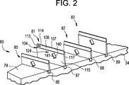
Wie am besten in
Es wird nun auf
Es wird nun auf die
An dieser Stelle sollte verstanden werden, dass die beispielhaften Ausführungsformen eine Dichtungsanordnung ergeben, die konfiguriert ist, um eine Fluidströmung in einer Turbinenmaschine zwischen bewegbaren Flächen zu verhindern. Die Dichtungsanordnung verhindert eine Fluidströmung durch Erzeugung einer Querstrom- oder Rezirkulationszone an einer oder mehreren Dichtleisten. Die Rezirkulationszone erzeugt eine Barriere an den Spitzenabschnitten der Dichtleisten, die einen Fluidfluss weiter unterbindet. Es sollte ferner erkannt werden, dass, während die Dichtungsanordnung zwischen einem Abstandshalter (einem stationären Element) und einer Schaufel (einem bewegenden Element) angeordnet veranschaulicht ist, die Dichtungsanordnung gemäß der beispielhaften Ausführungsform an Stellen zwischen Oberflächen mit variabler Drehzahl eingebaut sein kann. Ferner kann, obwohl sie veranschaulicht ist, wie sie als eine Packungsdichtung zwischen mit variabler Drehzahl relativ zueinander umlaufenden Flächen wirkt, die Dichtungsanordnung gemäß der beispielhaften Ausführungsform auch dazu verwendet werden, eine Strömung zwischen verschiedenen anderen bewegbaren Flächen, einschließlich Flächen, die sich translatorisch bewegen lassen, Flächen, die sich relativ zu einem stationären Element bewegen lassen, oder Flächen, die mit im Wesentlichen ähnlichen Drehzahlen umlaufen, eingesetzt werden. D. h., die Dichtungsanordnung kann an vielfältigen Stellen eingebaut werden, wozu auch die Verendung als Laufschaufeldichtungen und Zwischenstufendichtungen gehören. Es sollte ferner verstanden werden, dass die Dichtungsanordnung in einem breiten Spektrum von Turbomaschinenmodellen, einschließlich Gasturbinenmaschinen und Dampfturbinenmaschinen, eingebaut werden kann.At this point, it should be understood that the exemplary embodiments provide a seal assembly that is configured to prevent fluid flow in a turbine engine between movable surfaces. The seal arrangement prevents fluid flow by creating a cross-flow or recirculation zone on one or more sealing strips. The recirculation zone creates a barrier at the tip portions of the sealing strips which further inhibits fluid flow. It should also be appreciated that while the seal assembly is illustrated as being disposed between a spacer (a stationary member) and a blade (a moving member), the seal assembly according to the exemplary embodiment may be installed at locations between variable speed surfaces. Further, while illustrated as acting as a packing seal between variable speed rotating surfaces relative to each other, the seal assembly of the exemplary embodiment may also be used to facilitate flow between various other movable surfaces, including surfaces that translate , Surfaces that move relative to a stationary element, or surfaces that rotate at substantially similar speeds are used. D. h., The seal assembly can be installed in a variety of places, including the use as a blade seals and interstage seals. It should be further understood that the seal assembly may be incorporated in a wide variety of turbomachinery models, including gas turbine engines and steam turbine engines.
Während die Erfindung im Einzelnen in Verbindung mit lediglich einer begrenzten Anzahl von Ausführungsformen beschrieben worden ist, sollte ohne weiteres verstanden werden, dass die Erfindung nicht auf derartige offenbarte Ausführungsformen beschränkt ist. Vielmehr kann die Erfindung modifiziert werden, um eine beliebige Anzahl von Veränderungen, Modifizierungen, Ersetzungen oder äquivalenten Anordnungen aufzunehmen, die hier vorstehend nicht beschrieben sind, die jedoch dem Rahmen und Umfang der Erfindung entsprechen. Außerdem ist es zu verstehen, dass, während verschiedene Ausführungsformen der Erfindung beschrieben worden sind, Aspekte der Erfindung lediglich einige von den beschriebenen Ausführungsformen enthalten können. Demgemäß ist die Erfindung nicht als durch die vorstehende Beschreibung beschränkt anzusehen, sondern ist nur durch den Umfang der beigefügten Ansprüche beschränkt.While the invention has been described in detail in connection with only a limited number of embodiments, it should be readily understood that the invention is not limited to such disclosed embodiments. Rather, the invention may be modified to incorporate any number of variations, modifications, substitutions, or equivalent arrangements not heretofore described, which, however, are within the spirit and scope of the invention. Additionally, it should be understood that while various embodiments of the invention have been described, aspects of the invention may only include some of the described embodiments. Accordingly, the invention should not be construed as being limited to the foregoing description, but is limited only by the scope of the appended claims.
Eine Dichtungsanordnung
BezugszeichenlisteLIST OF REFERENCE NUMBERS
- 22
- Turbomaschineturbomachinery
- 1010
- Turbinenabschnittturbine section
- 1212
- ÜbergangsstückTransition piece
- 1616
- Laufschaufeln der ersten StufeRotor blades of the first stage
- 1818
- Laufrad der ersten StufeImpeller of the first stage
- 2020
- Leitschaufeln der ersten StufeVanes of the first stage
- 21, 27, 3321, 27, 33
- TurbinengehäuseelementTurbine housing element
- 2222
- Laufschaufeln der zweiten StufeBlades of the second stage
- 2424
- LaufradWheel
- 2626
- Leitschaufeln der zweiten StufeGuide vanes of the second stage
- 2828
- Laufschaufeln der dritten StufeBlades of the third stage
- 3030
- Laufrad der dritten StufeImpeller of the third stage
- 3232
- Leitschaufeln der dritten StufeThird stage vanes
- 34, 3634, 36
- Abstandshalterspacer
- 38, 4038, 40
- Kanalchannel
- 43, 22843, 228
- Bereich (Verdichteraustritt)Range (compressor outlet)
- 60, 62, 18160, 62, 181
- Dichtungsanordnungsealing arrangement
- 7474
- Oberflächesurface
- 80, 81, 82, 83, 183, 184, 185, 20080, 81, 82, 83, 183, 184, 185, 200
- Dichtleistesealing strip
- 86, 87, 88, 8986, 87, 88, 89
- Nutgroove
- 94, 95, 96, 9794, 95, 96, 97
- Dichtungsdrahtsealing wire
- 104, 204104, 204
- Hauptkörpermain body
- 106106
- erstes Ende/Schwanzendefirst end / tail end
- 107107
- zweites Ende/auskragendes Endesecond end / cantilever end
- 108108
- Zwischenabschnittintermediate section
- 109, 197, 198, 199109, 197, 198, 199
- vertiefter Bereichrecessed area
- 110, 228110, 228
- Oberflächesurface
- 111111
- erste Dickefirst thickness
- 113, 220113, 220
- Bereich mit reduzierter DickeArea with reduced thickness
- 114, 225114, 225
- Spitzenabschnitttip portion
- 115, 210115, 210
- stromaufwärtige Flächeupstream surface
- 117, 212117, 212
- stromabwärtige Flächedownstream area
- 124, 144, 154, 160, 187, 188, 189, 234124, 144, 154, 160, 187, 188, 189, 234
- Schaufelelementvane element
- 140, 146, 164140, 146, 164
- erste Flächefirst surface
- 141, 147, 165141, 147, 165
- zweite Flächesecond surface
- 156, 162156, 162
- gekrümmte Oberflächecurved surface
- 166166
- Tragflächenprofilairfoil
- 194, 195, 196194, 195, 196
- Vorsprüngeprojections
- 206206
- erstes Endefirst end
- 208208
- zweites Endesecond end
- 218218
- Abschnittsection
- 222, 226222, 226
- Schwanzbereichtail region
Claims (9)
Applications Claiming Priority (2)
| Application Number | Priority Date | Filing Date | Title |
|---|---|---|---|
| US12/906,585 | 2010-10-18 | ||
| US12/906,585 US8591181B2 (en) | 2010-10-18 | 2010-10-18 | Turbomachine seal assembly |
Publications (1)
| Publication Number | Publication Date |
|---|---|
| DE102011054586A1 true DE102011054586A1 (en) | 2012-04-19 |
Family
ID=45895946
Family Applications (1)
| Application Number | Title | Priority Date | Filing Date |
|---|---|---|---|
| DE102011054586A Withdrawn DE102011054586A1 (en) | 2010-10-18 | 2011-10-18 | Sealing arrangement for a turbomachine |
Country Status (5)
| Country | Link |
|---|---|
| US (1) | US8591181B2 (en) |
| JP (1) | JP5879084B2 (en) |
| DE (1) | DE102011054586A1 (en) |
| FR (1) | FR2966195B1 (en) |
| RU (1) | RU2011142880A (en) |
Families Citing this family (14)
| Publication number | Priority date | Publication date | Assignee | Title |
|---|---|---|---|---|
| US8591181B2 (en) | 2010-10-18 | 2013-11-26 | General Electric Company | Turbomachine seal assembly |
| GB2492546A (en) * | 2011-07-04 | 2013-01-09 | Alstom Technology Ltd | A labyrinth seal for an axial fluid flow turbomachine |
| GB201207837D0 (en) * | 2012-05-04 | 2012-06-20 | Rolls Royce Plc | Leaf seal |
| US20140054863A1 (en) * | 2012-08-21 | 2014-02-27 | General Electric Company | Seal assembly for a turbine system |
| JP5951449B2 (en) * | 2012-11-02 | 2016-07-13 | 株式会社東芝 | Steam turbine |
| GB201311610D0 (en) * | 2013-06-28 | 2013-08-14 | Rolls Royce Plc | A Leaf Seal |
| GB201311611D0 (en) | 2013-06-28 | 2013-08-14 | Rolls Royce Plc | A Brush Seal |
| GB201311607D0 (en) | 2013-06-28 | 2013-08-14 | Rolls Royce Plc | A leaf seal |
| US9506366B2 (en) | 2013-08-06 | 2016-11-29 | General Electric Company | Helical seal system for a turbomachine |
| EP2949871B1 (en) * | 2014-05-07 | 2017-03-01 | United Technologies Corporation | Variable vane segment |
| JP6167158B2 (en) * | 2015-12-09 | 2017-07-19 | 三菱日立パワーシステムズ株式会社 | Seal structure and turbomachine |
| JP6662661B2 (en) * | 2016-02-29 | 2020-03-11 | 三菱日立パワーシステムズ株式会社 | Seal structure and turbo machinery |
| FR3053386B1 (en) * | 2016-06-29 | 2020-03-20 | Safran Helicopter Engines | TURBINE WHEEL |
| JP7211877B2 (en) * | 2019-04-11 | 2023-01-24 | 三菱重工業株式会社 | Steam turbine rotor and steam turbine |
Family Cites Families (27)
| Publication number | Priority date | Publication date | Assignee | Title |
|---|---|---|---|---|
| US1831242A (en) * | 1926-12-09 | 1931-11-10 | Westinghouse Electric & Mfg Co | Labyrinth packing |
| US3519277A (en) | 1968-01-18 | 1970-07-07 | Pneumo Dynamics Corp | Fan seal |
| US3795386A (en) | 1971-08-16 | 1974-03-05 | Monsanto Co | Shaft seal for low and high pressures |
| US4084825A (en) | 1976-03-31 | 1978-04-18 | The United States Of America As Represented By The Administrator Of The National Aeronautics And Space Administration | Counter pumping debris excluder and separator |
| JPS57163054U (en) * | 1981-04-07 | 1982-10-14 | ||
| GB2159895B (en) * | 1984-06-04 | 1987-09-16 | Gen Electric | Stepped-tooth rotating labyrinth seal |
| US5244216A (en) * | 1988-01-04 | 1993-09-14 | The Texas A & M University System | Labyrinth seal |
| GB2251040B (en) * | 1990-12-22 | 1994-06-22 | Rolls Royce Plc | Seal arrangement |
| JPH05125904A (en) * | 1991-10-31 | 1993-05-21 | Fuji Electric Co Ltd | Seald fin of steam turbine |
| US5287697A (en) * | 1992-01-02 | 1994-02-22 | General Electric Company | Variable area bypass injector seal |
| US5735667A (en) | 1996-05-06 | 1998-04-07 | Innovative Technology, L.L.C. | Method and apparatus for minimizing leakage in turbine seals |
| JPH11280679A (en) | 1998-03-31 | 1999-10-15 | Fujitsu General Ltd | Scroll compressor |
| EP1152124A1 (en) * | 2000-05-04 | 2001-11-07 | Siemens Aktiengesellschaft | Sealing device |
| US6969231B2 (en) * | 2002-12-31 | 2005-11-29 | General Electric Company | Rotary machine sealing assembly |
| EP1508672A1 (en) * | 2003-08-21 | 2005-02-23 | Siemens Aktiengesellschaft | Segmented fastening ring for a turbine |
| JP2006152954A (en) * | 2004-11-30 | 2006-06-15 | Toshiba Corp | Seal fin, labyrinth seal device and steam turbine equipped with labyrinth seal device |
| DE102004059858A1 (en) * | 2004-12-11 | 2006-06-29 | Alstom Technology Ltd | Lamella seal, in particular for a gas turbine |
| US7971882B1 (en) * | 2007-01-17 | 2011-07-05 | Florida Turbine Technologies, Inc. | Labyrinth seal |
| US20080193309A1 (en) | 2007-02-09 | 2008-08-14 | Vasanth Srinivasa Kothnur | Screw pump rotor and method of reducing slip flow |
| US8066475B2 (en) | 2007-09-04 | 2011-11-29 | General Electric Company | Labyrinth compression seal and turbine incorporating the same |
| US8388310B1 (en) * | 2008-01-30 | 2013-03-05 | Siemens Energy, Inc. | Turbine disc sealing assembly |
| US8215914B2 (en) | 2008-07-08 | 2012-07-10 | General Electric Company | Compliant seal for rotor slot |
| JP2010077882A (en) * | 2008-09-25 | 2010-04-08 | Toyota Motor Corp | Labyrinth seal structure for multistage turbine |
| US8333544B1 (en) * | 2009-08-14 | 2012-12-18 | Florida Turbine Technologies, Inc. | Card seal for a turbomachine |
| US8393859B1 (en) * | 2009-09-18 | 2013-03-12 | Florida Turbine Technologies, Inc. | Card seal for a turbine |
| US8561997B2 (en) | 2010-01-05 | 2013-10-22 | General Electric Company | Adverse pressure gradient seal mechanism |
| US8591181B2 (en) | 2010-10-18 | 2013-11-26 | General Electric Company | Turbomachine seal assembly |
-
2010
- 2010-10-18 US US12/906,585 patent/US8591181B2/en not_active Expired - Fee Related
-
2011
- 2011-10-12 FR FR1159228A patent/FR2966195B1/en not_active Expired - Fee Related
- 2011-10-13 JP JP2011225402A patent/JP5879084B2/en not_active Expired - Fee Related
- 2011-10-17 RU RU2011142880/06A patent/RU2011142880A/en not_active Application Discontinuation
- 2011-10-18 DE DE102011054586A patent/DE102011054586A1/en not_active Withdrawn
Also Published As
| Publication number | Publication date |
|---|---|
| JP5879084B2 (en) | 2016-03-08 |
| US8591181B2 (en) | 2013-11-26 |
| FR2966195A1 (en) | 2012-04-20 |
| US20120093633A1 (en) | 2012-04-19 |
| RU2011142880A (en) | 2013-04-27 |
| FR2966195B1 (en) | 2016-07-29 |
| JP2012087928A (en) | 2012-05-10 |
Similar Documents
| Publication | Publication Date | Title |
|---|---|---|
| DE102011054586A1 (en) | Sealing arrangement for a turbomachine | |
| DE602004006922T2 (en) | Guide vane assembly for a gas turbine engine | |
| DE102012013160B4 (en) | labyrinth seals | |
| EP0903468B1 (en) | Gap sealing device | |
| EP2647795B1 (en) | Seal system for a turbo engine | |
| EP0799973B1 (en) | Wall contour for an axial turbomachine | |
| DE102011052671A1 (en) | Turbomachinery seals | |
| CH703553A2 (en) | Profiled axial-radial exhaust diffuser. | |
| EP2044293B1 (en) | Gas turbine with a peripheral ring segment comprising a recirculation channel | |
| CH698043B1 (en) | Shroud tip-shroud segment for a turbine blade and turbine. | |
| WO2005028812A1 (en) | Labyrinth seal in a stationary gas turbine | |
| DE102011057159A1 (en) | System for setting brush seal segments in a turbomachine | |
| DE102013108862A1 (en) | Seal design and active gap control strategy for turbomachinery | |
| EP1664489A1 (en) | Gas turbine and sealing means for a gas turbine | |
| DE102004024683A1 (en) | Sealing system for horizontal connection points of intermediate floors of steam turbines | |
| DE102011055836A1 (en) | Method and device for sealing rings | |
| CH702000B1 (en) | Device with swirl chambers to the gap flow control in a turbine stage. | |
| EP3064706A1 (en) | Guide blade assembly for a flow engine with axial flow | |
| DE102010037692A1 (en) | Shaped honeycomb seal for a turbomachine | |
| CH701927B1 (en) | Stator, compressor and gas turbine engine. | |
| DE102012001777A1 (en) | Gas turbine annular combustion chamber | |
| DE102015215207A1 (en) | Combustion chamber for a gas turbine and heat shield element for lining such a combustion chamber | |
| EP2085575A1 (en) | Combination of a brush seal with piston ring for large seal gaps | |
| WO2012097798A1 (en) | Intermediate housing of a gas turbine with an outer bounding wall, having upstream of a supporting rib a contour that changes in the circumferential direction, for reducing secondary flow losses | |
| DE102015110252A1 (en) | Stator device for a turbomachine with a housing device and a plurality of guide vanes |
Legal Events
| Date | Code | Title | Description |
|---|---|---|---|
| R119 | Application deemed withdrawn, or ip right lapsed, due to non-payment of renewal fee |