Die vorliegende Anmeldung beansprucht die Priorität der japanischen Patentanmeldung JP 2010-023597 , die am 4. Februar 2010 beim Japanischen Patentamt eingereicht wurde. Ihr Inhalt wird durch Bezugnahme in seinem gesamten Umfang nach den gesetzlichen Vorschriften in die Anmeldeunterlagen mit aufgenommen.The present application claims the priority of the Japanese patent application JP 2010-023597 filed on 4 February 2010 with the Japanese Patent Office. Its content is incorporated by reference in its entirety in accordance with the statutory provisions in the registration documents.
HINTERGRUND DER ERFINDUNGBACKGROUND OF THE INVENTION
Die vorliegende Erfindung betrifft im Allgemeinen Beleuchtungseinrichtungen, bei welchen Licht mit einer in der Ebene liegenden Anisotropie (in-plane anisotropy) in Kohärenz oder Licht mit Kohärenz in der Ebene verwendet wird, z. B. Laserlicht, sowie Bildanzeigeeinrichtungen vom Projektionstyp, welche mit derartigen Beleuchtungseinrichtungen versehen sind.The present invention generally relates to lighting devices in which in-plane anisotropy light is used in coherence or in-plane coherence, e.g. As laser light, and image display devices of the projection type, which are provided with such lighting devices.
Im Allgemeinen werden häufig Lampenlichtquellen, z. B. Hochdruckquecksilber- oder -xenonlampen in Beleuchtungseinrichtungen verwendet, welche in Bildanzeigeeinrichtungen vom Projektionstyp, wie z. B. Projektoren, vorgesehen werden. In jüngster Zeit wurden Laserlichtquellen entwickelt und als Ersatz für Lampenlichtquellen verwendet, und zwar auf Grund ihrer bemerkenswerten Charakteristika, insbesondere im Hinblick auf eine hohe Energieeffizienz, eine hohe Farbreproduzierbarkeit und eine lange Lebensdauer. Zum Gewährleisten einer Gleichförmigkeit des Beleuchtungslichts in der Ebene (in-plane uniformity) werden optische Elemente unter Verwendung so genannter Fliegenaugenlinsen (fly-eye lens) oder Facettenlinsen und dergleichen in Beleuchtungseinrichtungen vorgesehen. Eine derartige Beleuchtungseinrichtung unterteilt den Lichtfluss, der von einer Laserlichtquelle ausgegeben wird, oder trennt diesen auf, und zwar mittels einer Fliegenaugenlinse oder Facettenlinse und multiplext den unterteilten oder aufgeteilten Lichtfluss mittels einer Kondensorlinse, um dadurch einen gleichförmige Beleuchtung zu realisieren.In general, lamp light sources, such. As high-pressure mercury or xenon lamps used in lighting equipment, which in image display devices of the projection type, such as. As projectors are provided. Recently, laser light sources have been developed and used as a replacement for lamp light sources because of their remarkable characteristics, particularly in terms of high energy efficiency, high color reproducibility and long life. In order to ensure in-plane uniformity of the illumination light, optical elements are provided using so-called fly-eye lenses or faceted lenses and the like in illumination devices. Such a lighting device divides or separates the light flux output from a laser light source by means of a fly eye lens or facet lens, and multiplexes the divided or split light flux by a condenser lens to thereby realize uniform illumination.
Wird jedoch das Unterteilen und das Multiplexen der Lichtflüsse oder des Lichtflusses bei Laserlicht, welches einen hohen Grad an Kohärenz besitzt, durchgeführt, so treten auf Grund des hohen Kohärenzgrads der jeweils beleuchteten Fläche auf mit hoher Wahrscheinlichkeit Interferenzmuster auf.However, when subdividing and multiplexing the light fluxes or the light flux in laser light having a high degree of coherence, interference patterns are likely to occur due to the high degree of coherence of the respective illuminated surface.
Um diese Aspekte zu handhaben, schlägt die ungeprüfte japanische Patentanmeldungsveröffentlichung Nr. H11-271213 ( JP-H11-271213A ) eine Technik vor, bei welcher ein Ablenkspiegel zwischen einer Laserlichtquelle und einer Facettenlinse oder Fliegenaugenlinse vorgesehen wird und bei welcher der Ablenkspiegel drehbar angetrieben wird, um das Interferenzmuster oder die Interferenzstreifen auf einer beleuchteten Fläche zu bewegen (oder zu rotieren). Dieses Verfahren reduziert offensichtlich das Auftreten von Interferenzmustern oder Interferenzstreifen, weil akkumulierte Lichtmengen sich über der beleuchteten Fläche insgesamt durch Bewegung der Interferenzmuster oder Interferenzstreifen ausgleichen. Zusätzlich schlägt die ungeprüfte japanische Patentanmeldungsveröffentlichung Nr. 2006-49656 ( JP 2006-49656 A ) eine Technik vor, bei welcher ein optisches Element zum Ändern einer apparenten optischen Pfadlänge in Bezug auf jeden Lichtfluss, unterteilt unter Verwendung einer Arraylinse (array lens) separat vorgesehen ist oder wird und bei welcher ein Unterschied oder eine Differenz in den optischen Weglängen unter den Lichtflüssen verwendet wird, um Interferenzmuster oder Interferenzstreifen zu verringern.In order to handle these aspects, Japanese Unexamined Patent Application Publication No. H11-271213 proposes JP-H11-271213A ) provides a technique in which a deflection mirror is provided between a laser light source and a facet lens or fly eye lens, and in which the deflection mirror is rotatably driven to move (or rotate) the interference pattern or the interference fringes on an illuminated surface. This method obviously reduces the occurrence of interference patterns or interference fringes because accumulated light levels balance across the illuminated area as a whole by movement of the interference patterns or interference fringes. In addition, Japanese Unexamined Patent Application Publication No. 2006-49656 ( JP 2006-49656 A ) provides a technique in which an optical element for changing an apparent optical path length with respect to each luminous flux divided by using an array lens is or will be provided separately and in which a difference or a difference in the optical path lengths among the ones Light flux is used to reduce interference patterns or interference fringes.
ZUSAMMENFASSUNG DER ERFINDUNGSUMMARY OF THE INVENTION
Die in der JP-H11-271213A offenbarte Technik wird mit einem separaten Mechanismus zum rotierbaren Antreiben des Ablenkspiegels versehen. Die in der JP 2006-49656A offenbarte Technik weist ein separates optisches Element mit einer sphärischen Gestalt oder Form auf. Beide Konfigurationen sind dahingehend nachteilhaft, da sie im Hinblick auf die Komplexität der Anordnung der Einrichtung ungünstig sind und zu hohen Kosten führen.The in the JP-H11-271213A The technique disclosed is provided with a separate mechanism for rotatably driving the deflecting mirror. The in the JP 2006-49656A The disclosed technique has a separate optical element having a spherical shape or shape. Both configurations are disadvantageous in that they are unfavorable in view of the complexity of the arrangement of the device and lead to high costs.
Es ist wünschenswert, eine Beleuchtungseinrichtung anzugeben, die einen Aufbau aufweist, welcher vergleichsweise einfach ist und nur geringe Kosten verursacht. Ferner soll der Aufbau in der Lage sein, Interferenzmuster oder Interferenzsteifen weniger sichtbar werden zu lassen. Des Weiteren ist es wünschenswert, eine Bildanzeigeeinrichtung vom Projektionstyp zu schaffen, die eine derartige Beleuchtungseinrichtung aufweist.It is desirable to provide a lighting device having a structure which is comparatively simple and causes little cost. Furthermore, the structure should be able to make interference patterns or interference stiffeners less visible. Furthermore, it is desirable to provide a projection type image display device having such a lighting device.
Die der Erfindung zu Grunde liegenden Aufgaben werden bei einer Lichtquelle erfindungsgemäß mit den Merkmalen des unabhängigen Anspruchs 1, bei einer Beleuchtungseinrichtung erfindungsgemäß mit den Merkmalen des unabhängigen Anspruchs 19, bei einer Anzeigeeinrichtung erfindungsgemäß mit den Merkmalen des unabhängigen Anspruchs 20, bei einem Anzeigeprojektor erfindungsgemäß mit den Merkmalen des unabhängigen Anspruchs 24 und bei einer Projektionsanzeigeanordnung oder -einrichtung erfindungsgemäß mit den Merkmalen des unabhängigen Anspruchs 25 gelöst. Vorteilhafte Weiterbildungen sind Gegenstand etwaiger Unteransprüche.The objects of the invention are based on a light source according to the invention with the features of independent claim 1, in a lighting device according to the invention with the features of independent claim 19, in a display device according to the invention with the features of independent claim 20, in a display projector according to the invention with the Characteristics of independent claim 24 and in a projection display device or device according to the invention with the features of independent claim 25 solved. Advantageous developments are the subject of any dependent claims.
Bei einer Ausführungsform der vorliegenden Erfindung ist eine Lichtquelle vorgesehen, welche aufweist eine Einrichtung zum Aussenden von Licht (light emitter) oder einen Lichtemitter, welche oder welcher einen Lichtstrahl entlang einer ersten Achse aussendet oder welche oder welcher ausgebildet ist, einen solchen Lichtstrahl entsprechend auszusenden, wobei der Lichtstrahl einen höchsten Grad anisotroper Kohärenz in einer zweiten Achse senkrecht zur ersten Achse aufweist. Des Weiteren ist ein Lichtmultiplexer vorgesehen, welcher optisch stromabwärts oder nachgeschaltet gelegen in Bezug auf die Einrichtung zum Aussenden von Licht positioniert ist, wobei der Multiplexer eine Achse zum Multiplexen senkrecht zur ersten Achse aufweist, wobei die zweite Achse und die Achse des Multiplexens zueinander in anderen einem Winkel als 0°, 90°, 180° oder 270° angeordnet oder orientiert sind oder werden.In one embodiment of the present invention, a light source is provided, which has a device for emitting light (light emitter) or a light emitter which emits or forms a light beam along a first axis or which is to emit such a light beam accordingly, wherein the light beam has a highest degree of anisotropic coherence in a second axis perpendicular to the first axis. Further provided is a light multiplexer positioned optically downstream or downstream of the means for emitting light, the multiplexer having an axis for multiplexing perpendicular to the first axis, the second axis and the axis of the multiplexing being in relation to each other are arranged or oriented at an angle of 0 °, 90 °, 180 ° or 270 °.
Bei einer Ausführungsform ist die Licht aussende Einrichtung oder der Lichtemitter ein Laser.In one embodiment, the light emitting device or the light emitter is a laser.
Bei einer Ausführungsform ist der Laser eine Laserdiode.In one embodiment, the laser is a laser diode.
Bei einer Ausführungsform ist ein optisches Element vorgesehen, welches das Licht unterteilt.In one embodiment, an optical element is provided which subdivides the light.
Bei einer Ausführungsform ist das optische Element, welches das Licht unterteilt, eine Fliegenaugenlinse oder Facettenlinse (fly-eye lens)In one embodiment, the optical element that subdivides the light is a fly-eye lens or fly-eye lens.
Bei einer Ausführungsform ist zwischen der Einrichtung zum Aussenden von Licht und dem Lichtmultiplexer (light multiplexer) eine Linse vorgesehen.In one embodiment, a lens is provided between the means for emitting light and the light multiplexer.
Bei einer Ausführungsform ist die Linse eine zylindrische Linse oder Zylinderlinse (cylindrical lens).In one embodiment, the lens is a cylindrical or cylindrical lens.
Bei einer Ausführungsform ist der Multiplexer eine Kondensorlinse.In one embodiment, the multiplexer is a condenser lens.
Bei einer Ausführungsform ist der Multiplexer ein stäbchen-, stab- oder balkenartiger Lichtintegrator (rod-type light integrator) oder Stablichtintegrator.In one embodiment, the multiplexer is a rod, rod or beam type light integrator or bar light integrator.
Bei einer Ausführungsform ist das optische Element zum Unterteilen oder Aufteilen des Lichts ein stäbchen-, stab- oder balkenartiger Lichtintegrator (rod-type light integrator) oder Stablichtintegrator.In one embodiment, the optical element for subdividing or splitting the light is a rod, rod or bar type light integrator or bar light integrator.
Bei einer Ausführungsform ist zwischen der Einrichtung zum Aussenden von Licht und dem Lichtmultiplexer ein so genanntes Dove-Prisma (dove-prism) vorgesehen.In one embodiment, a so-called dove prism is provided between the means for emitting light and the light multiplexer.
Bei einer Ausführungsform ist zwischen der Einrichtung zum Aussenden von Licht oder dem Lichtemitter und dem Lichtmultiplexer ein Spiegel vorgesehen.In one embodiment, a mirror is provided between the means for emitting light or the light emitter and the light multiplexer.
Bei einer Ausführungsform sind vorgesehen eine zylindrische Linse oder Zylinderlinse zwischen der Einrichtung zum Aussenden von Licht oder dem Lichtemitter einerseits und dem Lichtmultiplexer andererseits, eine Kondensorlinse als Lichtmultiplexer und eine Fliegenaugenlinse oder Facettenlinse zwischen der zylindrischen Linse oder Zylinderlinse einerseits und einer anderen Fliegenaugenlinse oder Facettenlinse andererseits, wobei die Einrichtung zum Aussenden von Licht oder der Lichtemitter dazu ausgebildet ist, den Lichtstrahl entlang der ersten Achse auszusenden, um einen höchsten Grad anisotroper Kohärenz in einer dritten Achse senkrecht zur ersten Achse aufzuweisen, wobei die Achse des Multiplexens und die dritte Achse zueinander in einem Winkel von 0°, 90°, 180° oder 270° angeordnet oder orientiert sind oder werden und wobei die zylindrische Linse oder Zylinderlinse um die erste Achse relativ zur Achse des Multiplexens gedreht ist oder wird, um zu bewirken, dass die Achse des Multiplexens und die zweite Achse zueinander in einem anderen Winkel als 0°, 90°, 180° und 270° angeordnet oder orientiert sind oder werden.In one embodiment, a cylindrical lens or cylindrical lens is provided between the means for emitting light or the light emitter on the one hand and the light multiplexer on the other hand, a condenser lens as a light multiplexer and a fly eye lens or facet lens between the cylindrical lens or cylindrical lens on the one hand and another fly eye lens or facet lens on the other hand, wherein the means for emitting light or the light emitter is adapted to emit the light beam along the first axis to have a highest degree of anisotropic coherence in a third axis perpendicular to the first axis, wherein the axis of multiplexing and the third axis are one another Are arranged or oriented at 0 °, 90 °, 180 ° or 270 ° and wherein the cylindrical lens or cylindrical lens is or will be rotated about the first axis relative to the axis of the multiplexing to cause the axis of the Multiplexing and the second axis to each other at an angle other than 0 °, 90 °, 180 ° and 270 ° are arranged or oriented or become.
Bei einer Ausführungsform sind vorgesehen eine Kondensorlinse als Lichtmultiplexer und eine Fliegenaugenlinse oder Facettenlinse zwischen der oder einer zylindrischen Linse oder Zylinderlinse und/oder Kondensorlinse einerseits und einer anderen Fliegenaugenlinse oder Facettenlinse andererseits, wobei die Einrichtung zum Aussenden von Licht oder der Lichtemitter derart ausgebildet ist, Licht entlang der ersten Achse auszusenden, um einen höchsten Grad anisotroper Kohärenz in einer dritten Achse senkrecht zur ersten Achse aufzuweisen, wobei die Einrichtung zum Aussenden von Licht um die erste Achse relativ zur Achse des Multiplexens gedreht ist oder wird, um zu bewirken, dass die Achse des Multiplexens und die zweite Achse in Bezug zueinander in einem anderen Winkel als 0, 90, 180 und 270° angeordnet oder orientiert sind oder werden.In one embodiment, a condenser lens is provided as a light multiplexer and a fly eye lens or facet lens between the or a cylindrical lens or cylinder lens and / or condenser lens and another fly eye lens or facet lens, wherein the means for emitting light or the light emitter is configured to receive light along the first axis to exhibit a highest degree of anisotropic coherence in a third axis perpendicular to the first axis, the means for emitting light being rotated about the first axis relative to the axis of the multiplexing to cause the axis of the multiplexing and the second axis with respect to each other at an angle other than 0, 90, 180 and 270 ° or are arranged or oriented.
Bei einer Ausführungsform sind vorgesehen eine Kondensorlinse als Lichtmultiplexer und eine Fliegenaugenlinse oder eine Facettenlinse zwischen der oder einer zylindrischen Linse oder Zylinderlinse und/oder der Kondensorlinse einerseits und einer anderen Fliegenaugenlinse oder Facettenlinse andererseits, wobei die Einrichtung zum Aussenden von Licht oder der Lichterritter ausgebildet ist, Licht entlang der ersten Achse auszusenden, um einen höchsten Grad anisotroper Kohärenz in einer dritten Achse senkrecht zur ersten Achse aufzuweisen, wobei die Achse des Multiplexens und die dritte Achse zueinander in einem Winkel von 0, 90, 180 oder 270° angeordnet oder orientiert sind oder werden und wobei die Fliegenaugenlinse oder Facettenlinse um die erste Achse relativ zur Achse des Multiplexens gedreht ist oder wird, um zu bewirken, dass die Achse des Multiplexens und die zweite Achse in Bezug zueinander in einem anderen Winkel als 0, 90, 180 und 270° angeordnet oder orientiert sind oder werden. In one embodiment, there is provided a condenser lens as a light multiplexer and a fly-eye lens or a facet lens between the or a cylindrical lens or cylinder lens and / or the condenser lens on the one hand and another fly-eye lens or facet lens on the other hand, the means for emitting light or the light knight is formed Emitting light along the first axis to have a highest degree of anisotropic coherence in a third axis perpendicular to the first axis, the axis of multiplexing and the third axis being oriented or oriented at an angle of 0, 90, 180 or 270 ° and wherein the fly eye lens or facet lens is rotated about the first axis relative to the axis of multiplexing to cause the axis of multiplexing and the second axis to be at an angle other than 0, 90, 180 and 270 degrees with respect to each other are arranged or oriented or w earth.
Bei einer Ausführungsform sind vorgesehen eine Zylinderlinse zwischen der Einrichtung zum Aussenden von Licht oder dem Lichtemitter und dem Lichtmultiplexer sowie ein stäbchen-, stab- oder balkenartiger Lichtintegrator (rod-type light integrator) oder ein Stablichtintegrator als Multiplexer, wobei die Einrichtung zum Aussenden von Licht dazu ausgebildet ist, Licht entlang der ersten Achse auszusenden, um einen höchsten Grad anisotroper Kohärenz in einer dritten Achse senkrecht zur ersten Achse aufzuweisen, wobei die Achse des Multiplexens und die dritte Achse zueinander in einem Winkel von 0°, 90°, 180° oder 270° angeordnet oder orientiert sind oder werden und wobei die zylindrische Linse oder Zylinderlinse um die erste Achse relativ zur Achse des Multiplexens gedreht ist oder wird, um zu bewirken, dass die Achse des Multiplexens und die zweite Achse zueinander in einem anderen Winkel als 0°, 90°, 180° und 270° angeordnet oder orientiert sind oder werden.In one embodiment, there are provided a cylindrical lens between the means for emitting light or the light emitter and the light multiplexer and a rod, rod or bar-like light integrator or rod light integrator as a multiplexer, wherein the means for emitting light adapted to emit light along the first axis to have a highest degree of anisotropic coherence in a third axis perpendicular to the first axis, the axis of multiplexing and the third axis at an angle of 0 °, 90 °, 180 ° or The cylindrical lens or cylindrical lens is or will be rotated about the first axis relative to the axis of multiplexing to cause the axis of multiplexing and the second axis to be at an angle other than 0 ° to each other , 90 °, 180 ° and 270 ° are arranged or oriented.
Bei einer Ausführungsform ist ein stäbchen-, stab- oder balkenartiger Lichtintegrator oder Stablichtintegrator vorgesehen, wobei die Einrichtung zum Aussenden von Licht dazu ausgebildet ist, Licht entlang der ersten Achse auszusenden, um einen höchsten Grad anisotroper Kohärenz in einer dritten Achse senkrecht zur ersten Achse aufzuweisen, wobei die Einrichtung zum Aussenden von Licht oder der Lichtemitter um die erste Achse relativ zur Achse des Multiplexens rotiert ist oder wird, um zu bewirken, dass die Achse des Multiplexens und die zweite Achse zueinander in einem anderen Winkel als 0°, 90°, 180° und 270° angeordnet oder orientiert sind oder werden.In one embodiment, a rod, bar or beam type light integrator or bar light integrator is provided, wherein the means for emitting light is configured to emit light along the first axis to have a highest degree of anisotropic coherence in a third axis perpendicular to the first axis wherein the means for emitting light or the light emitter is rotated about the first axis relative to the axis of the multiplexing so as to cause the axis of multiplexing and the second axis to be at an angle other than 0 °, 90 °, 180 ° and 270 ° are arranged or oriented.
Bei einer Ausführungsform ist ein stäbchen-, stab- oder balkenartiger Lichtintegrator oder Stablichtintegrator vorgesehen, wobei die Einrichtung zum Aussenden von Licht oder der Lichtemitter ausgebildet ist, den Lichtstrahl entlang der ersten Achse auszusenden, um einen höchsten Grad anisotroper Kohärenz in einer dritten Achse senkrecht zur ersten Achse aufzuweisen, und wobei die Achse des Multiplexens und die dritte Achse zueinander in einem Winkel von 0°, 90°, 180° oder 270° angeordnet oder orientiert sind oder werden und wobei die zylindrische Linse oder Zylinderlinse um die erste Achse relativ zur Achse des Multiplexens rotiert ist oder wird, um zu bewirken, dass die Achse des Multiplexens und die zweite Achse zueinander in einem anderen Winkel als 0, 90, 180 und 270° angeordnet oder orientiert sind oder werden.In one embodiment, a rod, bar or beam type light integrator or bar light integrator is provided, wherein the means for emitting light or the light emitter is configured to emit the light beam along the first axis to provide a highest degree of anisotropic coherence in a third axis perpendicular to the first axis first axis, and wherein the axis of the multiplexing and the third axis are arranged or oriented at an angle of 0 °, 90 °, 180 ° or 270 ° to each other, and wherein the cylindrical lens or cylindrical lens about the first axis relative to the axis of multiplexing is or will be rotated to cause the axis of multiplexing and the second axis to be disposed or oriented at an angle other than 0, 90, 180 and 270 degrees to each other.
Bei einer Ausführungsform ist ein stäbchen-, stab- oder balkenartiger Lichtintegrator oder Stablichtintegrator vorgesehen, wobei die Einrichtung zum Aussenden von Licht oder der Lichtemitter ausgebildet ist, den Lichtstrahl entlang der ersten Achse auszusenden, um einen höchsten Grad anisotroper Kohärenz in einer dritten Achse senkrecht zur ersten Achse aufzuweisen, wobei die Einrichtung zum Aussenden von Licht oder der Lichtemitter um die erste Achse relativ zur Achse des Multiplexens rotiert ist oder wird, um zu bewirken, dass die Achse des Multiplexens und die zweite Achse in Bezug zueinander in einem anderen Winkel als 0°, 90°, 180° und 270° angeordnet oder orientiert sind oder werden.In one embodiment, a rod, bar or beam type light integrator or bar light integrator is provided, wherein the means for emitting light or the light emitter is configured to emit the light beam along the first axis to provide a highest degree of anisotropic coherence in a third axis perpendicular to the first axis first axis, wherein the means for emitting light or the light emitter is rotated about the first axis relative to the axis of the multiplexing, to cause the axis of the multiplexing and the second axis to be at an angle other than 0 with respect to each other °, 90 °, 180 ° and 270 ° are arranged or oriented.
Bei einer Ausführungsform ist ein stäbchen-, stab- oder balkenartiger Lichtintegrator oder Stablichtintegrator vorgesehen, wobei die Einrichtung zum Aussenden von Licht oder der Lichtemitter ausgebildet ist, den Lichtstrahl entlang der ersten Achse auszusenden, um einen höchsten Grad anisotroper Kohärenz in einer dritten Achse senkrecht zur ersten Achse aufzuweisen, und wobei der stäbchen-, stab- oder balkenartige Lichtintegrator oder Stablichtintegrator um die erste Achse relativ zur dritten Achse rotiert ist oder wird, um zu bewirken, dass die Achse des Multiplexens und die zweite Achse zueinander in einem anderen Winkel als 0°, 90°, 180° und 270° angeordnet oder orientiert sind oder werden.In one embodiment, a rod, bar or beam type light integrator or bar light integrator is provided, wherein the means for emitting light or the light emitter is configured to emit the light beam along the first axis to provide a highest degree of anisotropic coherence in a third axis perpendicular to the first axis first axis, and wherein the rod, bar or beam type light integrator or bar integrator is rotated about the first axis relative to the third axis to cause the axis of multiplexing and the second axis to be at an angle other than 0 to each other °, 90 °, 180 ° and 270 ° are arranged or oriented.
Im Folgenden wird für den Begriff stäbchen-, stab-, balkenartiger oder -förmiger Lichtintegrator oder -förmige Lichtintegrationseinrichtung der Einfachheit halber in der Regel der Begriff Stablichtintegrator oder Stabintegrator verwendet, wobei jedoch sämtliche anderen Begriffskombinationen mitgedacht sind.For the sake of simplicity, the term rod-bar, rod, bar-like or shaped light integrator or shaped light integrator will generally be understood below to use the term bar light integrator or bar integrator, although all other term combinations are also contemplated.
Bei einer Ausführungsform schafft die vorliegende Erfindung eine Beleuchtungseinrichtung mit einer Lichtquelle, welche aufweist (a) einen Lichtemitter (light emitter) oder eine Lichtaussendeeinrichtung, welche einen Lichtstrahl entlang einer ersten Achse mit einem höchsten Grad an anisotroper Kohärenz in einer zweiten Achse senkrecht zur ersten Achse aufweist, und (b) einen Lichtmultiplexer (light multiplexer), der optisch nachgeschaltet oder stromabwärts gelegen in Bezug auf den Lichtemitter angeordnet ist, wobei der Multiplexer eine Achse des Multiplexens senkrecht zur ersten Achse aufweist und wobei die zweite Achse und die Achse des Multiplexens zueinander in einem anderen Winkel als 0°, 90°, 180° und 270° angeordnet oder orientiert sind oder werden.In one embodiment, the present invention provides a lighting device having a light source comprising (a) a light emitter or a light emitter which emits a light beam along a first axis having a highest degree of anisotropic coherence in a second axis perpendicular to the first axis and (b) a light multiplexer located optically downstream or downstream with respect to the light emitter, the multiplexer having an axis of multiplexing perpendicular to the first axis and wherein the second axis and the axis of the multiplexing are or are arranged at an angle other than 0 °, 90 °, 180 ° and 270 ° to each other or are.
Bei einer Ausführungsform schafft die vorliegende Erfindung eine Anzeigeeinrichtung mit einer Beleuchtungseinrichtung, welche aufweist (a) einen Lichtemitter (light emitter) oder eine Lichtaussendeeinrichtung, welche einen Lichtstrahl entlang einer ersten Achse mit einem höchsten Grad anisotroper Kohärenz in einer zweiten Achse senkrecht zur ersten Achse aussendet, und (b) einen Lichtmultiplexer (light multiplexer), der optisch nachgeschaltet oder stromabwärts gelegen in Bezug auf den Lichtemitter angeordnet ist, wobei der Multiplexer eine Achse des Multiplexens senkrecht zur ersten Achse aufweist und wobei die zweite Achse und die Achse des Multiplexens zueinander in einem anderen Winkel als 0°, 90°, 180° und 270° angeordnet oder orientiert sind oder werden. Des Weiteren ist eine Lichtteileranordnung (light divider configuration) vorgesehen, um Licht aus der Beleuchtungseinrichtung in unterschiedliche Strahlen zu unterteilen. Ferner ist ein Lichtsynthetisierer (light synthesizer) oder Lichtzusammensetzer vorgesehen zum Kombinieren der unterschiedlichen Lichtstrahlen aus der Lichtteileranordnung.In one embodiment, the present invention provides a display device having a lighting device comprising (a) a light emitter or a light emitter which emits a light beam along a first axis having a highest degree of anisotropic coherence in a second axis perpendicular to the first axis and (b) a light multiplexer located optically downstream or downstream with respect to the light emitter, the multiplexer having an axis of multiplexing perpendicular to the first axis and the second axis and the axis of multiplexing with each other are arranged or oriented at an angle other than 0 °, 90 °, 180 ° and 270 °. Furthermore, a light divider configuration is provided to divide light from the illumination device into different beams. Further, a light synthesizer or light composer is provided for combining the different light beams from the light divider assembly.
Bei einer Ausführungsform weist der Lichtteiler eine Anordnung mit oder aus Spiegeln und Lichtventilen oder Lichtmodulatoren (light valves) auf.In one embodiment, the light divider has an arrangement with or from mirrors and light valves or light modulators (light valves).
Bei einer Ausführungsform weist der Lichtteiler ein dichroisches oder dichroitisches Prisma (dichroic prism) auf.In one embodiment, the light divider has a dichroic or dichroic prism.
Bei einer Ausführungsform weist der Lichtteiler eine Anordnung aus Spiegeln und reflektiven Flüssigkristalltafeln (reflective liquid crystal panels) auf.In one embodiment, the light divider comprises an array of mirrors and reflective liquid crystal panels.
Bei einer Ausführungsform schafft die Erfindung einen Anzeigeprojektor (display projector) oder eine Anzeigeprojektionseinrichtung mit einer Beleuchtungseinrichtung, welche aufweist (a) einen Lichtemitter (light emitter) oder eine Lichtaussendeeinrichtung, welche einen Lichtstrahl entlang einer ersten Achse mit einem höchsten Grad anisotroper Kohärenz in einer zweiten Achse senkrecht zur ersten Achse aussendet, und (b) einen Lichtmultiplexer (light multiplexer), der optisch nachgeschaltet oder stromabwärts gelegen in Bezug auf den Lichtemitter angeordnet ist, wobei der Multiplexer eine Achse des Multiplexens senkrecht zur ersten Achse aufweist und wobei die zweite Achse und die Achse des Multiplexens zueinander in einem anderen Winkel als 0°, 90°, 180° und 270° angeordnet oder orientiert sind oder werden. Des Weiteren ist eine Lichtteileranordnung (light divider configuration) vorgesehen, um Licht aus der Beleuchtungseinrichtung in unterschiedliche Strahlen zu unterteilen. Ferner ist ein Lichtsynthetisierer (light synthesizer) oder Lichtzusammensetzer vorgesehen zum Kombinieren der unterschiedlichen Lichtstrahlen aus der Lichtteileranordnung. Darüber hinaus ist eine Projektionslinse (projection lens) vorgesehen zum Fokussieren des Lichts aus oder vom Lichtsynthetisierer.In one embodiment, the invention provides a display projector or display projection device having a lighting device comprising (a) a light emitter or a light emitter which emits a light beam along a first axis having a highest degree of anisotropic coherence in a second Emitting axis perpendicular to the first axis, and (b) a light multiplexer located optically downstream or downstream of the light emitter, the multiplexer having an axis of multiplexing perpendicular to the first axis and the second axis and the axis of the multiplexing are or are arranged at an angle other than 0 °, 90 °, 180 ° and 270 ° to each other. Furthermore, a light divider configuration is provided to divide light from the illumination device into different beams. Further, a light synthesizer or light composer is provided for combining the different light beams from the light divider assembly. In addition, a projection lens is provided for focusing the light from or from the light synthesizer.
Bei einer Ausführungsform schafft die vorliegende Erfindung eine Anordnung für eine Projektionsanzeige oder eine Projektionsanzeigeanordnung mit einer Beleuchtungseinrichtung, welche aufweist (a) einen Lichtemitter (light emitter) oder eine Lichtaussendeeinrichtung, welche einen Lichtstrahl entlang einer ersten Achse mit einem höchsten Grad anisotroper Kohärenz in einer zweiten Achse senkrecht zur ersten Achse aussendet, und (b) einen Lichtmultiplexer (light multiplexer), der optisch nachgeschaltet oder stromabwärts gelegen in Bezug auf den Lichtemitter angeordnet ist, wobei der Multiplexer eine Achse des Multiplexens senkrecht zur ersten Achse aufweist und wobei die zweite Achse und die Achse des Multiplexens zueinander in einem anderen Winkel als 0°, 90°, 180° und 270° angeordnet oder orientiert sind oder werden. Des Weiteren ist eine Lichtteileranordnung (light divider configuration) vorgesehen, um Licht aus der Beleuchtungseinrichtung in unterschiedliche Strahlen zu unterteilen. Ferner ist ein Lichtsynthetisierer (light synthesizer) oder Lichtzusammensetzer vorgesehen zum Kombinieren der unterschiedlichen Lichtstrahlen aus der Lichtteileranordnung. Darüber hinaus ist eine Projektionslinse (projection lens) vorgesehen zum Fokussieren des Lichts aus oder vom Lichtsynthetisierer. Darüber hinaus ist ein Anzeigeschirm (display screen) vorgesehen, auf welchem Licht aus oder von der Projektionslinse projiziert wird.In one embodiment, the present invention provides an arrangement for a projection display or projection display assembly having a lighting device comprising (a) a light emitter or a light emitter which emits a light beam along a first axis having a highest degree of anisotropic coherence in a second Emitting axis perpendicular to the first axis, and (b) a light multiplexer located optically downstream or downstream of the light emitter, the multiplexer having an axis of multiplexing perpendicular to the first axis and the second axis and the axis of the multiplexing are or are arranged at an angle other than 0 °, 90 °, 180 ° and 270 ° to each other. Furthermore, a light divider configuration is provided to divide light from the illumination device into different beams. Further, a light synthesizer or light composer is provided for combining the different light beams from the light divider assembly. In addition, a projection lens is provided for focusing the light from or from the light synthesizer. In addition, a display screen is provided on which light is projected from or from the projection lens.
Gemäß den Prinzipien oder Grundlagen der vorliegenden Erfindung wird der vom Lichtfluss (light flux) aus oder von der Lichtquelle abgeleitete Lichtfluss auf ein optisches Element gerichtet oder fällt auf ein optisches Element. Wenn der Lichtfluss auf das optische Element trifft, wird der Lichtfluss unterteilt und im optischen Element gemultiplext. Dadurch wird die Luminanz oder Leuchtstärke in der Ebene (in-plane illuminance) gleichförmig oder gleichmäßig ausgestaltet. Dabei ist die Richtung, in welcher die höchste Kohärenz von Licht im einfallenden Lichtfluss, welcher auf das optische Element trifft, erscheint, unterschiedlich zu den Multiplexrichtungen des optischen Elements. Folglich erscheint die Kohärenz nach dem Austritt davon aus dem optischen Element weniger stark sichtbar.According to the principles or principles of the present invention, the light flux derived from the light flux or from the light source is directed to an optical element or is incident on an optical element. When the light flux strikes the optical element, the light flux is divided and multiplexed in the optical element. As a result, in-plane illuminance is made uniform or uniform. In this case, the direction in which the highest coherence of light in the incident light flux which strikes the optical element appears different from the multiplexing directions of the optical element. As a result, the coherence after exiting from it appears less visible from the optical element.
Gemäß den Prinzipien oder Grundlagen der vorliegenden Erfindung unterscheidet sich die Richtung, in welcher die höchste Kohärenz von Licht im einfallenden Lichtfluss, welcher auf das optische Element trifft, erscheint, von den Multiplexrichtungen des optischen Elements oder im optischen Element. Dadurch wird es möglich, dass die Kohärenz davon nach dem Austritt aus dem optischen Element weniger sichtbar ist, und zwar ohne in separater Art und Weise z. B. einen Mechanismus zum rotierbaren Antreiben eines Ablenkspiegels im optischen Pfad vorzusehen und/oder ohne ein spezielles optisches Element vorzusehen zum Ändern eines apparenten optischen Pfades (apparent optical path) in Bezug auf jeden geteilten Lichtfluss. Daher ist es möglich, dass ein Interferenzmuster weniger stark sichtbar ist bei einer Konfiguration oder einem Aufbau, welcher vergleichsweise einfach strukturiert ist und weniger Kosten erzeugt.According to the principles or principles of the present invention, the direction in which the highest coherence of light appears in the incident light flux incident on the optical element differs from the multiplexing directions of the optical element or in the optical element. This makes it possible that the coherence thereof is less visible after exiting the optical element, without in a separate manner z. B. to provide a mechanism for rotatably driving a deflection mirror in the optical path and / or without providing a special optical element for changing an apparent optical path with respect to each split light flux. Therefore, it is possible that an interference pattern is less visible in a configuration or structure that is comparatively simple in structure and generates less cost.
Es versteht sich von selbst, dass die voranstehende allgemeine Beschreibung und die nachfolgende Detailbeschreibung rein exemplarischer Natur sind und die beanspruchte Erfindung weiter erläutern sollen.It goes without saying that the above general description and the The following detailed description are purely exemplary in nature and should further illustrate the claimed invention.
KURZBESCHREIBUNG DER FIGURENBRIEF DESCRIPTION OF THE FIGURES
Die beigefügten Zeichnungen erleichtern das Verständnis der zugrunde liegenden Erfindung und bilden einen Teil der Beschreibung der Erfindung. Die Figuren illustrieren Ausführungsformen der vorliegenden Erfindung und dienen zusammen mit der Beschreibung dazu, die grundlegenden Aspekte und Prinzipien der Erfindung zu erläutern.The accompanying drawings facilitate the understanding of the underlying invention and form a part of the description of the invention. The figures illustrate embodiments of the present invention and, together with the description, serve to explain the basic aspects and principles of the invention.
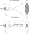
1 illustriert den Gesamtaufbau einer Anzeigeeinrichtung vom Projektionstyp gemäß den Prinzipien der vorliegenden Erfindung. 1 illustrates the overall construction of a projection type display device in accordance with the principles of the present invention.
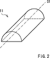
2 ist eine perspektivische Ansicht einer zylindrischen Linse, wie sie in 1 dargestellt ist. 2 is a perspective view of a cylindrical lens, as shown in FIG 1 is shown.
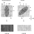
3A zeigt die Gestalt oder Form von Licht, welches von einer Lichtquelle in einer oder auf einer XY-Ebene ausgesendet wird. 3A shows the shape or form of light emitted by a light source in or on an XY plane.
3B illustriert eine Anordnung einer zylindrischen Linse in der XY-Ebene. 3B illustrates an arrangement of a cylindrical lens in the XY plane.
3C illustriert eine Anordnung mit einer Fliegenaugenlinse oder Facettenlinse in der XY-Ebene. 3C illustrates an arrangement with a fly-eye lens or facet lens in the XY plane.
4 zeigt einen Gesamtaufbau eines Vergleichs für eine Anzeigeeinrichtung vom Projektionstyp. 4 Fig. 10 shows an overall construction of a comparison for a projection type display device.
5A zeigt einen Zusammenhang zwischen axialen Richtungen oder Achsenrichtungen von Licht, welches in eine Facettenlinse oder Fliegenaugenlinse eintritt, und Anordnungsrichtungen von Linsen in der Facettenlinse oder Fliegenaugenlinse, und illustriert ein Interferenzmuster, welches auf einer beleuchteten oder bestrahlten Fläche oder Oberfläche erzeugt wird, und zwar gemäß der Anzeigeeinrichtung vom Projektionstyp zum Vergleich. 5A FIG. 16 shows a relationship between axial directions or axial directions of light entering a facet lens or fly-eye lens, and arrangement directions of lenses in the facet lens or fly-eye lens, and illustrates an interference pattern generated on an illuminated or irradiated area or surface according to FIG Display device of projection type for comparison.
5B zeigt einen Zusammenhang in der Anordnung zwischen axialen Richtungen von Licht, welches in die Facettenlinse oder Fliegenaugenlinse eintritt oder dort auftrifft, und Anordnungsrichtungen (arrangement directions) von Linsen in der Fliegenaugenlinse oder Facettenlinse und illustriert einen Zustand eines Interferenzmusters, welches auf einer beleuchteten oder bestrahlten Fläche oder Oberfläche erzeugt wird, und zwar gemäß den Prinzipien der vorliegenden Erfindung. 5B shows a relationship in the arrangement between axial directions of light entering or impinging the facet lens or fly-eye lens and arrangement directions of lenses in the fly-eye lens or facet lens and illustrating a state of an interference pattern which is on an illuminated or irradiated surface or surface is generated according to the principles of the present invention.
6A illustriert eine Anordnung von Licht, welches von einer Lichtquelle in der XY-Ebene ausgesandt wird, und zwar gemäß einer ersten Abwandlung der Anordnung aus 1. 6A illustrates an arrangement of light emitted from a light source in the XY plane, according to a first modification of the arrangement 1 ,
6B zeigt einen Zustand der Anordnung einer Facettenlinse oder Fliegenaugenlinse in der XY-Ebene gemäß der ersten Abwandlung. 6B Fig. 12 shows a state of arranging a facet lens or fly eye lens in the XY plane according to the first modification.
7A illustriert eine Anordnung von Licht, welches von einer Lichtquelle in der XY-Ebene ausgesandt wird, und zwar gemäß einer zweiten Abwandlung der Anordnung aus 1. 7A illustrates an arrangement of light emitted from a light source in the XY plane, according to a second modification of the arrangement 1 ,
7B zeigt einen Zustand der Anordnung einer Facettenlinse oder Fliegenaugenlinse in der XY-Ebene gemäß der zweiten Abwandlung. 7B Fig. 12 shows a state of arranging a facet lens or fly eye lens in the XY plane according to the second modification.
8 zeigt eine Gesamtanordnung einer Anzeigeeinrichtung vom Projektionstyp gemäß einer dritten Abwandlung der Anordnung aus 1. 8th Fig. 12 shows an overall arrangement of a projection type display device according to a third modification of the arrangement 1 ,
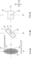
9A zeigt eine Ebenengestalt oder Ebenenform (plane shape) von Licht, welches von einer Lichtquelle in einer XY-Ebene ausgesandt ist oder wurde. 9A shows a plane shape or plane shape of light emitted from a light source in an XY plane.
9B zeigt eine Anordnung der zylindrischen Linse in der XY-Ebene. 9B shows an arrangement of the cylindrical lens in the XY plane.
9C zeigt eine Anordnung eines Stablichtintegrators in der XY-Ebene. 9C shows an arrangement of a bar light integrator in the XY plane.
10A, B sind perspektivische Ansichten des Stablichtintegrators aus 8. 10A , B are perspective views of the bar light integrator 8th ,
11A, B sind schematische Zeichnungen zum Beschreiben eines Prinzips des in 8 dargestellten Stablichtintegrators. 11A , B are schematic drawings for describing a principle of in 8th illustrated bar light integrator.
12A zeigt Licht, welches von einer Lichtquelle in der XY-Ebene ausgesandt ist oder wird und zwar gemäß einer dritten Abwandlung der Anordnung aus 1. 12A FIG. 12 shows light emitted from a light source in the XY plane, or according to a third modification of the arrangement. FIG 1 ,
12B zeigt einen Zustand der Anordnung des Stablichtintegrators in der XY-Ebene gemäß der dritten Abwandlung. 12B FIG. 12 shows a state of the arrangement of the bar light integrator in the XY plane according to the third modification.
13A zeigt einen Zustand der Anordnung von Licht, welches von einer Lichtquelle in der XY-Ebene ausgesandt ist oder wird, gemäß einer vierten Abwandlung der Anordnung aus 1. 13A FIG. 12 shows a state of the arrangement of light emitted from a light source in the XY plane according to a fourth modification of the arrangement 1 ,
13B zeigt einen Zustand der Anordnung des Stablichtintegrators in der XY-Ebene gemäß der vierten Abwandlung der Anordnung aus 1. 13B FIG. 12 shows a state of the arrangement of the bar light integrator in the XY plane according to the fourth modification of the arrangement 1 ,
14 zeigt einen Gesamtaufbau einer Anzeigeeinrichtung vom Projektionstyp gemäß einer fünften Abwandlung der Anordnung aus 1. 14 FIG. 12 shows an overall structure of a projection type display device according to a fifth modification of the arrangement 1 ,
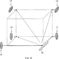
15 ist eine schematische Zeichnung zum Beschreiben weiterer Grundlagen und Prinzipien der vorliegenden Erfindung. 15 Fig. 12 is a schematic drawing for describing further principles and principles of the present invention.
DETAILBESCHREIBUNG BEVORZUGTER AUSFÜHRUNGSBEISPIELEDETAILED DESCRIPTION OF PREFERRED EMBODIMENTS
Nachfolgend werden einige Ausführungsbeispiele der vorliegenden Erfindung im Detail unter Bezugnahme auf die beigefügten Zeichnungen erläutert. Die Beschreibung in der dargestellten Reihenfolge:
- 1. Anfangausführungsform (Eine zylindrische Linse ist zwischen einer Laserlichtquelle und einer Facettenlinse geneigt angeordnet).
- 2. Erste Abwandlung und zweite Abwandlung (Die Laserlichtquelle oder die Facettenlinse sind geneigt angeordnet).
- 3. Dritte Abwandlung (Die zylindrische Linse ist zwischen der Laserlichtquelle und einem Stablichtintegrator geneigt angeordnet).
- 4. Vierte Abwandlung und fünfte Abwandlung (Die Laserlichtquelle oder der Stablichtintegrator sind geneigt angeordnet).
- 5. Sechste Abwandlung (Reflektive Flüssigkristalltafeln werden verwendet).
Hereinafter, some embodiments of the present invention will be explained in detail with reference to the accompanying drawings. The description in the order shown: - 1. Initial Embodiment (A cylindrical lens is disposed inclined between a laser light source and a facet lens).
- 2. First Modification and Second Modification (The laser light source or the facet lens are inclined).
- 3. Third Modification (The cylindrical lens is disposed between the laser light source and a bar light integrator).
- 4. Fourth Modification and Fifth Modification (The laser light source or the bar light integrator are inclined).
- 5. Sixth Modification (Reflective liquid crystal panels are used).
ERSTE/ANFANGSAUSFÜHRUNGSFORMFIRST / TOP EMBODIMENT
AUFBAU DER ANZEIGEEINRICHTUNG VOM PROJEKTIONSTYPCONSTRUCTION OF DISPLAY DEVICE FROM PROJECTION TYPE
1 zeigt in schematischer Art und Weise eine Konfiguration oder einen Aufbau einer Anzeigeeinrichtung 1 vom Projektionstyp (eine Bildanzeigeeinrichtung vom Projektionstyp; projection-type image display device) gemäß einer Ausführungsform der vorliegenden Erfindung. Die Anzeigeeinrichtung 1 vom Projektionstyp weist eine Laserlichtquelle 10, eine zylindrische Linse oder Zylinderlinse 11, eine Fliegenaugenlinse oder Facettenlinse 12 und eine Kondensorlinse 13 auf, die eine Beleuchtungseinrichtung 1a bilden. Die Anzeigeeinrichtung 1 vom Projektionstyp ist auch mit Spiegeln 14A bis 14E, transmissiven oder transmittierenden Flüssigkristalltafeln oder -elementen 15R, 15G und 15B, einem dichroischen oder dichroitischen Prisma 16 und einer Projektionslinse 17 ausgebildet, welche ein optisches Projektionssystem zum Projizieren eines Bildes auf einem Schirm 18 unter Verwendung von Licht aus der Beleuchtungseinrichtung 1a projizieren. 1 Fig. 12 shows a schematic configuration of a display device 1 of the projection type (a projection-type image display device) according to an embodiment of the present invention. The display device 1 The projection type has a laser light source 10 , a cylindrical lens or cylindrical lens 11 , a fly eye lens or faceted lens 12 and a condenser lens 13 on which is a lighting device 1a form. The display device 1 of the projection type is also with mirrors 14A to 14E , transmissive or transmissive liquid crystal panels or elements 15R . 15G and 15B , a dichroic or dichroic prism 16 and a projection lens 17 comprising an optical projection system for projecting an image on a screen 18 using light from the illumination device 1a project.
Die Laserlichtquelle 10 kann z. B. ein rotes Laserelement, ein grünes Laserelement und ein blaues Laserelement aufweisen (die Arten der Farben und die Anzahl der Farben ist nicht auf diese Ausführungsform beschränkt). Jedes der Laserelemente kann ein Halbleiterlaserelement, ein Festkörperlaserelement oder ein anderes geeignetes Element sein. Bevorzugt, aber nicht notwendigerweise wird ein Arraylaser vorgesehen, bei welchem eine Mehrzahl von Laserelementen verwendet wird, die uniaxial angeordnet sind. Das daraus ausgesandte Laserlicht kann ein Fernfeldmuster oder eine Fernfeldanordnung (FFP; far-field pattern) aufweisen, deren Gestalt z. B. eine elliptische ist. Das bedeutet, dass Licht (oder ein Lichtfluss), welcher angeregt (ausgegeben) wird oder von der Laserlichtquelle 10 ausgesandt wird (nachfolgend wird der Einfachheit halber einfach auf Laserlichtausgabelicht Bezug genommen), besitzt eine Kohärenzanisotropie in der Ebene (in-plane anisotropy in coherency), d. h. eine Anisotropie in der Kohärenz in einer Querschnittsebene des Lichtflusses.The laser light source 10 can z. As a red laser element, a green laser element and a blue laser element have (the types of colors and the number of colors is not limited to this embodiment). Each of the laser elements may be a semiconductor laser element, a solid state laser element or another suitable element. Preferably, but not necessarily, an array laser is provided using a plurality of laser elements that are uniaxially disposed. The laser light emitted therefrom may have a far-field pattern or a far-field pattern (FFP) whose shape is e.g. B. is an elliptical. This means that light (or a light flux) that is excited (emitted) or from the laser light source 10 is emitted (hereinafter simply referred to laser light emitting light for simplicity), has in-plane anisotropy in coherency, that is, anisotropy in coherence in a cross-sectional plane of the light flux.
Bei dieser Ausführungsform ist die Gestalt oder Form des Lichtquellenausgabelichts L0 eine Ellipse mit einer kleinen Halbachse in einer X-Richtung und einer großen Halbachse in einer Y-Richtung in einer XY-Ebene, wie dies in 3A dargestellt ist. Dies bedeutet mit anderen Worten, dass die Laserlichtquelle 10 so an einer oder in einer optischen Achse Z0 angeordnet ist, dass eine axiale Richtung oder Achsenrichtung DH, in welcher eine höchste Kohärenz des Lichts auftritt, überlappt oder übereinstimmt mit der X-Richtung, und dass eine axiale Richtung oder Achsenrichtung DL, in welcher eine niedrigste Kohärenz des Lichts auftritt, überlappt oder übereinstimmt mit der Y-Richtung im Lichtquellenausgabelicht L0. Eine derartige Aussage in Bezug auf die Anordnung oder die Ausgestaltung der Laserlichtquelle 10 wird nachfolgend als ”Referenzanordnung” der Laserlichtquelle 10 bezeichnet. Der Begriff ”Ebenengestalt” (plane shape) des Laserlichts bezieht sich nachfolgend auf eine Gestalt oder Form in der XY-Ebene.In this embodiment, the shape or shape of the light source output light L0 is an ellipse having a small half-axis in an X-direction and a large half-axis in a Y-direction in an XY plane as shown in FIG 3A is shown. In other words, that means the laser light source 10 is disposed on or on an optical axis Z0 such that an axial direction or axis direction D H in which highest coherence of the light occurs overlaps or coincides with the X direction, and that an axial direction or axis direction D L , in which has a lowest coherence of the light overlaps or coincides with the Y direction in the light source output light L0. Such a statement with respect to the arrangement or the design of the laser light source 10 is hereinafter referred to as "reference arrangement" of the laser light source 10 designated. The term "plane shape" of the laser light subsequently refers to a shape or shape in the XY plane.
Unter Bezugnahme auf 2 ist dargestellt, dass die zylindrische Linse oder Zylinderlinse eine halbzylindrische Linse sein kann, die sich uniaxial in einer axialen Richtung oder Achsenrichtung D1 erstreckt, d. h., die sich in einer Richtung in einer Querschnittsebene des Lichtflusses erstreckt. Bei dieser Ausführungsform ist die zylindrische Linse 11 so schräg oder geneigt in geneigter Art und Weise angeordnet, dass die axiale Richtung oder Achsenrichtung D1 der zylindrischen Linse 11 und die axiale Richtung oder Achsenrichtung DH, in welcher die höchste Kohärenz des Lichts auftritt, sich voneinander unterscheiden. Dies bedeutet insbesondere, dass, wie das in 3B dargestellt ist, die zylindrische Linse 11 so angeordnet ist, dass die axiale Richtung oder Achsenrichtung D1 davon von der X-Richtung um die optische Achse Z0 um einen vorbestimmten Winkel α rotiert ist. Der Winkel α wird in geeigneter Art und Weise eingestellt, so dass er einen Wert annimmt, welcher größer ist als 0° und geringer als 180° (außer 90° und 270°). Eine derartige Anordnung der Zylinderlinse 11 wird nachfolgend als ”geneigte Anordnung” (inclined arrangement) der Zylinderlinse 11 bezeichnet.With reference to 2 For example, it is illustrated that the cylindrical lens or cylindrical lens may be a semi-cylindrical lens that uniaxially extends in an axial direction or axis direction D1, ie, that extends in a direction in a cross-sectional plane of the light flux. In this embodiment, the cylindrical lens is 11 arranged obliquely or inclined in an inclined manner such that the axial direction or axis direction D1 of the cylindrical lens 11 and the axial direction or axis direction D H in which the highest coherence of the light occurs differ from each other. This means in particular that, as the in 3B is shown, the cylindrical lens 11 is arranged so that the axial direction or axis direction D1 thereof is rotated from the X-direction about the optical axis Z0 by a predetermined angle α. The angle α is suitably set to assume a value greater than 0 ° and less than 180 ° (except 90 ° and 270 °). Such an arrangement of the cylindrical lens 11 is hereinafter referred to as "inclined arrangement" (inclined arrangement) of the cylindrical lens 11 designated.
Die Fliegenaugenlinse oder Facettenlinse 12 besitzt einen Aufbau, bei welchem eine Mehrzahl von Linsen in zweidimensionaler Art und Weise z. B. auf einem Substrat angeordnet ist. Die Facettenlinse 12 unterteilt einen einfallenden Lichtfluss gemäß der Anordnung und Ausrichtung der Linsen in räumlicher Art und Weise und ermöglicht, dass ein unterteilter Lichtfluss oder unterteilte Lichtflüsse davon ausgegeben werden. Wie im Zusammenhang mit 3C dargestellt ist, kann die Facettenlinse 12 einen Aufbau aufweisen, bei welchem eine Mehrzahl von Linsen 12a in zwei Richtungen (in einer Matrix) angeordnet ist oder wird, wobei die Richtungen orthogonal zueinander ausgebildet sind (d. h. z. B. gemäß Anordnungsrichtungen C1 und C2). Bei dieser Ausführungsform ist die Facettenlinse 12 so an oder in der optischen Achse Z0 angeordnet, dass die Anordnungsrichtung C1 der Linsen 12A mit der Y-Richtung überlappt oder übereinstimmt und dass die Anordnungsrichtung C2 der Linsen 12a mit der X-Richtung überlappt oder übereinstimmt. Eine derartige Anordnung der Facettenlinse 12 wird nachfolgend als ”Referenzanordnung” (reference arrangement) der Facettenlinse 12 bezeichnet. The fly eye lens or facetted lens 12 has a structure in which a plurality of lenses in a two-dimensional manner z. B. is arranged on a substrate. The facetted lens 12 spatially divides an incident light flux in accordance with the arrangement and orientation of the lenses, and allows a subdivided light flux or subdivided light fluxes to be output therefrom. As related to 3C is shown, the facet lens 12 have a structure in which a plurality of lenses 12a is arranged in two directions (in a matrix), the directions being orthogonal to each other (ie, according to arrangement directions C1 and C2, for example). In this embodiment, the facet lens is 12 arranged on or in the optical axis Z0 such that the arrangement direction C1 of the lenses 12A overlaps or coincides with the Y direction and that the arrangement direction C2 of the lenses 12a overlaps or coincides with the X direction. Such an arrangement of the facet lens 12 is hereinafter referred to as the "reference arrangement" of the facet lens 12 designated.
Die Kondensorlinse 13 dient dem Multiplexen des in der Facettenlinse 12 unterteilten Lichts. Das Multiplexen mittels der Kondensorlinse 13 wird entlang der Anordnungs- oder Orientierungsrichtungen der Linsen 12a in der Facettenlinse 12 durchgeführt. Das bedeutet bei dieser Ausführungsform, dass Richtungen des Multiplexens mittels der Kondensorlinse 13 in der X-Richtung und in der Y-Richtung liegen.The condenser lens 13 serves to multiplex the in the facet lens 12 divided light. The multiplexing by means of the condenser lens 13 becomes along the arrangement or orientation directions of the lenses 12a in the facet lens 12 carried out. That means in this embodiment that directions of multiplexing by means of the condenser lens 13 in the X direction and in the Y direction.
Die Kondensorlinse 13 und die Facettenlinse 12 korrespondieren mit einem illustrativen Beispiel eines optischen Elements. Die Facettenlinse 12 und die Kondensorlinse 13 sind in Kombination miteinander so angeordnet, um den einfallenden Lichtfluss, der aus dem Lichtquellenausgabelicht L0 abgeleitet ist, zu unterteilen und die unterteilten Lichtfluxe, die aus dem Lichtquellenausgabelicht L0 abgeleitet sind, zu multiplexen, um dadurch eine gleichförmige Luminanz, Leuchtdichte, Leuchtstärke, Lichtmenge, Helligkeit oder Luminanz in der Ebene zu erreichen.The condenser lens 13 and the facet lens 12 correspond to an illustrative example of an optical element. The facetted lens 12 and the condenser lens 13 are arranged in combination with each other so as to subdivide the incident light flux derived from the light source output light L0 and to multiplex the divided light fluxes derived from the light source output light L0 to thereby obtain uniform luminance, luminance, luminous intensity, amount of light, To achieve brightness or luminance in the plane.
Die Spiegel 14A bis 14E separieren oder trennen das Licht (Beleuchtungslicht), welches von der Beleuchtungseinrichtung 1a ausgegeben wird, in Farblichtanteile roten Lichts (R), grünen Lichts (G) und blauen Lichts (B) und bewirken eine Änderung des optischen Pfads in Bezug auf die getrennten Farblichtkomponenten oder Farblichtarten, um jede der separierten Farblichtkomponenten oder Farblichtarten auf eine Flüssigkristalltafel einer entsprechenden Farbe (d. h. auf eine transmittive oder transmittierende Flüssigkristalltafel 15R, 15G oder 15B) hinzurichten. Dies bedeutet insbesondere, dass jeder der Spiegel 14A und 14E die Änderung des optischen Pfads (optical-path conversion) durchführt mittels Reflexion in Bezug auf das rote Licht, um dieses der transmittiven oder transmittierenden Flüssigkristalltafel 15R zuzuführen. In ähnlicher Art und Weise führt oder richtet der Spiegel 14B das blaue Licht zu der transmittiven oder transmittierenden Flüssigkristalltafel 15B. Jeder der Spiegel 14C und 14D richtet oder führt das grüne Licht zur transmittiven oder transmittierenden Flüssigkristalltafel 15G. Unter diesen Spiegeln 14A bis 14E transmittiert der Spiegel 14A in selektiver Art und Weise das grüne Licht und das blaue Licht. Der Spiegel 14B transmittiert selektiv das grüne Licht.The mirror 14A to 14E separate or separate the light (illumination light) emitted by the illumination device 1a in color light components of red light (R), green light (G) and blue light (B), and cause a change in the optical path with respect to the separated color light components or color light types to each of the separated color light components or color light types on a liquid crystal panel of a corresponding one Color (ie on a transmittive or transmitting liquid crystal panel 15R . 15G or 15B to execute). This means in particular that each of the mirrors 14A and 14E the optical-path conversion is carried out by reflection with respect to the red light, that of the transmissive or transmissive liquid crystal panel 15R supply. Similarly, the mirror guides or directs 14B the blue light to the transmissive or transmissive liquid crystal panel 15B , Each of the mirrors 14C and 14D the green light directs or guides to the transmissive or transmissive liquid crystal panel 15G , Under these mirrors 14A to 14E the mirror transmits 14A in a selective way, the green light and the blue light. The mirror 14B selectively transmits the green light.
Die transmittiven oder transmittierenden Flüssigkristalltafeln 15R, 15G und 15B modulieren das rote Licht, das grüne Licht und das blaue Licht auf der Grundlage eines Bildsignals und erzeugen Anzeigebildlichtkomponenten für die Farben Rot, Grün bzw. Blau. Jeder der transmittiven oder transmittierenden Flüssigkristalltafeln 15R, 15G und 15B kann einen nicht dargestellten Aufbau besitzen, bei welchem eine Flüssigkristallschicht zwischen einem Paar von Substraten, die sich gegenüberstehen, eingeschlossen und versiegelt ist. Dabei kann ein Polarisator jeweils auf der Lichteinfallsseite und der Lichtausgangsseite des Paares von Substraten vorgesehen sein. Wenn eine zu einem Bildsignal korrespondierende vorbestimmte Spannung an jede der Flüssigkristallschichten der transmittierenden oder transmittiven Flüssigkristalltafeln 15R, 15G und 15B angelegt ist oder wird, werden die Farblichtkomponenten (color lights), die durch die Flüssigkristallschichten passieren, moduliert, so dass entsprechende jeweilige Bildlichtkomponenten (image lights) ausgegeben werden.The transmissive or transmissive liquid crystal panels 15R . 15G and 15B modulate the red light, the green light, and the blue light based on an image signal, and produce red, green, and blue display image light components, respectively. Each of the transmissive or transmissive liquid crystal panels 15R . 15G and 15B may have a structure, not shown, in which a liquid crystal layer between a pair of substrates, which are facing each other, enclosed and sealed. In this case, a polarizer may be respectively provided on the light incident side and the light output side of the pair of substrates. When a predetermined voltage corresponding to an image signal is applied to each of the liquid crystal layers of the transmissive or transmissive liquid crystal panels 15R . 15G and 15B is applied, the color light components (color lights) passing through the liquid crystal layers are modulated to output corresponding respective image light components (image lights).
Das dichroische oder dichroitische Prisma 16 kann ein Farbsynthetisierungsprisma (color-synthesizing prism) sein, welches ein so genanntes Cross-Dichroic-Prisma oder ein geeignetes anderes optisches Element sein kann. Das dichroitische Prisma 16 dient dazu, die Bildlichtkomponenten der Farben Rot, Grün und Blau, die zuvor beschrieben wurden, zu synthetisieren und insbesondere miteinander in Kombination zusammenzusetzen. Die Projektionslinse 17 dient dazu, das durch das dichroitische Prisma 16 synthetisierte oder zusammengeführte Bildlicht in vergrößerter Art und Weise zu projizieren.The dichroic or dichroic prism 16 may be a color-synthesizing prism, which may be a so-called cross-dichroic prism or a suitable other optical element. The dichroic prism 16 serves to synthesize the image light components of the colors red, green and blue described above, and in particular to combine them together in combination. The projection lens 17 This is done through the dichroic prism 16 synthesized or merged image light in an enlarged manner.
BETRIEB UND WIRKUNG DER ANZEIGEEINRICHTUNG VOM PROJEKTIONSTYPOPERATION AND EFFECT OF DISPLAY DEVICE FROM PROJECTION TYPE
Der Betrieb und die Wirkung der Anzeigeeinrichtung vom Projektionstyp 1 wird nun unter Bezugnahme auf die 1 bis 5B beschrieben.The operation and effect of the projection type display device 1 will now be with reference to the 1 to 5B described.
Bei der Anzeigeeinrichtung 1 vom Projektionstyp passiert das Licht das von der Laserlichtquelle 10 ausgesendet wird (also das Lichtquellenausgabelicht L0) zunächst durch die zylindrische Linse 11 und tritt dann in die Facettenlinse 12 in der Beleuchtungseinrichtung 1a ein. Wenn das Lichtquellenausgabelicht L0 auf die Facettenlinse 12 auftrifft oder einfällt, wird ein Einfallslicht (nachfolgend als Einfallslicht L1 (incident light) bezeichnet) davon in zueinander angeordnete Richtungen gemäß den Linsen 12a unterteilt. Dann wird das in der Facettenlinse 12 unterteilte Licht in der Kondensorlinse 13 gemultiplext. Das gemultiplexte Licht tritt aus der Kondensorlinse 13 aus. Die Lichtdichte des Ausgabelichts in der Ebene (in-plane luminance) (also des Beleuchtungslichts) aus der Beleuchtungseinrichtung 1a ist oder wird dadurch gleichmäßig oder gleichförmig ausgebildet. Dann wird das Beleuchtungslicht in die drei Farblichtkomponenten (color lights) für rotes Licht, grünes Licht und blaues Licht aufgetrennt oder separiert, welche dann entsprechend geführt werden, um dann auf die jeweiligen transmittierenden Flüssigkristalltafeln 15R, 15G bzw. 15B zu treffen. In den transmittierenden Flüssigkristalltafeln 15R, 15G und 15B werden die Farblichtkomponenten dann entsprechend moduliert. Die modulierten Farblichtkomponenten treten dann als jeweilige Bildlichtkomponenten aus. Die Bildlichtekomponenten der jeweiligen Farben werden dann im dichroitischen Prisma 16 synthetisiert oder zusammengesetzt. Das synthetisierte oder zusammengesetzte Licht wird dann auf den Schirm 18 in vergrößerter Art und Weise mittels der Projektionslinse 17 projiziert. Dadurch wird das Abbilden eines Bildes erreicht.In the display device 1 The light from the laser light source passes from the projection type 10 is emitted (that is, the light source output light L0) first through the cylindrical lens 11 and then enters the facet lens 12 in the lighting device 1a one. When the light source output L0 is on the facet lens 12 incident or incident, an incident light (hereinafter referred to as incident light L1 (incident light)) thereof is arranged in mutually arranged directions according to the lenses 12a divided. Then that will be in the facet lens 12 divided light in the condenser lens 13 multiplexed. The multiplexed light emerges from the condenser lens 13 out. The light density of the output light in the plane (in-plane luminance) (ie the illumination light) from the illumination device 1a is or is formed by uniform or uniform. Then, the illumination light is separated or separated into the three red light, green light, and blue light color lights, which are then guided, respectively, and then onto the respective transmitting liquid crystal panels 15R . 15G respectively. 15B hold true. In the transmitting liquid crystal panels 15R . 15G and 15B The color light components are then modulated accordingly. The modulated color light components then emerge as respective image light components. The image light components of the respective colors are then in the dichroic prism 16 synthesized or assembled. The synthesized or compound light is then placed on the screen 18 in an enlarged manner by means of the projection lens 17 projected. This achieves the mapping of an image.
Nachfolgend wird eine Anzeigeeinrichtung vom Projektionstyp gemäß einem Vergleichsbeispiel unter Bezugnahme auf die 4 und 5A erläutert. Die 4 zeigt einen Gesamtüberblick oder den Gesamtaufbau der Anzeigeeinrichtung 100 vom Projektionstyp gemäß dem Vergleichsbeispiel. 5A zeigt einen Zusammenhang im Hinblick auf die Anordnung zwischen einem Lichtquellenausgabelicht L100 und einer Facettelinse 102 in der Anzeigeeinrichtung 100 vom Projektionstyp und zeigt auch einen Zustand im Hinblick auf ein Interferenzmuster, welches auf einer belichteten oder beleuchteten Fläche oder Oberfläche erzeugt wird. Die Anzeigeeinrichtung 100 vom Projektionstyp ist mit einer Laserlichtquelle 101, einer Facettenlinse 102, einer Kondensorlinse 103, Spiegeln 104A bis 104E, transmittierenden Flüssigkristalltafeln 105R, 105G und 105B einem dichroitischen Prisma 106 und einer Projektionslinse 107 ausgebildet, welche entlang einer optischen Achse Z0 vorgesehen sind.Hereinafter, a projection type display device according to a comparative example will be described with reference to FIGS 4 and 5A explained. The 4 shows an overall view or the overall structure of the display device 100 of the projection type according to the comparative example. 5A shows a relationship with regard to the arrangement between a light source output light L100 and a facile lens 102 in the display device 100 of the projection type and also shows a condition with respect to an interference pattern generated on an exposed or illuminated surface or surface. The display device 100 The projection type is with a laser light source 101 , a faceted lens 102 , a condenser lens 103 , Flipping 104A to 104E , transmitting liquid crystal panels 105R . 105G and 105B a dichroic prism 106 and a projection lens 107 formed, which are provided along an optical axis Z0.
Die Anzeigeeinrichtung 100 vom Projektionstyp mit dem zuvor beschriebenen Aufbau weist die Laserlichtquelle 101 und die Facettenlinse 102 in einer Anordnung auf, die bei dieser Ausführungsform ”Referenzanordnung” genannt wird. Dies bedeutet, wie dies im oberen Bereich der 5A dargestellt ist, dass die Laserlichtquelle 101 so angeordnet ist, dass die axiale Richtung oder Achsenrichtung DH, in welcher die höchste Kohärenz des Lichts auftritt, im Lichtquellenausgabelicht L100 überlappt oder zusammenfällt mit der X-Richtung und dass die axiale Richtung oder Achsenrichtung DL, in welcher die niedrigste Kohärenz des Lichts erscheint, im Lichtquellenausgabelicht L100 überlappt oder zusammenfällt mit der Y-Richtung. Dies bedeutet andererseits, dass die Facettenlinse 102 so angeordnet ist, dass die Anordnungs- oder Ausrichtungsrichtungen der Linsen 102 überlappen oder zusammenfallen mit der X-Richtung und der Y-Richtung. Wenn jedoch sowohl die Laserlichtquelle 100 und die Facettenlinse 102 so angeordnet sind, dass sie die Referenzanordnungen einnehmen oder besitzen, überlappen oder fallen die Richtung DH im Lichtquellenausgabelicht L100 und die Anordnungsrichtungen der Linsen 102A (d. h. die Richtungen des Multiplexens, welches durch die Kondensorlinse 103 durchgeführt wird) miteinander in der X-Richtung. Wenn ein derartiges Überlappen oder Zusammenfallen der Achsenrichtung bewirkt oder erzeugt wird, wird das Multiplexen entlang der Richtung DH im Lichtquellenausgabelicht L100, in welcher die höchste Kohärenz des Lichts erscheint, durchgeführt. Folglich ist es im Hinblick auf das Beleuchtungslicht nach dem Austritt aus der Kondensorlinse 103 wahrscheinlicher, dass ein Interferenzmuster auf der beleuchteten oder bestrahlten Fläche auftritt, wie dies im unteren Bereich der 5A dargestellt ist.The display device 100 The projection type with the above-described construction has the laser light source 101 and the facet lens 102 in an arrangement called "reference arrangement" in this embodiment. This means like this at the top of the 5A is shown that the laser light source 101 is arranged so that the axial direction or axis direction D H in which the highest coherence of light occurs in the light source output light L100 overlaps or coincides with the X direction and that the axial direction or axis direction D L , in which the lowest coherence of the light appears in the light source output L100 overlaps or coincides with the Y direction. On the other hand, this means that the facet lens 102 is arranged so that the arrangement or alignment directions of the lenses 102 overlap or coincide with the X direction and the Y direction. However, if both the laser light source 100 and the facet lens 102 are arranged so as to occupy or have the reference arrangements, the direction D H in the light source output light L100 and the arrangement directions of the lenses overlap or fall 102A (ie, the directions of multiplexing that pass through the condenser lens 103 performed) with each other in the X direction. When such an overlap or collapse of the axis direction is caused or generated, the multiplexing along the direction D H in the light source output light L100 in which the highest coherence of the light appears is performed. Consequently, it is with respect to the illumination light after the exit from the condenser lens 103 more likely that an interference pattern occurs on the illuminated or irradiated surface, as in the lower region of the 5A is shown.
Im Gegensatz dazu ist bei der erfindungsgemäßen Ausführungsform die Zylinderlinse 11 so angeordnet, dass sie die geneigte Anordnung zwischen der Laserlichtquelle 10 und der Facettenlinse 12 annimmt. Dies bedeutet, dass die Zylinderlinse 11 so angeordnet ist, dass die axiale Richtung D1 davon um die optische Z0 um den Winkel α rotiert ist. Wenn das Lichtquellenausgabelicht L0 (nämlich Licht, das entlang des optischen Pfads A läuft), die Zylinderlinse 11 passiert, wird dadurch die Ebenenform oder Ebenengestalt des Lichtquellenausgabelichts L100 gemäß dem Winkel α rotiert und tritt dann aus der Zylinderlinse 11 aus. Dies bedeutet, dass die Achsenrichtung DH im Licht L1, welches die Facettenlinse 12 nach dem Austreten aus der Zylinderlinse 11 eintritt (nämlich Licht, das entlang dem optischen Pfad B verläuft), sich unterscheidet von den Linsenanordnungsrichtungen C1 und C2 (welche äquivalent sind zur X-Richtung und Y-Richtung), wie dies im Zusammenhang mit dem oberen Bereich der 5B dargestellt ist. Dies bewirkt, dass die axiale Richtung DH des einfallenden Lichts L1, welches in die Facettenlinse 12 tritt, und die Richtungen des Multiplexens mittels der Kondensorlinse 13 voneinander unterschiedlich sind, wodurch verhindert wird, dass das Multiplexen entlang der Achsenrichtung DH auftritt, in welcher die Kohärenz am höchsten ist. Folglich tritt in Bezug auf das Beleuchtungslicht nach dem Austritt aus der Kondensorlinse 13 mit geringerer Wahrscheinlichkeit ein Interferenzmuster auf. Zumindest jedoch ist das Interferenzmuster, sollte es auftreffen, weniger stark lichtsichtbar auf der bestrahlten oder beleuchteten Fläche oder Oberfläche, wie dies in Zusammenhang mit dem unteren Bereich der 5B dargestellt ist.In contrast, in the embodiment of the invention, the cylindrical lens 11 arranged so that they are the inclined arrangement between the laser light source 10 and the facet lens 12 accepts. This means that the cylinder lens 11 is arranged so that the axial direction D1 thereof is rotated about the optical Z0 by the angle α. When the light source output light L0 (namely, light that travels along the optical path A), the cylinder lens 11 As a result, the plane shape or plane shape of the light source output light L100 is thereby rotated according to the angle α and then exits the cylindrical lens 11 out. This means that the axis direction D H in the light L1, which is the facet lens 12 after exiting the cylinder lens 11 occurs (namely, light that passes along the optical path B) differs from the lens arrangement directions C1 and C2 (which are equivalent to the X direction and Y direction), as related to the upper portion of the 5B is shown. This causes the axial direction D H of the incident light L 1, which is in the facet lens 12 occurs, and the directions of multiplexing by means of the condenser lens 13 are different from each other, thereby preventing the multiplexing from occurring along the axis direction D H in which the coherence is highest. Consequently, with respect to the illumination light, after exiting the condenser lens, it will occur 13 less likely to have an interference pattern. At least, however, the interference pattern, should it strike, less visible to light on the irradiated or illuminated area or surface, as related to the lower area of the 5B is shown.
Wie vorangehend beschrieben wurde, verweist bei dieser Ausführungsform die Beleuchtungseinrichtung die Laserlichtquelle 10, die Zylinderlinse 11, die Facettenlinse 12 und eine Kondensorlinse 13 auf, die in dieser Reihenfolge entlang der optischen Achse Z0 vorgesehen und angeordnet sind. Des Weiteren ist bei der Beleuchtungseinrichtung sowohl die Laserlichtquelle 10 als auch die Facettenlinse 12 so angeordnet, dass sie die Bezugsanordnung einnehmen, wogegen die Zylinderlinse 11 so angeordnet ist, dass sie die geneigte Anordnung (sie ist rotiert in der XY-Ebene) annimmt. Dadurch wird es möglich, dass die axiale Richtung oder Achsenrichtung DH des einfallenden Lichts L1, welches auf die Facettenlinse 12 trifft, und die Richtungen de Multiplexens mittels der Kondensorlinse 13 sich voneinander unterscheiden. Dadurch wird verhindert, dass Lichtstrahlen entlang der Achsenrichtung DH, in welcher die Kohärenz am höchsten ist, gemultiplext werden. Daher ist es möglich, dass etwaig entstehende Interferenzmuster auf der bestrahlten oder beleuchteten Oberfläche weniger sichtbar sind.As described above, in this embodiment, the illumination device refers the laser light source 10 , the cylindrical lens 11 , the faceted lens 12 and a condenser lens 13 which are provided and arranged in this order along the optical axis Z0. Furthermore, in the illumination device, both the laser light source 10 as well as the facet lens 12 arranged so that they occupy the reference arrangement, whereas the cylindrical lens 11 is arranged so that it assumes the inclined arrangement (it is rotated in the XY plane). Thereby, it becomes possible that the axial direction or axis direction D H of the incident light L 1 incident on the facet lens 12 meets, and the directions of multiplexing by means of the condenser lens 13 differ from each other. This prevents light beams from being multiplexed along the axis direction D H in which the coherence is highest. Therefore, it is possible that any resulting interference patterns are less visible on the irradiated or illuminated surface.
Bei derzeitig erhältlichen Techniken, z. B. bei Mechanismen zum rotierbaren Antreiben eines Ablenkspiegels zwischen der Laserlichtquelle und der Facettenlinse, werden ein optisches Element mit einer speziellen Ausgestaltung zum Ändern eines apparenten optischen Pfads in Bezug auf jeden unterteilten Lichtfluss oder dergleichen vorgesehen zum Zwecke des Unterdrückens des Erzeugens von Interferenzmustern wegen des Unterteilens und des Multiplexens von Lichtflüssen. Daher sind derzeit erhältliche Techniken vergleichsweise kostenintensiv und komplex im Hinblick auf ihren Aufbau. Entsprechend der beschriebenen Ausführungsform sind jedoch derartige Mechanismen zum rotierbaren Antreiben, spezielle optische Elemente oder dergleichen nicht mehr notwendig. Stattdessen ist die vorliegende Ausführungsform dahingehend vorteilhaft, als dass sie die zylindrische Linse in einer geneigten Art und Weise oder Anordnung im optischen Pfad vorsieht. Daher ist es möglich, dass etwaig auftretende Interferenzmuster mittels dieser Anordnung auf einfache und weniger kostenintensive Art und Weise eine geringere Sichtbarkeit besitzen als herkömmlicherweise.With currently available techniques, e.g. In mechanisms for rotatably driving a deflection mirror between the laser light source and the facet lens, an optical element having a specific configuration for changing an apparent optical path with respect to each divided light flux or the like is provided for the purpose of suppressing the generation of interference patterns due to the division and the multiplexing of light fluxes. Therefore, currently available techniques are relatively expensive and complex in terms of their design. However, according to the described embodiment, such mechanisms for rotatable driving, special optical elements or the like are no longer necessary. Instead, the present embodiment is advantageous in that it provides the cylindrical lens in an inclined manner or arrangement in the optical path. Therefore, it is possible that any occurring interference pattern by means of this arrangement in a simple and less expensive way, have a lower visibility than conventional.
ABWANDLUNGEN UND MODIFIKATIONENCONVERSIONS AND MODIFICATIONS
Nachfolgend werden erste bis sechste Abwandlungen der Ausführungsform, die oben beschrieben wurde, erläutert. Zu bemerken ist dabei, dass dieselben oder äquivalente oder gleich wirkende Elemente, wie diejenigen, die in Zusammenhang mit der Anzeigeeinrichtung 1 vom Projektionstyp gemäß der oben beschriebenen Ausführungsform beschrieben wurden, mit denselben Bezugszeichen bezeichnet werden. Eine Detailbeschreibung erfolgt in diesem Fall nicht erneut.Hereinafter, first to sixth modifications of the embodiment described above will be explained. It should be noted that the same or equivalent or equivalent elements, such as those associated with the display device 1 of the projection type according to the above-described embodiment, will be denoted by the same reference numerals. A detailed description will not be made in this case.
ERSTE ABWANDLUNGFIRST CONVERSION
Die 6A zeigt einen Zustand der Anordnung des Lichtquellenausgabelichts L0 in der XY-Ebene. 6B zeigt einen Zustand der Anordnung der Facettenlinse 12 in der XY-Ebene gemäß der ersten Abwandlung. Wie bei der oben beschriebenen Ausführungsform bewirkt auch die erste Abwandlung ein Unterteilen und ein Multiplexen von Lichtflüssen mittels der Facettenlinse 12 und des Kondensors 13, und zwar auf der Grundlage des Ausgabelichts aus der Laserlichtquelle 10 in der Belichtungseinrichtung. Auch ist das Ausgabelicht aus der Kondensorlinse 13 als Beleuchtungslicht oder Belichtungslicht für ein optisches Projektionssystem nutzbar, welches einen Aufbau aufweist, der zu dem Aufbau der oben beschriebenen Ausführungsform ähnlich ist (das bedeutet, die Spiegel 14A bis 14E, transmittierende Flüssigkristalltafeln 15R, 15G und 15B, ein dichroitisches Prisma 16 und eine Projektionslinse 17 vorgesehen sind).The 6A Fig. 15 shows a state of the arrangement of the light source output light L0 in the XY plane. 6B shows a state of the arrangement of the facet lens 12 in the XY plane according to the first modification. As in the embodiment described above, the first modification also causes division and multiplexing of light fluxes by means of the facet lens 12 and the condenser 13 on the basis of the output light from the laser light source 10 in the exposure device. Also, the output light is from the condenser lens 13 as illumination light or exposure light for an optical projection system having a structure similar to the structure of the above-described embodiment (that is, the mirrors 14A to 14E , transmitting liquid crystal panels 15R . 15G and 15B , a dichroic prism 16 and a projection lens 17 are provided).
Die erste Abwandlung unterscheidet sich von dem oben beschriebenen Ausführungsbeispiel darin, dass die zylindrische Linse 11 nicht vorgesehen ist und dass das Lichtquellenausgabelicht L0 direkt auf die Facettenlinse 12 trifft. Wie ebenso in 6A dargestellt ist, ist die Laserlichtquelle 10 so schräg oder geneigt von einem Zustand der Referenzanordnung aus ausgerichtet oder angeordnet, dass die axiale Richtung oder Achsenrichtung DH in welcher die höchste Kohärenz des Lichts erscheint, im Lichtquellenausgabelicht L0 unterschiedlich ist von der X-Richtung und der Y-Richtung. Das bedeutet, dass die Laserlichtquelle 10 um die optische Achse Z0 um einen vorbestimmten Winkel rotiert ist. Ein derartiger Zustand in Bezug auf die Laserlichtquelle 10 wird nachfolgend als ”geneigte Anordnung” der Laserlichtquelle 10 bezeichnet. Auf der anderen Seite ist, wie dies in 6B dargestellt ist, die Facettenlinse 12 in der Referenzanordnung vorgesehen.The first modification differs from the embodiment described above in that the cylindrical lens 11 is not provided and that the light source output L0 directly to the facet lens 12 meets. Likewise in 6A is shown is the laser light source 10 oriented or arranged obliquely or inclined from a state of the reference arrangement such that the axial direction or axis direction D H in which the highest coherence of the light appears in the light source output light L0 is different from the X direction and the Y direction. That means the laser light source 10 is rotated about the optical axis Z0 by a predetermined angle. Such a condition with respect to the laser light source 10 is hereinafter referred to as "inclined arrangement" of the laser light source 10 designated. On the other hand, like this is in 6B is shown, the facet lens 12 provided in the reference arrangement.
Auf diese Art und Weise kann die Laserlichtquelle 10 selbst eine geneigte Anordnung besitzen, ohne dass die zylindrische Linse 11 benötigt und verwendet wird. Dies bedeutet, dass die axiale Richtung DH im Lichtquellenausgabelicht L0 sich von den Linsenanordnungsrichtungen C1 und C2 (welche äquivalent sind zur X-Richtung und zur Y-Richtung) in der Facettenlinse 12 voneinander verschieden sind. Dies bewirkt, dass die axiale Richtung DH des in die Facettenlinse 12 eintretenden Lichts und die Richtungen des Multiplexens mittels der Kondensorlinse 13 (in den 6A und 6B nicht dargestellt; siehe jedoch 1) voneinander unterschiedlich sind, so dass es möglich wird, zu verhindern, dass Lichtstrahlen entlang der axialen Richtung DH gemultiplext werden, in welcher die Kohärenz am stärksten ist. Daher ist es nötig, eine Wirkung zu erzielen, die äquivalent ist zu derjenigen des oben beschriebenen Ausführungsbeispiels. Da die Zylinderlinse 11 bei der ersten Abwandlung nicht vorgesehen und verwendet wird, ist es auch möglich, einen einfacheren Aufbau mit einer verminderten Anzahl von Komponenten zu erreichen.In this way, the laser light source 10 even have a tilted arrangement without the cylindrical lens 11 needed and used. That is, the axial direction D H in the light source output light L0 is different from the lens arrangement directions C1 and C2 (which are equivalent to the X direction and the Y direction) in the facet lens 12 are different from each other. This causes the axial direction D H of the facet lens 12 incoming light and the directions of multiplexing by means of the condenser lens 13 (in the 6A and 6B not shown; see, however 1 ) are different from each other, so that it becomes possible to prevent light beams from being multiplexed along the axial direction D H in which the coherence is strongest. Therefore, it is necessary to obtain an effect equivalent to that of the embodiment described above. Because the cylindrical lens 11 is not provided and used in the first modification, it is also possible to achieve a simpler structure with a reduced number of components.
ZWEITE ABWANDLUNGSECOND CONVERSION
7A zeigt einen Zustand der Anordnung des Lichtquellenausgabelichts L0 in der XY-Ebene. 7B zeigt einen Zustand der Anordnung der Facettenlinse 12 in der XY-Ebene gemäß der zweiten Abwandlung. Wie bei der oben beschriebenen Ausführungsform führt die zweite Abwandlung das Unterteilen und das Multiplexen der Lichtflüsse mittels der Facettenlinse 12 mittels der Kondensorlinse 13 auf der Grundlage des aus der Laserlichtquelle 10 austretenden Ausgabelichts in der Beleuchtungseinrichtung aus. Auch hier ist das Ausgabelicht der Kondensorlinse 13 als Belichtungslicht oder Beleuchtungslicht für ein optisches Projektionssystem verwendbar, welches eine Anordnung ähnlich zu derjenigen der oben beschriebenen Ausführungsform besitzt (d. h. Spiegel 14A bis 14E, transmittierende Flüssigkristalltafeln 15R, 15G und 15B, das dichroitische Prisma 16 und die Projektionslinse 17 sind vorgesehen). Des Weiteren besitzt die zweite Abwandlung eine Anordnung, bei welcher die zylindrische Linse 11 nicht angeordnet ist und bei welcher das Lichtquellenausgabelicht L0 direkt auf die Facettenlinse trifft, nämlich in der gleichen Art und Weise wie bei der oben beschriebenen ersten Abwandlung. 7A Fig. 15 shows a state of the arrangement of the light source output light L0 in the XY plane. 7B shows a state of the arrangement of the facet lens 12 in the XY plane according to the second modification. As in the embodiment described above, the second modification performs the dividing and the multiplexing of the light fluxes by means of the facet lens 12 by means of the condenser lens 13 on the basis of the laser light source 10 exiting output light in the lighting device off. Again, the output light is the condenser lens 13 usable as exposure light or illumination light for a projection optical system having an arrangement similar to that of the above-described embodiment (ie, mirror 14A to 14E , transmitting liquid crystal panels 15R . 15G and 15B , the dichroic prism 16 and the projection lens 17 are provided). Furthermore, the second modification has an arrangement in which the cylindrical lens 11 is not arranged and in which the light source output light L0 is incident directly on the facet lens, in the same manner as in the first modification described above.
Die zweite Abwandlung unterscheidet sich von der oben beschriebenen ersten Abwandlung dahingehend, dass die Laserlichtquelle 10 die oben beschriebene Referenzanordnung besitzt, wie dies im Zusammenhang mit 7A gezeigt ist. Wie in 7B dargestellt ist, unterscheidet sich die zweite Abwandlung von der oben beschriebenen Ausführungsform und von der ersten Abwandlung dahingehend, dass die Facettenlinse 12 so geneigt oder schräg in Bezug auf den Zustand der Bezugsanordnung ausgerichtet ist, dass die Linsenanordnungsrichtungen C1 und C2 sich voneinander von der X-Richtung und der Y-Richtung unterscheiden. Eine derartige Anordnung in Bezug auf die Facettenlinsen 12 wird nachfolgend als ”geneigte Anordnung” für die Facettenlinse 12 bezeichnet.The second modification is different from the first modification described above in that the laser light source 10 has the reference arrangement described above, as in connection with 7A is shown. As in 7B 2, the second modification differs from the above-described embodiment and the first modification in that the facet lens 12 is oriented obliquely or obliquely with respect to the state of the reference arrangement such that the lens arrangement directions C1 and C2 are different from each other from the X direction and the Y direction. Such an arrangement with respect to the facet lenses 12 is hereinafter referred to as "inclined arrangement" for the facet lens 12 designated.
Auf diese Art und Weise kann die Facettenlinse 12 selbst eine geneigte oder schräge Anordnung annehmen, ohne dass eine zylindrische Linse oder die zylindrische Linse 11 verwendet werden muss. Folglich unterscheidet sich die axiale Richtung DH in dem Lichtquellenausgabelicht L100 von den Linsenanordnungsrichtungen C1 und C2 in der Facettenlinse 12. Dies bewirkt, dass die axiale Richtung DH in dem auf die Facettenlinse 12 auftretenden Licht und die Richtungen des Multiplexens mittels der Kondensorlinse 13 (in den 7A und 7B nicht dargestellt; siehe jedoch 1) sich voneinander unterscheiden, wodurch es möglich wird, zu verhindern, dass Lichtstrahlen entlang der axialen Richtung DH, in welcher die Kohärenz am höchsten ist, gemultiplext werden. Daher ist es möglich, eine äquivalente Wirkung oder einen gleichen Effekt zu erzielen, wie bei der Ausführungsform und der ersten Abwandlung, die oben beschrieben wurden.In this way, the facet lens can 12 assume even a tilted or oblique arrangement without a cylindrical lens or the cylindrical lens 11 must be used. Consequently, the axial direction D H in the light source output light L100 differs from the lens array directions C 1 and C 2 in the facet lens 12 , This causes the axial direction D H in the on the facet lens 12 occurring light and the directions of multiplexing by means of the condenser lens 13 (in the 7A and 7B not shown; see, however 1 ) are different from each other, thereby making it possible to prevent light beams from being multiplexed along the axial direction D H in which the coherence is highest. Therefore, it is possible to obtain an equivalent effect or effect as in the embodiment and the first modification described above.
Bei den ersten und zweiten Abwandlungen, die oben beschrieben wurden, wurde entweder die Laserlichtquelle 10 oder die Facettenlinse 12 so angeordnet, dass sie eine geneigte Anordnung besaßen. Bei einer Ausführungsform können sowohl die Laserlichtquelle 10 als auch die Facettenlinse 12 so angeordnet werden, dass sie zueinander unterschiedlich geneigte Anordnungen besitzen. Dies bedeutet, dass die Laserlichtquelle 10 und die Facettenlinse 12 so angeordnet sind oder werden, dass die Laserlichtquelle 10 und die Facettenlinse 12 relativ um die optische Achse Z0 gedreht sind oder werden, dass das Lichtquellenausgabelicht L0 und die Linsenanordnungsrichtungen C1 und C2 in der Facettenlinse 12 relativ zueinander unterschiedlich sind. Folglich können die Laserlichtquelle 10 und die Facettenlinse 12 so angeordnet werden, dass die Richtung, in welcher die höchste Kohärenz des Lichts im emittierten Lichtfluss aus der Laserlichtquelle 10 erscheint, unterschiedlich ist von den Richtungen des Multiplexens.In the first and second modifications described above, either the laser light source became 10 or the facet lens 12 arranged so that they had a tilted arrangement. In one embodiment, both the laser light source 10 as well as the facet lens 12 be arranged so that they have mutually different inclined arrangements. This means that the laser light source 10 and the facet lens 12 are arranged or are that the laser light source 10 and the facet lens 12 are relatively rotated about the optical axis Z0 or that the light source output light L0 and the lens arrangement directions C1 and C2 in the facet lens 12 are different relative to each other. Consequently, the laser light source can 10 and the facet lens 12 be arranged so that the direction in which the highest coherence of the light in the emitted light flux from the laser light source 10 appears different from the directions of multiplexing.
DRITTE ABWANDLUNGTHIRD IMPROVEMENT
8 zeigt einen Gesamtaufbau einer Anzeigeeinrichtung 2 vom Projektionstyp (Bildanzeigeeinrichtung vom Projektionstyp), und zwar gemäß einer dritten Abwandlung. Wie bei der Anzeigeeinrichtung 1 vom Projektionstyp gemäß der beschriebenen Ausführungsform, so bestrahlt auch die Anzeigeeinrichtung 2 vom Projektionstyp mittels Beleuchtungslicht, welches aus der Laserlichtquelle 10 austritt, aus einer Beleuchtungseinrichtung 2a ein entsprechendes optisches Projektionssystem (mit Spiegeln 14A bis 14E, transmittierenden Flüssigkristalltafeln 15R, 15G und 15B, einem dichroitischen Prisma 16 und einer Projektionslinse 17). Auch ist die Laserlichtquelle 10 so angeordnet, dass sie die Referenzanordnung gemäß 9A einnimmt. Die zylindrische Linse 11 ist so angeordnet, dass sie geneigte Anordnung gemäß 9B einnimmt. 8th shows an overall structure of a display device 2 of the projection type (image display device of the projection type), according to a third modification. As with the display device 1 of the projection type according to the described embodiment, so the display device irradiated 2 of the projection type by means of illumination light, which from the laser light source 10 exit, from a lighting device 2a a corresponding optical projection system (with mirrors 14A to 14E , transmitting liquid crystal panels 15R . 15G and 15B , a dichroic prism 16 and a projection lens 17 ). Also, the laser light source 10 arranged so that they comply with the reference arrangement 9A occupies. The cylindrical lens 11 is arranged so that it inclines according to 9B occupies.
Die dritte Abwandlung unterscheidet sich von der oben beschriebenen Ausführungsform dahingehend, dass der Stablichtintegrator 20 (nachfolgend als Stabintegrator bezeichnet) als optisches Element verwendet wird zum Unterteilen und Multiplexen der Lichtflüsse. Dies bedeutet insbesondere, dass der Stabintegrator 20 zwischen der zylindrischen Linse 11 und dem Spiegel 14A angeordnet ist, und zwar anstelle der Facettenlinse 12 und der Kondensorlinse 13, die bei der oben beschriebenen Ausführungsform vorgesehen sind. Dabei ist die Kondensorlinse 13 auf einer Lichteinfallsseite des Stabintegrators 20 angeordnet.The third modification differs from the embodiment described above in that the bar light integrator 20 (hereinafter referred to as a rod integrator) is used as an optical element for dividing and multiplexing the light fluxes. This means in particular that the rod integrator 20 between the cylindrical lens 11 and the mirror 14A is arranged, instead of the facet lens 12 and the condenser lens 13 which are provided in the embodiment described above. Here is the condenser lens 13 on a light incident side of the bar integrator 20 arranged.
Die 10A und 10B illustrieren jeweils ein Beispiel für einen Stabintegrator 20. Der Stabintegrator 20 kann ein rechteckiges, prismenartiges Glasgebildet nach Art eines Glasstabs 20A sein, wie dies im Zusammenhang mit 10A dargestellt ist. Der Glasstab 20A besitzt eine Lichteinfallsfläche 20A1 und eine Lichtausgangsfläche 20A2, welche einander gegenüberliegen. Die Ebenengestalt oder Ebenenform der Lichteinfallsfläche 20A1 und diejenige der Lichtausgangsfläche 20A2 können z. B. rechteckig oder rechtwinklig sein. Eine gemäß 10A dargelegte Anordnung ermöglicht, dass der von der Lichteinfallsseite 20A1 eintretende Lichtfluss virtuell unterteilt wird durch eine mehrfache interne Totalreflexion, und zwar korrespondierend mit einem Winkel des Auseinanderlaufens oder einem Divergenzwinkel des Einfallslichts und einer Länge des Stabintegrators 20 (eine Länge entlang der Z-Achsenrichtung). Dadurch wird ein Unterteilen der nachfolgenden zu multiplexenden Lichtflüsse auf die Lichtausgangsseite oder -fläche 20A2 hin ermöglicht. Folglich ist die Lichtdichte in der Ebene im Ausgabelicht gleichförmig oder gleichmäßig ausgebildet.The 10A and 10B each illustrate an example of a rod integrator 20 , The rod integrator 20 may be a rectangular, prism-like glass formed in the manner of a glass rod 20A be like this related to 10A is shown. The glass rod 20A has a light incident surface 20A1 and a light output surface 20A2 which are opposite each other. The plane shape or plane shape of the light incident surface 20A1 and that of the light output surface 20A2 can z. B. rectangular or rectangular. One according to 10A set forth arrangement allows that of the light incident side 20A1 the incoming light flux is virtually subdivided by a multiple total internal reflection, corresponding to an angle of divergence or a divergence angle of the incident light and a length of the rod integrator 20 (a length along the Z-axis direction). This divides the subsequent light fluxes to be multiplexed onto the light output side or surface 20A2 towards. Consequently, the light density in the plane in the output light is uniform or uniform.
Alternativ dazu kann, wie das im Zusammenhang mit 2B dargestellt ist, der Stabintegrator 20 auch ein rechteckiger und prismenartiger Hohlkörper 20B sein, dessen innere Flächen z. B. Spiegelflächen sind. Der Hohlkörper 20B besitzt eine Lichteinfallsfläche oder Einfallsseite 20B1 (eine Lichteinfallsöffnung) und eine Lichtausgangsseite oder -fläche 20B2 (eine Lichtausgangsöffnung), die einander gegenüberstehen oder gegenüberliegen. Die Ebenen- oder Flächengestalt oder -form (die Öffnungsgestalt oder Öffnungsform) der Lichteinfallsfläche 20B1 und diejenige (Öffnungsgestalt/Öffnungsform) der Lichtausgangsfläche 20B2 können z. B. rechtwinklig oder rechteckig sein. Eine derartige Anordnung gemäß 10B ermöglicht es, dass der Lichtfluss, der aus der Lichteingangsfläche 20B1 eintritt, virtuell unterteilt wird, mittels mehrfacher interner Totalreflexionen, und zwar korrespondierend zu einem Divergenzwinkel oder Winkel des Auseinanderlaufendes Einfallslichts oder einfallenden Lichts und der Länge des Stabintegrators 20. Dadurch wird ermöglicht, dass die unterteilten Lichtflüsse nachfolgend auf die Lichtausgangsseite oder Lichtausgangsfläche 20B2 hin gemultiplext werden. Dadurch wird die Lichtdichte oder Beleuchtungsdichte in der Ebene in Bezug auf das Ausgabelicht oder Ausgangslicht gleichförmig oder gleichmäßig gestaltet.Alternatively, as related to 2 B is shown, the rod integrator 20 also a rectangular and prismatic hollow body 20B be whose inner surfaces z. B. mirror surfaces. The hollow body 20B has a light incident surface or incident side 20B1 (a light incident opening) and a light output side or surface 20B2 (a light exit opening) facing or facing each other. The plane or surface shape or shape (the opening shape or opening shape) of the light incident surface 20B1 and that (opening shape / opening shape) of the light output surface 20B2 can z. B. be rectangular or rectangular. Such an arrangement according to 10B allows the flow of light coming from the light input surface 20B1 is virtually divided by multiple internal total reflections, corresponding to a divergence angle or angle of divergence of the incident light or incident light and the length of the rod integrator 20 , This allows the subdivided light fluxes to follow the light output side or the light output surface 20B2 be multiplexed. Thereby, the light density or the illumination density in the plane with respect to the output light or output light is made uniform or uniform.
Nachfolgend wird ein Grundprinzip des Stabintegrators 20 gemäß dieser Abwandlung unter Bezugnahme auf die 11A und 11B beschrieben. Falls der Stabintegrator 20 nicht verwendet wird, wird das auf die Kondensorlinse 13 einfallende Laserlicht (L2) durch die Kondensorlinse 13 gesammelt. Das gesammelte Licht verteilt sich dann oder wird gestreut (Laserlicht L100, wie dies in 11A dargestellt ist). Wenn andererseits der Stabintegrator 20 verwendet wird, wird das Laserlicht L2 durch die Kondensorlinse 13 gesammelt, das gesammelte Licht tritt dann in den Stabintegrator 20 ein. Das eingetretene Licht wiederholt im Inneren des Stabintegrators 20 eine mehrfache Totalreflexion, durch welche das Licht virtuell in eine Mehrzahl von Lichtstrahlen unterteilt wird. Folglich werden die Lichtstrahlen (Laserlicht L3 in 11B) in der Lichtausgangsfläche oder auf der Lichtausgangsseite des Stabintegrators 20 gemultiplext, und zwar gemäß der Größe und der Gestalt der Lichtaustrittsfläche (oder der Öffnung).The following is a basic principle of the rod integrator 20 according to this modification with reference to the 11A and 11B described. If the rod integrator 20 is not used, that is on the condenser lens 13 incident laser light (L2) through the condenser lens 13 collected. The collected light is then distributed or scattered (laser light L100, as shown in 11A is shown). On the other hand, if the rod integrator 20 is used, the laser light L2 through the condenser lens 13 collected, the collected light then enters the rod integrator 20 one. The occurred light repeats inside the rod integrator 20 a multiple total reflection, by which the light is virtually divided into a plurality of light beams. As a result, the light beams (laser light L3 in FIG 11B ) in the light output surface or on the light output side of the rod integrator 20 multiplexed according to the size and shape of the light exit surface (or opening).
Unter Bezugnahme auf 9C ist gezeigt, dass der Stabintegrator 20 so angeordnet werden kann, dass eine lange Seite und eine kurze Seite, in der Ebenengestalt parallel zur Lichteinfallsfläche und Lichtaustrittsfläche davon, entlang der X-Richtung und der Y-Richtung verlaufen. Das Multiplexen mittels des Stabintegrators 20 wird in den Richtungen entlang der reflektierenden Flächen oder Oberflächen (Wandflächen) ausgeführt. Das bedeutet bei dieser Abwandlung, dass die Richtungen des Multiplexens des Stabintegrators 20 in der X-Richtung und der Y-Richtung liegen. Eine derartige Anordnung in Bezug auf den Stabintegrator 20 wird nachfolgend ”Referenzanordnung” des Stabintegrators 20 bezeichnet.With reference to 9C is shown that the rod integrator 20 can be arranged so that a long side and a short side, in the plane shape parallel to the light incident surface and light exit surface thereof, extend along the X direction and the Y direction. Multiplexing by means of the rod integrator 20 is performed in the directions along the reflective surfaces or surfaces (wall surfaces). This means in this modification that the directions of multiplexing of the rod integrator 20 lie in the X direction and the Y direction. Such an arrangement with respect to the rod integrator 20 is hereinafter referred to as "reference arrangement" of the rod integrator 20 designated.
Gemäß der dritten Abwandlung ist die zylindrische Linse 11 so angeordnet, dass sie zwischen der Laserlichtquelle 10 und dem Stabintegrator 20 die geneigte Anordnung annimmt. Dadurch ist das Lichtquellenausgabelicht L0 (Licht, das entlang des optischen Pfads A in 8 läuft) in der zylindrischen Linse 11 rotiert und tritt aus der zylindrischen Linse 11 aus. Folglich sind die axiale Richtung DH im Licht, welches in den Stabintegrator 20 eintritt, nachdem es aus der zylindrischen Linse 11 ausgetreten ist (Licht, welches entlang dem optischen Pfad B in 8 verläuft) und die Richtungen des Multiplexens im Stabintegrator 20 voneinander verschieden, wodurch es möglich wird, zu verhindern, dass Lichtstrahlen entlang der axialen Richtung DH gemultiplext werden, in welcher die Kohärenz am höchsten ist. Daher ist es möglich, einen ähnlichen Effekt und eine ähnliche Wirkung zu erzielen, wie bei der oben beschriebenen Ausführungsform.According to the third modification, the cylindrical lens is 11 arranged so that they are between the laser light source 10 and the rod integrator 20 the inclined arrangement assumes. As a result, the light source output light L0 (light incident along the optical path A in FIG 8th running) in the cylindrical lens 11 rotates and exits the cylindrical lens 11 out. Consequently, the axial direction D H in the light, which in the rod integrator 20 enters after leaving the cylindrical lens 11 leaked (light, which along the optical path B in 8th runs) and the directions of multiplexing in the rod integrator 20 different from each other, thereby making it possible to prevent light beams from being multiplexed along the axial direction D H in which the coherence is highest. Therefore, it is possible to obtain a similar effect and effect as in the embodiment described above.
VIERTE ABWANDLUNG FOURTH DIFFERENCE
Die 12A zeigt einen Zustand der Anordnung des Lichtquellenausgabelichts L0 in der XY-Ebene. 12B zeigt einen Zustand der Anordnung des Stabintegrators 20 in der XY-Ebene gemäß der vierten Abwandlung. Wie bei der dritten Abwandlung, die oben beschrieben wurde, so führt auch die vierte Abwandlung ein Unterteilen und ein Multiplexen des Ausgabelichts aus der Laserlichtquelle 10 in der Beleuchtungseinrichtung im Stabintegrator 20 aus. Es ist ebenso das Ausgabelicht des Stabintegrators 20 als Beleuchtungslicht für das optische Projektionssystem verwendbar, welches einen Aufbau besitzt, der ähnlich ist zu demjenigen bei der Ausführungsform, die oben beschrieben wurde (d. h., Spiegel 14A bis 14E, transmittierende Flüssigkristalltafeln 15R, 15G und 15B, ein dichroitisches Prisma 16 und eine Projektionslinse 17 sind vorgesehen).The 12A Fig. 15 shows a state of the arrangement of the light source output light L0 in the XY plane. 12B shows a state of the arrangement of the rod integrator 20 in the XY plane according to the fourth modification. As in the third modification described above, the fourth modification also performs division and multiplexing of the output light from the laser light source 10 in the illumination device in the rod integrator 20 out. It is also the output of the rod integrator 20 as the illumination light for the projection optical system having a structure similar to that in the embodiment described above (ie, mirrors 14A to 14E , transmitting liquid crystal panels 15R . 15G and 15B , a dichroic prism 16 and a projection lens 17 are provided).
Die vierte Abwandlung unterscheidet sich von der Ausführungsform und von der dritten Abwandlung, die oben beschrieben wurde, dahingehend, dass die zylindrische Linse 11 nicht vorgesehen ist und dass das Lichtquellenausgabelicht L0 direkt in den Stabintegrator 20 eintritt. Darüber hinaus ist, wie das in 12A dargestellt ist, die Laserlichtquelle 10 so angeordnet, dass sie in einer geneigten Anordnung vorliegt, wogegen der Stabintegrator 20 so angeordnet ist, dass er die Referenzanordnung einnimmt, wie das in 12B gezeigt ist.The fourth modification differs from the embodiment and the third modification described above in that the cylindrical lens 11 is not provided and that the Lichtquellenausgabelicht L0 directly into the rod integrator 20 entry. In addition, like that in 12A is shown, the laser light source 10 arranged so that it is in an inclined arrangement, whereas the rod integrator 20 is arranged so that it occupies the reference arrangement, as in 12B is shown.
Auf diese Art und Weise kann die Laserlichtquelle 10 selbst die geneigte Anordnung einnehmen, ohne dass eine zylindrische Linse 11 verwendet wird. Folglich werden die axiale Richtung DH im Lichtquellenausgabelicht L0 und die Richtungen des Multiplexens des Stabintegrators 20 voneinander verschieden, wodurch es möglich wird, zu verhindern, dass die Lichtstrahlen entlang der Achsenrichtung DH gemultiplext werden, in welcher die Kohärenz am höchsten ist. Daher ist es möglich, eine Wirkung und einen Effekt zu erzielen, die äquivalent sind zu denjenigen der oben beschriebenen dritten Abwandlung. Da darüber hinaus eine zylindrische Linse 11 bei dieser Abwandlung nicht verwendet wird, ist es möglich, einen vereinfachten Aufbau mit einer verringerten Anzahl von Bauteilen zu erhalten.In this way, the laser light source 10 even take the inclined arrangement without a cylindrical lens 11 is used. Consequently, the axial direction D H in the light source output light L0 and the directions of multiplexing of the rod integrator become 20 different from each other, thereby making it possible to prevent the light beams from being multiplexed along the axis direction D H in which the coherence is highest. Therefore, it is possible to obtain an effect and effect equivalent to those of the third modification described above. In addition, there is a cylindrical lens 11 is not used in this modification, it is possible to obtain a simplified structure with a reduced number of components.
FÜNFTE ABWANDLUNGFIFTH DIFFERENCE
Die 13A zeigt einen Zustand der Anordnung des Lichtquellenausgabelichts in der XY-Ebene. Die 13B zeigt einen Zustand der Anordnung des Stabintegrators 20 in der XY-Ebene. Beide Darstellungen erfolgen gemäß einer fünften Abwandlung. Wie bei der dritten Abwandlung, die oben beschrieben wurde, führt die fünfte Abwandlung ein Unterteilen und ein Multiplexen des Ausgabelichts der Laserlichtquelle 10 in der Beleuchtungseinrichtung im Stabintegrator 20 durch. Auch ist hier wieder das Ausgabelicht aus dem Stabintegrator 20 als Beleuchtungslicht für ein optisches Projektionssystem verwendbar, welches eine Anordnung besitzt, die zu derjenigen der oben beschriebenen Ausführungsform ähnlich ist (d. h., Spiegel 14A bis 14E, transmittierende Flüssigkristalltafeln 15R, 15G und 15B, ein dichroitisches Prisma 16 und eine Projektionslinse 17 sind vorgesehen). Des Weiteren besitzt die fünfte Abwandlung eine Anordnung, bei welcher die zylindrische Linse 11 nicht vorgesehen und angeordnet ist und das Lichtquellenausgabelicht L0 den Stab direkt in den Stabintegrator 20 eintritt, und zwar wie bei der vierten Abwandlung, die oben beschrieben wurde.The 13A Fig. 10 shows a state of the arrangement of the light source output light in the XY plane. The 13B shows a state of the arrangement of the rod integrator 20 in the XY plane. Both representations are made according to a fifth modification. As in the third modification described above, the fifth modification performs division and multiplexing of the output light of the laser light source 10 in the illumination device in the rod integrator 20 by. Again, here is the output light from the rod integrator 20 usable as an illumination light for a projection optical system having an arrangement similar to that of the above-described embodiment (ie, mirrors 14A to 14E , transmitting liquid crystal panels 15R . 15G and 15B , a dichroic prism 16 and a projection lens 17 are provided). Furthermore, the fifth modification has an arrangement in which the cylindrical lens 11 is not provided and arranged and the Lichtquellenausgabelicht L0 the rod directly into the rod integrator 20 occurs, as in the fourth modification described above.
Bei dieser Abwandlung besitzt die Laserlichtquelle 10 die Referenzanordnung, wie dies in 13A illustriert ist. Andererseits ist der Stabintegrator 20 derart geneigt angeordnet, und zwar in Bezug auf die Referenzanordnung, dass die Richtungen des Multiplexens sich von der X-Richtung und Y-Richtung unterscheiden, wie dies in 13B dargestellt ist. Das bedeutet, dass der Stabintegrator 20 um die optische Achse Z um einen vorbestimmten Winkel herum gedreht ist oder wird. Ein Zustand mit einer derartigen Anordnung für den Stabintegrator 20 wird nachfolgend als ”geneigte Anordnung” für den Stabintegrator 20 bezeichnet.In this modification, the laser light source has 10 the reference arrangement, as in 13A is illustrated. On the other hand, the rod integrator 20 arranged so inclined, with respect to the reference arrangement, that the directions of multiplexing differ from the X-direction and Y-direction, as shown in FIG 13B is shown. That means the rod integrator 20 is rotated about the optical axis Z by a predetermined angle or is. A condition with such an arrangement for the rod integrator 20 is hereinafter referred to as "inclined arrangement" for the rod integrator 20 designated.
Auf diese Art und Weise kann der Stabintegrator 20 selbst eine geneigte Anordnung besitzen, ohne die zylindrische Linse 11 zu verwenden. Folglich werden die axiale Richtung (DH) in dem Lichtquellenausgabelicht L0 und die Richtungen des Multiplexens im Stabintegrator 20 voneinander verschieden, wodurch es möglich wird, zu verhindern, dass die Lichtstrahlen entlang der axialen Richtung DH gemultiplext werden, in welcher die Kohärenz am höchsten ist. Es ist daher möglich, eine Wirkung und einen Effekt zu erzielen, die äquivalent sind zu denjenigen der oben beschriebenen dritten und vierten Abwandlungen.In this way, the rod integrator 20 even have a tilted arrangement, without the cylindrical lens 11 to use. Consequently, the axial direction (D H ) in the light source output light L0 and the directions of multiplexing in the rod integrator become 20 different from each other, thereby making it possible to prevent the light beams from being multiplexed along the axial direction D H in which the coherence is highest. It is therefore possible to obtain an effect and effect equivalent to those of the above-described third and fourth modifications.
Bei den vierten und fünften Abwandlungen, die oben beschrieben wurden, besaßen entweder die Laserlichtlichtquelle 10 oder der Stabintegrator 20 eine geneigte Anordnung. Bei einer Ausführungsform können sowohl die Laserlichtquelle 10 als auch der Stabintegrator zueinander unterschiedlich geneigte Anordnungen besitzen. Das bedeutet, dass die Laserlichtquelle 10 und der Stabintegrator 20 so angeordnet sein können, dass die Laserlichtquelle 10 und der Stabintegrator 20 relativ um die optische Achse Z0 herum rotiert sind oder werden, und zwar derart, dass das Lichtquellenausgabelicht L0 und die Richtungen des Multiplexens im Stabintegrator 20 relativ zueinander unterschiedlich sind. Folglich können die Laserlichtquelle 10 und der Stabintegrator 20 so angeordnet sein oder werden, dass die Richtung, in welcher die höchste Kohärenz des Lichts im emittierten Lichtfluss aus der Laserlichtquelle 10 vorliegt, unterschiedlich ist zu den Richtungen des Multiplexens.The fourth and fifth modifications described above had either the laser light source 10 or the rod integrator 20 a tilted arrangement. In one embodiment, both the laser light source 10 as well as the rod integrator have mutually different inclined arrangements. That means the laser light source 10 and the rod integrator 20 can be arranged so that the laser light source 10 and the rod integrator 20 are relatively rotated about the optical axis Z0 or so, in such a way that the light source output light L0 and the directions of multiplexing in the rod integrator 20 are different relative to each other. Consequently, the laser light source can 10 and the rod integrator 20 be arranged so that the direction in which the highest coherence of the light in the emitted Light flux from the laser light source 10 is different than the directions of multiplexing.
SECHSTE ABWANDLUNGSIXTH ADAPTATION
14 zeigt einen Gesamtaufbau einer Anzeigeeinrichtung 3 vom Projektionstyp (eine Bildanzeigeeinrichtung vom Projektionstyp) gemäß einer sechsten Abwandlung. Die Anzeigeeinrichtung 3 vom Projektionstyp weist eine Beleuchtungseinrichtung 1a auf, die ähnlich ist zu derjenigen der Anzeigeeinrichtung 1 vom Projektionstyp gemäß der oben beschriebenen Ausführungsform. Des Weiteren sind ebenso wie bei der oben beschriebenen Ausführungsform das dichroitische Prisma 16 und die Projektionslinse 17 in dem optischen Projektionssystem sowie ein Schirm 18 vorgesehen. Jedoch unterscheidet sich die sechste Abwandlung von der oben beschriebenen Ausführungsform dahingehend, dass die reflektiven Flüssigkristalltafeln 22R, 22G und 22B als die Flüssigkristalltafeln im optischen Projektionssystem verwendet werden. Des Weiteren sind auch Spiegel 21A bis 21F zum Trennen oder Separieren des Beleuchtungslichts, welches von der Beleuchtungseinrichtung 1a ausgegeben wird, in drei Farbkomponenten sowie zum Führen der Farbkomponenten auf die reflektiven Flüssigkristalltafeln 22R, 22G und 22B. 14 shows an overall structure of a display device 3 of the projection type (a projection type image display device) according to a sixth modification. The display device 3 The projection type has a lighting device 1a which is similar to that of the display device 1 of the projection type according to the embodiment described above. Further, as in the embodiment described above, the dichroic prism is 16 and the projection lens 17 in the optical projection system as well as a screen 18 intended. However, the sixth modification differs from the embodiment described above in that the reflective liquid crystal panels 22R . 22G and 22B as the liquid crystal panels are used in the projection optical system. Furthermore, there are mirrors 21A to 21F for separating or separating the illumination light emitted by the illumination device 1a in three color components and for guiding the color components to the reflective liquid crystal panels 22R . 22G and 22B ,
Jede der reflektiven Flüssigkristalltafeln 22R, 22G und 22B moduliert das Beleuchtungslicht aus der Beleuchtungseinrichtung 1a auf der Grundlage eines Bildsignals und reflektiert dasselbe, um zu ermöglichen, dass das so erzeugte Bildlicht auf derselben Seite austritt, wie derjenigen Seite, auf welcher das Licht zuvor eingetreten ist. Jede der reflektiven Flüssigkristalltafeln 22R, 22G und 22B weist eine reflektive Flüssigkristalleinrichtung auf, welche eine LCoS-Einrichtung (Liquid Crystal on Silicon) oder eine andere geeignete reflektive Flüssigkristalleinrichtung sein kann.Each of the reflective liquid crystal panels 22R . 22G and 22B modulates the illumination light from the illumination device 1a on the basis of an image signal and reflects the same to enable the image light thus generated to exit on the same side as the side on which the light has previously entered. Each of the reflective liquid crystal panels 22R . 22G and 22B has a reflective liquid crystal device which may be an LCoS device (Liquid Crystal on Silicon) or another suitable reflective liquid crystal device.
Die Spiegel 21A bis 21D trennen oder separieren das Beleuchtungslicht in rotes Licht, grünes Licht und blaues Licht (die Lichtarten und die Anzahl der Farben ist nicht auf diese Ausführungsform beschränkt) und führen jede der getrennten oder separierten Farblichtkomponenten der reflektiven Flüssigkristalltafeln 22R, 22G oder 22B einer entsprechenden Farbe zu. Unter diesen Spiegeln 21A bis 21D reflektiert der Spiegel 21A rotes Licht selektiv und transmittiert grünes Licht und blaues Licht. Der Spiegel 21B reflektiert selektiv grünes Licht und transmittiert blaues Licht selektiv. Jeder der Spiegel 21E bis 21G transmittiert selektiv Licht einer bestimmten Polarisation (z. B. einer S-Polarisation) und reflektiv selektiv Licht einer anderen Polarisation (z. B. einer P-Polarisation). Bei jeder der reflektiven Flüssigkristalltafeln 22R, 22G und 22B wird die Polarisation des Lichts zum Zeitpunkt des Einfalls darauf und die Polarisation des Lichts zum Zeitpunkt des Austritts davon voneinander unterschiedlich ausgebildet. Dies bedeutet insbesondere, dass die Farblichtkomponenten, die die Spiegel 21A bis 21D passiert haben, zunächst die Spiegel 21E bis 21G durchdringen. Dann treffen die Farblichtkomponenten die korrespondierenden reflektiven Flüssigkristalltafeln 22R, 22G bzw. 22B. Da die Farblichtkomponenten die reflektiven Flüssigkristalltafeln 22R, 22G und 22B als Bildlichtkomponenten oder als Bildlicht verlassen, ist die Polarisation der Lichtkomponenten unterschiedlich zu denjenigen zum Zeitpunkt des Lichteinfalls, diese Farblichtkomponenten werden von den Spiegeln 21E bis 21G reflektiert und die reflektierten Farblichtkomponenten treffen dann jeweils auf das dichroitische Prisma 16.The mirror 21A to 21D separate or separate the illuminating light into red light, green light and blue light (the types of light and the number of colors are not limited to this embodiment) and guide each of the separated or separated color light components of the reflective liquid crystal panels 22R . 22G or 22B to a corresponding color. Under these mirrors 21A to 21D the mirror reflects 21A red light selectively and transmits green light and blue light. The mirror 21B selectively reflects green light and selectively transmits blue light. Each of the mirrors 21E to 21G selectively transmits light of a particular polarization (eg, an S-polarization) and selectively selectively transmits light of a different polarization (eg, a P-polarization). For each of the reflective liquid crystal panels 22R . 22G and 22B For example, the polarization of the light at the time of incidence thereon and the polarization of the light at the time of exit therefrom are different from each other. This means in particular that the colored light components that the mirrors 21A to 21D have happened, first the mirrors 21E to 21G penetrate. Then, the color light components meet the corresponding reflective liquid crystal panels 22R . 22G respectively. 22B , Because the colored light components are the reflective liquid crystal panels 22R . 22G and 22B as image light components or as image light, the polarization of the light components is different from that at the time of incident light, these color light components are from the mirrors 21E to 21G reflected and the reflected color light components then each hit the dichroic prism 16 ,
Wie bei der oben beschriebenen Ausführungsform passiert bei der Anzeigeeinrichtung 3 vom Projektionstyp gemäß dieser Abwandlung das von der Laserlichtquelle 10 ausgesandte Licht zunächst durch die zylindrische Linse 11 und trifft dann auf die Facettenlinse 12, um darin in der Beleuchtungseinrichtung 1a aufgeteilt zu werden. Dann wird das in der Facettenlinse 12 aufgeteilte Licht in der Kondensorlinse 13 gemultiplext. Das gemultiplexte Licht verlässt die Kondensorlinse 13 als Beleuchtungslicht. Dann wird das Beleuchtungslicht durch die Spiegel 21A bis 21G in die drei Farblichtkomponenten für rotes Licht, grünes Licht und blaues Licht unterteilt, die dann zu den jeweiligen reflektiven Flüssigkristalltafeln 22R, 22G bzw. 22B geführt werden, und in diese eintreten. Dann werden die Farblichtkomponenten in den reflektiven Flüssigkristalltafeln 22R, 22G und 22B moduliert. Die modulierten Farblichtkomponenten treten dann als Bildlicht oder Bildlichtkomponenten jeweils aus. Dann werden die Bildlichtkomponenten der jeweiligen Farben im dichroitischen Prisma 16 synthetisiert oder zusammengeführt. Dann wird das zusammengeführte oder synthetisierte Licht auf den Schirm 18 mittels der Projektionslinse 17 in vergrößerter Art und Weise projiziert. Auf diese Art und Weise erfolgt das Abbilden eines Bildes. Dabei ist die zylindrische Linse 11 so angeordnet, dass sie die geneigte Anordnung oder Stellung einnimmt. Folglich wird das Multiplexen des in die Facettenlinse 12 eintretenden Lichts (Licht, welches entlang des optischen Pfads B in 14 läuft) in der Linsenanordnungsrichtung der Facettenlinse 12, d. h. ein Multiplexen entlang der axialen Richtung DH, in welcher die Kohärenz des Einfallslichts am höchsten ist, vermieden. Daher ist es möglich, eine Wirkung und einen Effekt zu erzielen, welcher zu denjenigen bei der oben beschriebenen Ausführungsform äquivalent ist.As in the above-described embodiment, the display device happens 3 of the projection type according to this modification, that of the laser light source 10 emitted light first through the cylindrical lens 11 and then hits the facet lens 12 in order to be in the lighting device 1a to be split. Then that will be in the facet lens 12 split light in the condenser lens 13 multiplexed. The multiplexed light leaves the condenser lens 13 as illumination light. Then the illumination light goes through the mirrors 21A to 21G divided into the three color light components for red light, green light and blue light, which then to the respective reflective liquid crystal panels 22R . 22G respectively. 22B be led and enter into this. Then, the color light components become in the reflective liquid crystal panels 22R . 22G and 22B modulated. The modulated color light components then emerge as image light or image light components, respectively. Then, the image light components of the respective colors in the dichroic prism 16 synthesized or combined. Then the merged or synthesized light is put on the screen 18 by means of the projection lens 17 projected in an enlarged manner. In this way, the picture is taken. Here is the cylindrical lens 11 arranged so that it assumes the inclined arrangement or position. Consequently, the multiplexing of the into the facet lens 12 incoming light (light, which along the optical path B in 14 is running) in the lens arranging direction of the facet lens 12 , that is, a multiplexing along the axial direction D H , in which the coherence of the incident light is highest, avoided. Therefore, it is possible to obtain an effect and an effect equivalent to those in the embodiment described above.
Obwohl die Erfindung beschrieben wurde im Zusammenhang mit einem Beispiel unter Bezugnahme auf eine Ausführungsform und deren Abwandlungen, ist die Erfindung nicht auf diese Ausgestaltungsformen und deren Abwandlungen beschränkt, sondern kann in vielfältiger Weise modifiziert werden. Bei der Ausführungsform und den Abwandlungen, die oben beschrieben wurde, war die zylindrische Linse 11 gegebenenfalls geneigt angeordnet zwischen der Laserlichtquelle 10 und einem Lichtunterteilungs-Multiplexelement, um zu ermöglichen, dass die axiale Richtung, in welcher die höchste Kohärenz des Lichts auftritt, und die Richtungen des Multiplexens sich voneinander unterscheiden. Es können jedoch andere Elemente anstelle der zylindrischen Linse 11 vorgesehen sein oder werden. Bei einer Ausführungsform kann ein so genanntes Dove-Prisma vorgesehen sein, um die Ebenenform oder Ebenengestalt des Austrittslichts aus der Laserlichtquelle 10 zu rotieren. Bei dieser Ausführungsform kann ein Verlust in der Lichtmenge gesteigert sein, wenn diese Anordnung bei einer Flüssigkristalleinrichtung verwendet wird, da eine Polarisationsrichtung des Austrittslichts durch das Passieren durch das Dove-Prisma rotiert wird. Die Rotation der Polarisationsrichtung kann korrigiert werden durch Verwenden eines Wellenlängenplättchens (wave plate), obwohl dies einen Kostenanstieg aufgrund der Steigerung in der Anzahl optischer Komponenten und Halterkomponenten bewirkt. Folglich ist die Verwendung einer zylindrischen Linse bevorzugt bei einer Anzeigeeinrichtung, bei welcher Flüssigkristalltafeln verwendet werden, insbesondere nach Art und in Form der oben beschriebenen Ausführungsformen und ihrer Abwandlung. Dies ergibt sich insbesondere im Hinblick auf eine effizientere Nutzung des Lichts und der aufzuwendenden Kosten, jeweils im Vergleich mit einer Ausführungsform, bei welcher ein Dove-Prisma verwendet wird.Although the invention has been described in conjunction with an example with reference to an embodiment and its modifications, the invention is not limited to these embodiments and their modifications, but can be modified in many ways. In the embodiment and modifications described above, the cylindrical lens was 11 optionally arranged inclined between the laser light source 10 and a light-division multiplexing element for allowing the axial direction in which the highest coherence of the light occurs and the directions of multiplexing to be different from each other. However, there may be other elements instead of the cylindrical lens 11 be or be provided. In one embodiment, a so-called dove prism may be provided to control the plane shape or plane shape of the exit light from the laser light source 10 to rotate. In this embodiment, a loss in the amount of light can be increased when this arrangement is used in a liquid crystal device, since a polarization direction of the exit light is rotated by passing through the dove prism. The rotation of the polarization direction can be corrected by using a wave plate, although this causes an increase in cost due to the increase in the number of optical components and holder components. Consequently, the use of a cylindrical lens is preferable in a display device using liquid crystal panels, particularly in the form and in the form of the above-described embodiments and their modification. This is particularly true with regard to a more efficient use of light and the cost to be incurred, each in comparison with an embodiment in which a Dove prism is used.
Bei einer alternativen Ausführungsform kann der Spiegel zwischen der Laserlichtquelle 10 und dem Lichtunterteilungs-Multiplexelement angeordnet sein oder werden, um die Ebenenform oder Ebenengestalt des Lichtquellenausgabelichts L0 zu rotieren. Bei dieser Ausführungsform wird eine Eigenschaft des Laserlichts, die unten beschrieben werden wird, verwendet, um die Ebenengestalt oder Ebenenform des Lichtquellenausgabelichts L0 zu drehen. Unter Bezugnahme auf 15 wird eine Struktur gezeigt, bei welcher Laserlicht L4 als Einfallslicht unter Verwendung des Spiegels 30 auf die Punkte a, b, c und d hin reflektiert wird, wobei die Ebenengestalt oder Ebenenform in der Richtung zum Punkt ”a” hin und in der Richtung zum Punkt ”b” hin (L5) nicht rotiert wird, jedoch die Ebenenform oder Ebenengestalt in der Richtung zum Punkt ”c” und in der Richtung zum Punkt ”d” hin (L6) geneigt oder rotiert wird. Dies bedeutet, dass es möglich ist, eine Wirkung oder einen Effekt ähnlich zu denjenigen bei der oben beschriebenen Ausführungsform und ihrer Abwandlungen zu erreichen, bei welchen die zylindrische Linse 11 in der oben beschriebenen Art und Weise geneigt angeordnet ist oder wird, um so durch entsprechendes Anordnen des Spiegels an oder in dem optischen Pfad zu erreichen, dass die Ebenengestalt oder Ebenenform des Laserlichts geneigt ist. Bei dieser Ausführungsform kann ein gewöhnlicher und total reflektierender Spiegel verwendet werden, obwohl ein spezieller Spiegel, z. B. in Form eines polarisierenden Spiegels oder dergleichen, ebenso verwendbar ist.In an alternative embodiment, the mirror may be between the laser light source 10 and the light division multiplexing element may be arranged to rotate the plane shape or plane shape of the light source output light L0. In this embodiment, a property of the laser light, which will be described below, is used to rotate the plane shape or plane shape of the light source output light L0. With reference to 15 a structure is shown in which laser light L4 as incident light using the mirror 30 is reflected to the points a, b, c and d, with the plane shape or plane shape not being rotated in the direction toward the point "a" and in the direction toward the point "b" (L5), but the plane shape or plane shape is tilted or rotated in the direction toward the point "c" and in the direction toward the point "d" (L6). This means that it is possible to obtain an effect or effect similar to those in the above-described embodiment and its modifications in which the cylindrical lens 11 is arranged inclined in the manner described above or, so as to achieve by arranging the mirror on or in the optical path that the plane shape or plane shape of the laser light is inclined. In this embodiment, an ordinary and totally reflective mirror may be used, although a special mirror, e.g. In the form of a polarizing mirror or the like, is also usable.
Des Weiteren wurden die Anfangsausführungsform oder initiale Ausführungsform und die Abwandlungen jeweils beschrieben im Zusammenhang mit einer Anzeigeeinrichtung vom Projektionstyp, welche mit einem optischen Projektionssystem versehen ist. Jedoch sind Anwendungen der Beleuchtungseinrichtungen gemäß der initialen Ausführungsform und ihrer Modifikationen nicht auf diese Ausgestaltungen beschränkt. Die Prinzipien und Grundlagen der vorliegenden Erfindung, die oben beschrieben wurden, sind anwendbar auf jegliche Einrichtungen, die Laserlicht als Lichtquelle verwenden. Diese Prinzipien, die oben beschrieben wurden, können z. B. ohne Einschränkung auf Bestrahlungs- oder Beleuchtungssysteme angewandt werden, welche nach Art eines Steppers oder dergleichen ausgebildet sind.Further, the initial embodiment or the first embodiment and the modifications have been described respectively in the context of a projection type display device provided with a projection optical system. However, applications of the lighting devices according to the initial embodiment and its modifications are not limited to these embodiments. The principles and principles of the present invention described above are applicable to any devices that use laser light as the light source. These principles, which have been described above, may e.g. B. are applied without limitation to irradiation or lighting systems, which are designed in the manner of a stepper or the like.
Obwohl die Erfindung beschrieben wurde in Zusammenhang mit exemplarischen Ausführungsformen, ist die Erfindung nicht darauf beschränkt. Es versteht sich von selbst, dass verschiedene Abwandlungen bei den beschriebenen Ausführungsformen durchgeführt werden können, ohne vom Geist der Erfindung abzuweichen, der auf der Grundlage der Ansprüche definiert ist. Die Limitierungen aufgrund der Patentansprüche sind demgemäß so breit wie möglich auszulegen und nicht auf die beschriebenen Beispiele der Beschreibung beschränkt. Jegliche Aufzählung ist also im nicht abschließenden Sinne zu verstehen. Jeglicher Ausdruck von Bevorzugung stellt keine Beschränkung dar. Die Verwendung von Begriffen wie erstens, zweitens und dergleichen beschreiben nicht die Reihenfolge ihrer Bedeutung, sondern dienen ausschließlich der Unterscheidung der jeweils damit bezeichneten Elemente.Although the invention has been described in conjunction with exemplary embodiments, the invention is not limited thereto. It goes without saying that various modifications can be made in the described embodiments without departing from the spirit of the invention, which is defined on the basis of the claims. Accordingly, the limitations of the claims are to be interpreted as broadly as possible and are not limited to the described examples of description. Any enumeration is thus to be understood in the non-conclusive sense. Any expression of preference is not limitative. The use of terms such as first, second, and the like, does not describe the order of their meaning, but is for the sole purpose of distinguishing the particular elements so designated.
BezugszeichenlisteLIST OF REFERENCE NUMBERS
-
11
-
Anzeigeeinrichtung vom Projektionstyp (projection-type display device)Projection-type display device (projection-type display device)
-
1a1a
-
Beleuchtungseinrichtung (illumination device)Illumination device
-
33
-
Anzeigeeinrichtung vom ProjektionstypDisplay device of the projection type
-
1010
-
Lichtquelle, Laserlichtquelle (light source, laser light source)Light source, laser source (light source, laser light source)
-
1111
-
Zylinderlinse, zylindrische Linse (cylindrical lens)Cylindrical lens, cylindrical lens
-
1212
-
Facettenlinse, Fliegenaugenlinse (fly-eye lens)Facet lens, fly-eye lens
-
12a12a
-
Linse oder Facette der Facettenlinse 12 Lens or facet of the facet lens 12
-
1313
-
Kondensorlinse (condensor lens)Condenser lens
-
14A14A
-
Spiegelmirror
-
14B14B
-
Spiegelmirror
-
14C 14C
-
Spiegelmirror
-
14D14D
-
Spiegelmirror
-
14E14E
-
Spiegelmirror
-
15B15B
-
Transmittierende Flüssigkristalltafel (vorzugsweise für Blau) (transmissive liquid crystal panel)Transmitting liquid crystal panel (preferably for blue) (transmissive liquid crystal panel)
-
15G15G
-
Transmittierende Flüssigkristalltafel (vorzugsweise für Grün) (transmissive liquid crystal panel)Transmitting liquid crystal panel (preferably for green) (transmissive liquid crystal panel)
-
15R15R
-
Transmittierende Flüssigkristalltafel (vorzugsweise für Rot) (transmissive liquid crystal panel)Transmitting liquid crystal panel (preferably for red) (transmissive liquid crystal panel)
-
1616
-
Dichroitisches Prisma (dichroic prism)Dichroic prism (dichroic prism)
-
1717
-
Projektionslinse (projection lens)Projection lens
-
1818
-
Schirm, Anzeigeschirm (screen)Screen, display screen
-
2020
-
Stabintegrator, Stablichtintegrator, stäbchen-, stab- oder balkenartiger oder -förmiger Lichtintegrator (rod-like light integrator)Bar integrator, bar light integrator, rod, bar or bar-like or shaped light integrator (rod-like light integrator)
-
21A21A
-
Spiegelmirror
-
21B21B
-
Spiegelmirror
-
21C21C
-
Spiegelmirror
-
21D21D
-
Spiegelmirror
-
21E21E
-
Spiegelmirror
-
21F21F
-
Spiegelmirror
-
21G21G
-
Spiegelmirror
-
22B22B
-
Reflektive Flüssigkristalltafel (vorzugsweise für Blau) (reflective liquid crystal panel)Reflective liquid crystal panel (preferably for blue) (reflective liquid crystal panel)
-
22G22G
-
Reflektive Flüssigkristalltafel (vorzugsweise für Grün) (reflective liquid crystal panel)Reflective liquid crystal panel (preferably for green) (reflective liquid crystal panel)
-
22R22R
-
Reflektive Flüssigkristalltafel (vorzugsweise für Rot) (reflective liquid crystal panel)Reflective liquid crystal panel (preferably for red) (reflective liquid crystal panel)
-
100100
-
Anzeigeeinrichtung vom ProjektionstypDisplay device of the projection type
-
C1C1
-
Linsenanordnungsrichtung (lens-alignment direction)Lens alignment direction
-
C2C2
-
Linsenanordnungsrichtung (lens-alignment direction)Lens alignment direction
-
D1D1
-
Achsenrichtung (axial direction)Axial direction
-
DH D H
-
Achsenrichtung (axial direction) mit höchster KohärenzAxial direction with highest coherence
-
DL D L
-
Achsenrichtung (axial direction) mit niedrigster KohärenzAxial direction with lowest coherence
-
L0L0
-
Lichtquellenaustrittslicht, Lichtquellenausgabelicht (light source exit light)Light source exit light, light source exit light
-
L1L1
-
Einfallslicht (incident light)Incident light
-
L2L2
-
Laserlicht, einfallendes LaserlichtLaser light, incident laser light
-
L3L3
-
Laserlichtlaser light
-
L100L100
-
Laserlicht, gestreutes LaserlichtLaser light, scattered laser light
-
Z0Z0
-
Optische Achse, Richtung der optischen AchseOptical axis, direction of the optical axis
ZITATE ENTHALTEN IN DER BESCHREIBUNG QUOTES INCLUDE IN THE DESCRIPTION
Diese Liste der vom Anmelder aufgeführten Dokumente wurde automatisiert erzeugt und ist ausschließlich zur besseren Information des Lesers aufgenommen. Die Liste ist nicht Bestandteil der deutschen Patent- bzw. Gebrauchsmusteranmeldung. Das DPMA übernimmt keinerlei Haftung für etwaige Fehler oder Auslassungen.This list of the documents listed by the applicant has been generated automatically and is included solely for the better information of the reader. The list is not part of the German patent or utility model application. The DPMA assumes no liability for any errors or omissions.
Zitierte PatentliteraturCited patent literature
-
JP 2010-023597 [0001] JP 2010-023597 [0001]
-
JP 11-271213 A [0005, 0006] JP 11-271213 A [0005, 0006]
-
JP 2006-49656 A [0005, 0006] JP 2006-49656 A [0005, 0006]