DE102011007076A1 - Indexable insert and indexable insert holder - Google Patents
Indexable insert and indexable insert holder Download PDFInfo
- Publication number
- DE102011007076A1 DE102011007076A1 DE102011007076A DE102011007076A DE102011007076A1 DE 102011007076 A1 DE102011007076 A1 DE 102011007076A1 DE 102011007076 A DE102011007076 A DE 102011007076A DE 102011007076 A DE102011007076 A DE 102011007076A DE 102011007076 A1 DE102011007076 A1 DE 102011007076A1
- Authority
- DE
- Germany
- Prior art keywords
- indexable insert
- cutting
- cutting edges
- insert according
- main surfaces
- Prior art date
- Legal status (The legal status is an assumption and is not a legal conclusion. Google has not performed a legal analysis and makes no representation as to the accuracy of the status listed.)
- Withdrawn
Links
Images

Classifications
-
- B—PERFORMING OPERATIONS; TRANSPORTING
- B23—MACHINE TOOLS; METAL-WORKING NOT OTHERWISE PROVIDED FOR
- B23B—TURNING; BORING
- B23B29/00—Holders for non-rotary cutting tools; Boring bars or boring heads; Accessories for tool holders
- B23B29/04—Tool holders for a single cutting tool
-
- B—PERFORMING OPERATIONS; TRANSPORTING
- B23—MACHINE TOOLS; METAL-WORKING NOT OTHERWISE PROVIDED FOR
- B23B—TURNING; BORING
- B23B27/00—Tools for turning or boring machines; Tools of a similar kind in general; Accessories therefor
- B23B27/14—Cutting tools of which the bits or tips or cutting inserts are of special material
- B23B27/16—Cutting tools of which the bits or tips or cutting inserts are of special material with exchangeable cutting bits or cutting inserts, e.g. able to be clamped
- B23B27/1625—Cutting tools of which the bits or tips or cutting inserts are of special material with exchangeable cutting bits or cutting inserts, e.g. able to be clamped with plate-like cutting inserts of special shape clamped by a clamping member acting almost perpendicularly on the chip-forming plane
- B23B27/164—Cutting tools of which the bits or tips or cutting inserts are of special material with exchangeable cutting bits or cutting inserts, e.g. able to be clamped with plate-like cutting inserts of special shape clamped by a clamping member acting almost perpendicularly on the chip-forming plane characterised by having a special shape
-
- B—PERFORMING OPERATIONS; TRANSPORTING
- B23—MACHINE TOOLS; METAL-WORKING NOT OTHERWISE PROVIDED FOR
- B23B—TURNING; BORING
- B23B27/00—Tools for turning or boring machines; Tools of a similar kind in general; Accessories therefor
- B23B27/04—Cutting-off tools
-
- B—PERFORMING OPERATIONS; TRANSPORTING
- B23—MACHINE TOOLS; METAL-WORKING NOT OTHERWISE PROVIDED FOR
- B23B—TURNING; BORING
- B23B27/00—Tools for turning or boring machines; Tools of a similar kind in general; Accessories therefor
- B23B27/08—Cutting tools with blade- or disc-like main parts
-
- B—PERFORMING OPERATIONS; TRANSPORTING
- B23—MACHINE TOOLS; METAL-WORKING NOT OTHERWISE PROVIDED FOR
- B23B—TURNING; BORING
- B23B27/00—Tools for turning or boring machines; Tools of a similar kind in general; Accessories therefor
- B23B27/14—Cutting tools of which the bits or tips or cutting inserts are of special material
- B23B27/16—Cutting tools of which the bits or tips or cutting inserts are of special material with exchangeable cutting bits or cutting inserts, e.g. able to be clamped
-
- B—PERFORMING OPERATIONS; TRANSPORTING
- B23—MACHINE TOOLS; METAL-WORKING NOT OTHERWISE PROVIDED FOR
- B23B—TURNING; BORING
- B23B2200/00—Details of cutting inserts
- B23B2200/04—Overall shape
- B23B2200/048—Star form
-
- B—PERFORMING OPERATIONS; TRANSPORTING
- B23—MACHINE TOOLS; METAL-WORKING NOT OTHERWISE PROVIDED FOR
- B23B—TURNING; BORING
- B23B2200/00—Details of cutting inserts
- B23B2200/36—Other features of cutting inserts not covered by B23B2200/04 - B23B2200/32
- B23B2200/3627—Indexing
-
- B—PERFORMING OPERATIONS; TRANSPORTING
- B23—MACHINE TOOLS; METAL-WORKING NOT OTHERWISE PROVIDED FOR
- B23B—TURNING; BORING
- B23B2200/00—Details of cutting inserts
- B23B2200/36—Other features of cutting inserts not covered by B23B2200/04 - B23B2200/32
- B23B2200/369—Mounted tangentially, i.e. where the rake face is not the face with the largest area
-
- B—PERFORMING OPERATIONS; TRANSPORTING
- B23—MACHINE TOOLS; METAL-WORKING NOT OTHERWISE PROVIDED FOR
- B23B—TURNING; BORING
- B23B2205/00—Fixation of cutting inserts in holders
- B23B2205/12—Seats for cutting inserts
-
- B—PERFORMING OPERATIONS; TRANSPORTING
- B23—MACHINE TOOLS; METAL-WORKING NOT OTHERWISE PROVIDED FOR
- B23B—TURNING; BORING
- B23B2260/00—Details of constructional elements
- B23B2260/104—Markings, i.e. symbols or other indicating marks
-
- Y—GENERAL TAGGING OF NEW TECHNOLOGICAL DEVELOPMENTS; GENERAL TAGGING OF CROSS-SECTIONAL TECHNOLOGIES SPANNING OVER SEVERAL SECTIONS OF THE IPC; TECHNICAL SUBJECTS COVERED BY FORMER USPC CROSS-REFERENCE ART COLLECTIONS [XRACs] AND DIGESTS
- Y10—TECHNICAL SUBJECTS COVERED BY FORMER USPC
- Y10T—TECHNICAL SUBJECTS COVERED BY FORMER US CLASSIFICATION
- Y10T407/00—Cutters, for shaping
- Y10T407/22—Cutters, for shaping including holder having seat for inserted tool
- Y10T407/2272—Cutters, for shaping including holder having seat for inserted tool with separate means to fasten tool to holder
- Y10T407/2274—Apertured tool
-
- Y—GENERAL TAGGING OF NEW TECHNOLOGICAL DEVELOPMENTS; GENERAL TAGGING OF CROSS-SECTIONAL TECHNOLOGIES SPANNING OVER SEVERAL SECTIONS OF THE IPC; TECHNICAL SUBJECTS COVERED BY FORMER USPC CROSS-REFERENCE ART COLLECTIONS [XRACs] AND DIGESTS
- Y10—TECHNICAL SUBJECTS COVERED BY FORMER USPC
- Y10T—TECHNICAL SUBJECTS COVERED BY FORMER US CLASSIFICATION
- Y10T407/00—Cutters, for shaping
- Y10T407/23—Cutters, for shaping including tool having plural alternatively usable cutting edges
Abstract
Die vorliegende Erfindung betrifft eine Wendeschneidplatte (10) zum Ein- oder Abstechen, bestehend aus einem plattenförmigen Grundkörper mit zwei parallelen Hauptflächen (2a, b) und einer die beiden Hauptflächen verbindenden und aus mehreren zueinander abgewinkelten Abschnitten bestehenden Umfangsfläche (16a–d), wobei vier quer zu den Hauptflächen verlaufende Schneidkanten (4a-d) an der Umfangsfläche (16a–d) am Übergang zueinander abgewinkelter Abschnitte der Umfangsfläche vorgesehen sind und wobei in der Draufsicht auf die Hauptflächen die Lage der Schneidkanten ein Viereck definiert. Um eine Wendeschneidplatte und einen zugehörigen Wendeschneidplattenhalter bereitzustellen, bei welchen eine Fixierung mit günstigeren Hebelverhältnissen möglich ist und welche darüber hinaus eine dauerhaft präzisere Positionierung der Schneidkanten ermöglichen, wird erfindungsgemäß vorgeschlagen, dass das Viereck je zwei kurze und zwei lange Seiten (13, 14) aufweist und dass die Schneidkanten (4a–d) an benachbarten Ecken des Vierecks jeweils in Umfangsrichtung entgegengesetzt ausgerichtet und an diagonal gegenüber liegenden Ecken des Vierecks jeweils gleichsinnig ausgerichtet sind.The invention relates to an indexable insert (10) for grooving or parting, consisting of a plate-shaped base body with two parallel main surfaces (2a, b) and a peripheral surface (16a-d) connecting the two main surfaces and consisting of a plurality of angled sections, wherein four cutting edges (4a-d) running transversely to the main surfaces are provided on the peripheral surface (16a-d) at the transition from angled sections of the peripheral surface and the position of the cutting edges defines a square in the plan view of the main surfaces. In order to provide an indexable insert and an associated indexable insert holder, in which a fixation with more favorable lever ratios is possible and which, moreover, enable the cutting edges to be positioned more permanently over the long term, the invention proposes that the square each have two short and two long sides (13, 14) and that the cutting edges (4a-d) on adjacent corners of the quadrilateral are oriented in opposite directions in the circumferential direction and on diagonally opposite corners of the quadrilateral are aligned in the same direction.
Description
Die vorliegende Erfindung betrifft eine Wendeschneidplatte zum Ein- oder Abstechen, bestehend aus einem plattenförmigen Grundkörper mit zwei parallelen Hauptflächen und einer die beiden Hauptflächen verbindenden und aus mehreren zueinander abgewinkelten Abschnitten bestehenden Umfangsfläche, wobei vier quer zu den Hauptflächen verlaufende Schneidkanten an der Umfangsfläche an dem Übergang zueinander abgewinkelter Abschnitte der Umfangsfläche vorgesehen sind und wobei in der Draufsicht auf die Hauptflächen die Lage der Schneidkanten ein Viereck definiert.The present invention relates to a cutting insert for cutting or parting, consisting of a plate-shaped base body with two parallel major surfaces and a two main surfaces connecting and consisting of a plurality of mutually angled portions peripheral surface, wherein four transverse to the main surfaces cutting edges on the peripheral surface at the transition are provided to each other angled portions of the peripheral surface and wherein in the plan view of the main surfaces, the position of the cutting edges defines a quadrangle.
Ebenso betrifft die vorliegende Erfindung einen Wendeschneidplattenhalter für eine Wendeschneidplatte der vorgenannten Art, mit einem Plattensitz und einer Seitenfläche und eine an die Seitenfläche angrenzende Aussparung mit im Wesentlichen senkrecht zu der Seitenfläche und abgewinkelt zueinander verlaufenden Flanken aufweist.Likewise, the present invention relates to an indexable insert holder for an indexable insert of the aforementioned type, having a plate seat and a side surface and a recess adjacent to the side surface with substantially perpendicular to the side surface and angled mutually extending edges.
In der Aussparung ist gegebenenfalls ein Teil bzw. eine Ecke einer viereckigen Wendeschneidplatte der vorgenannten Art aufzunehmen, von welcher bei bestimmungsgemäßem Gebrauch mindestens eine der Schneidkanten jeweils inaktiv ist und durch entsprechendes Indexieren bzw. Drehen oder Wenden des Schneideinsatze an einem entsprechenden Halter in eine aktive Position gebracht werden kann, wobei eine zuvor aktive Schneidkante in eine inaktive Position gelangt.In the recess is optionally a part or a corner of a square insert of the aforementioned type to record, of which when used as intended at least one of the cutting edges each inactive and by corresponding indexing or turning or turning the cutting insert on a corresponding holder in an active position can be brought, with a previously active cutting edge enters an inactive position.
Eine Wendeschneidplatte der vorstehend beschriebenen Art und auch ein entsprechender Wendeschneidplattenhalter sind beispielsweise bekannt aus der
Ein Problem bei derartigen Schneideinsätzen besteht u. a. darin, dass ein relativ schmaler Teil der Wendeschneidplatte, welcher eine Schneidkante trägt, in der an einem Schneidplattenhalter montierten aktiven Position von diesem hervorsteht, um in eine Werkstückoberfläche eindringen und eine Nut in der Breite der Schneidkante einstechen zu können. Die Schneidkante ist dabei der am weitesten von dem Wendeschneidplattenhalter hervorstehende Teil. Dies führt bei herkömmlichen Wendeschneidplatten notwendigerweise dazu, dass Anlageflächen und Stützflächen, über welche die Wendeschneidplatte an einem Wendeschneidplattenhalter fixiert werden soll, so positioniert sind, dass über die jeweils aktive Schneidkante relativ ungünstige Hebelverhältnisse auf den Schneideinsatz wirken, welche die Tendenz haben, den Schneideinsatz aus seinem Sitz herauszuhebeln oder zumindest eine kleine Positionsveränderung des Schneideinsatzes verursachen können, so das auch die Schneidkantenposition nicht hinreichend exakt definiert werden kann.A problem with such cutting inserts u. a. in that a relatively narrow part of the indexable cutting insert which carries a cutting edge protrudes therefrom in the active position mounted on an insert holder in order to penetrate into a workpiece surface and to be able to pierce a groove in the width of the cutting edge. The cutting edge is the part furthest from the indexable insert holder. This necessarily results in conventional indexable inserts in that contact surfaces and support surfaces over which the indexable insert is to be fixed to an indexable insert holder are positioned such that relatively unfavorable leverage conditions act on the cutting insert which have a tendency to act on the cutting insert via the respective active cutting edge herauszuhebeln his seat or can cause at least a small change in position of the cutting insert, so that the cutting edge position can not be defined with sufficient accuracy.
Gegenüber diesem Stand der Technik liegt der vorliegenden Erfindung die Aufgabe zugrunde, eine Wendeschneidplatte und einen zugehörigen Wendeschneidplattenhalter bereitzustellen, bei welchen eine Fixierung mit günstigeren Hebelverhältnissen möglich ist und welche darüber hinaus eine dauerhaft präzisere Positionierung der Schneidkanten ermöglichen.Compared to this prior art, the present invention has the object to provide an indexable insert and an associated indexable insert holder, in which a fixation with lower leverage ratios is possible and which also allow a more permanent precise positioning of the cutting edges.
Hinsichtlich der Wendeschneidplatte wird diese Aufgabe dadurch gelöst, dass das Viereck je zwei kurze und zwei lange Seiten aufweist und dass die Schneidkanten an benachbarten Ecken des Vierecks jeweils in Umfangsrichtung entgegengesetzt ausgerichtet und an diagonal gegenüberliegenden Ecken des Vierecks jeweils gleichsinnig ausgerichtet sind.With regard to the indexable insert, this object is achieved in that the square has two short and two long sides and that the cutting edges are aligned at adjacent corners of the quadrilateral in the circumferential direction opposite and aligned at diagonally opposite corners of the rectangle in each case in the same direction.
Dabei sei zur Erläuterung darauf hingewiesen, dass der Begriff „kurze” bzw. „lange” Seiten sich nur auf das Verhältnis der das Viereck definierenden Seiten bezieht, d. h. zwei der Seiten des Vierecks sind jedenfalls kürzer als die beiden anderen Seiten, wobei die kurzen Seiten nicht gleich lang sein müssen und auch die beiden langen Seiten nicht zwingendermaßen gleichlang sein müssen, auch wenn dies letztlich bevorzugt ist. Bevorzugte Verhältnisse von langen zu kurzen Seiten werden später noch genauer definiert.It should be noted that the term "short" or "long" pages refers only to the ratio of the sides defining the quadrilateral, i. H. In any case, two of the sides of the quadrilateral are shorter than the other two sides, with the short sides not having to be the same length and the two long sides not necessarily having the same length, even if this is ultimately preferred. Preferred ratios of long to short sides will be defined later in more detail.
Unter „in Umfangsrichtung entgegengesetzt ausgerichteten” bzw. gleichsinnig ausgerichteten” Schneidkanten ist dabei die Ausrichtung von Span- und Freiflächen an einer Schneidkante relativ zur Umfangsrichtung gemeint. Gleichsinnig ausgerichtete Schneidkanten haben demzufolge Spanflächen, die in die gleiche Umfangsrichtung weisen (entgegen oder mit dem Uhrzeigersinn), während entgegengesetzt ausgerichtete Schneidkanten dementsprechend Spanflächen haben, die in Umfangsrichtung in jeweils entgegengesetzte Richtungen weisen.By "circumferentially oppositely oriented" or in the same direction "cutting edges is meant the alignment of chip and flank surfaces at a cutting edge relative to the circumferential direction. Coincidentally aligned cutting edges thus have rake faces pointing in the same circumferential direction (counterclockwise or counterclockwise) while oppositely directed cutting edges accordingly have rake faces facing circumferentially in opposite directions, respectively.
Analoges gilt selbstverständlich für die jeweiligen Freiflächen. Die tatsächlichen Umfangsflächen des Schneideinsatzes müssen selbstverständlich nicht exakt ein Viereck definieren, sondern die einzelnen Umfangsabschnitte können durchaus relativ zueinander abgewinkelt verlaufen, was einen gekrümmten Verlauf einschließt, und lediglich die Schneidkanten am Übergang zwischen zwei Abschnitten der Umfangsfläche konkret zwischen je einem Abschnitt einer langen und einer kurzen Umfangsseite gebildet werden, spannen in einer seitlichen Draufsicht insgesamt das Viereck auf, wobei aber sowohl entlang der langen als auch der kurzen Seite der tatsächliche Umfangsflächenverlauf sich keineswegs geradlinig zwischen benachbarten Schneidkanten erstrecken muss.The same applies of course to the respective open spaces. Of course, the actual peripheral surfaces of the cutting insert need not define exactly a quadrangle, but the individual peripheral portions may well be angled relative to each other, including a curved course, and only the cutting edges at the transition between two portions of the peripheral surface concretely between each a portion of a long and a short circumferential side, draw in a lateral plan view of the rectangle on the whole, but both along the long and the short side of the actual peripheral surface course must not extend straight between adjacent cutting edges.
Diese Ausgestaltung ermöglicht es, eine jeweils aktive Schneidkante, die in der Draufsicht durch eine Ecke zwischen einem Umfangsabschnitt je einer langen und einer kurzen Seite gebildet wird, mit einer Anlagefläche auf der anderen, gegenüberliegenden langen Seite abzustützen und gleichzeitig auch mit einem Stützelement an der der betreffenden aktiven Schneidkante gegenüberliegenden kurzen Seite abzustützen, die aufgrund der ungleich langen Ausbildung der Abstände zwischen den Schneidkanten eine entsprechend größere Entfernung von der aktiven Schneidecke und von der (dann aktiven) Anlagefläche der langen Seite hat, was zu den angesprochenen günstigeren Hebelverhältnissen führt. Dieses Verhältnis kann man insbesondere dadurch noch jeweils günstiger gestalten bzw. optimieren, dass man das Verhältnis von langen zu kurzen Seiten vergrößert. This embodiment makes it possible to support a respective active cutting edge, which is formed in the plan view by a corner between a peripheral portion of a long and a short side, with a contact surface on the other, opposite long side and at the same time with a support member on the support respective active cutting edge opposite short side, which has a correspondingly greater distance from the active cutting edge and the (then active) contact surface of the long side due to the unequal length of the formation of the distances between the cutting edges, which leads to the above-mentioned favorable leverage ratios. In particular, this ratio can be made more favorable or optimized in each case by increasing the ratio of long to short sides.
Diese günstigeren Hebelverhältnisse führen wiederum zu einer genaueren, dauerhaften Positionierung der jeweils aktiven Schneidecke.These more favorable leverage in turn lead to a more accurate, permanent positioning of the respective active cutting corner.
In der bevorzugten Ausführungsform der Erfindung ist dabei vorgesehen, dass die an die Schneidkanten anschließenden Spanflächen benachbarter Schneidkanten von der kurzen Seite bzw. von den kurzen Seiten des Vierecks jeweils abgewandt sind. Dementsprechend sind die Spanflächen benachbarter Schneidkanten jeweils einer langen Seite des Vierecks zugewandt und damit entgegengesetzt ausgerichtet.In the preferred embodiment of the invention, it is provided that the clamping surfaces of adjacent cutting edges adjoining the cutting edges are respectively away from the short side or from the short sides of the quadrilateral. Accordingly, the rake faces adjacent cutting edges each facing a long side of the quadrilateral and thus aligned opposite.
Die Schneidkanten verlaufen in der bevorzugten Ausführungsform der Erfindung senkrecht zu den seitlichen Hauptflächen, wobei dies aber nicht zwingend der Fall ist, da die Schneidkanten auch ohne Weiteres geneigt zu dieser Richtung oder bogenförmig oder abgewinkelt verlaufen können, sich im Ergebnis aber von der einen Seite des Schneideinsatzes, d. h. von der einen Hauptfläche, zu der anderen Seite bzw. Hauptfläche erstrecken.The cutting edges extend in the preferred embodiment of the invention perpendicular to the lateral major surfaces, but this is not necessarily the case, since the cutting edges may also be readily inclined to this direction or arcuate or angled, but in the result from one side of the Cutting insert, d. H. from the one main surface to the other side or main surface.
In der bevorzugten Ausführungsform ist das von den Schneidkanten aufgespannte Viereck ein Parallelogramm mit jeweils zwei gleichlangen kurzen Seiten und zwei gleichlangen langen Seiten, insbesondere ein Rechteck.In the preferred embodiment, the square formed by the cutting edges is a parallelogram, each having two equal short sides and two long sides of equal length, in particular a rectangle.
Dabei beträgt in der bevorzugten Ausführungsform das Seitenverhältnis von langen zu kurzen Seiten des Vierecks mindestens 1,1 und höchstens 5. Bevorzugt ist ein Seitenverhältnis von langen zu kurzen Seiten von mindestens 1,2 und höchstens 2, vorzugsweise höchstens 1,5. In einer konkreten Ausführungsform liegt das Seitenverhältnis von langen zu kurzen Seiten bei etwa 1,25 bis 1,3.Incidentally, in the preferred embodiment, the aspect ratio of long to short sides of the quadrangle is at least 1.1 and at most 5. Preferred is an aspect ratio of long to short sides of at least 1.2 and at most 2, preferably at most 1.5. In a specific embodiment, the aspect ratio of long to short sides is about 1.25 to 1.3.
Verglichen mit einem herkömmlichen, in der Draufsicht ein Quadrat oder ein anderes regelmäßiges Vieleck aufspannenden Schneideinsatz, wie er für denselben Anwendungsfall verwendet werden würde, würde man dabei zwei gegenüberliegende Seiten tendenziell eher verlängern und nicht etwa die beiden anderen Seiten verkürzen, weil nur die entsprechende Verlängerung zweier gegenüberliegender Seiten auch zu günstigeren Hebelverhältnissen als bei einem entsprechenden herkömmlichen Schneideinsatz führt.Compared with a conventional top view square or other regular polygon spanning cutting insert, as would be used for the same application, it would tend to extend two opposite sides rather than shorten the other two sides because only the corresponding extension two opposite sides also leads to more favorable leverage than in a corresponding conventional cutting insert.
Weiterhin ist in einer Ausführungsform der Erfindung vorgesehen, dass die unmittelbar an eine Schneidkante angrenzenden, einander gegenüberliegenden Abschnitte der Hauptflächen Nebenfreiflächen bilden, deren Abstand zueinander, ausgehend von der Schneidkante und dem Abstand zu dieser Schneidkante kleiner ist als die senkrecht zu den Hauptflächen gemessene Länge der Schneidkante. Dies sorgt beim Ein- und Abstechen dafür, dass die betreffenden Nebenfreiflächen nicht mit den Wänden einer durch die Schneidkante erzeugten Nut in Kontakt kommen, sondern einen kleinen Abstand zu dieser haben.Furthermore, in one embodiment of the invention, it is provided that the opposing portions of the main surfaces immediately adjacent to a cutting edge form side relief surfaces whose distance from one another, starting from the cutting edge and the distance to this cutting edge, is smaller than the length measured perpendicular to the main surfaces cutting edge. This ensures when entering and parting that the respective secondary flanks do not come into contact with the walls of a groove produced by the cutting edge, but have a small distance to this.
Da die Wendeschneidplatte in erster Linie zum Ein- und Abstechen gedacht ist, an einem rotierenden Werkstück also in die Umfangsfläche Nuten eingeschnitten oder ein Abschnitt des Werkstücks abgeschnitten wird (indem die Nut bis zum Zentrum des Werkstücks eingestochen wird), ist die entsprechende Wendeschneidplatte im Allgemeinen relativ dünn, d. h. auch die kurzen Seiten des von den Schneidkanten aufgespannten Vierecks sind immer noch relativ lang gegenüber der Dicke des Schneideinsatzes. In der bevorzugten Ausführungsform beträgt das Verhältnis der kurzen Seiten des Vierecks zur Dicke der Wendeschneidplatte mindestens 2 und höchstens 15, vorzugsweise mindestens drei und höchstens 10. In einem konkreten Ausführungsbeispiel liegt das Verhältnis der kurzen Seiten zur (maximalen) Dicke der Wendeschneidplatte bei etwa 6 bis 7.Since the indexable insert is primarily intended for grooving, cutting grooves on a rotating workpiece, or cutting off a portion of the workpiece (by piercing the groove to the center of the workpiece), the corresponding indexable insert is generally relatively thin, d. H. Also, the short sides of the square spanned by the cutting edges are still relatively long relative to the thickness of the cutting insert. In the preferred embodiment, the ratio of the short sides of the square to the thickness of the indexable insert is at least 2 and at most 15, preferably at least three and at most 10. In a particular embodiment, the ratio of the short sides to the (maximum) thickness of the indexable insert is about 6 to 7th
Zwar kommt es letztlich nur auf die die Dicke der an die Schneidkante anschließenden Abschnitte der Wendeschneidplatte an, die gegebenenfalls in die von der Schneidkante erzeugte Nut eines Werkstückes eindringen müssen und demzufolge eine entsprechende geringe Dicke haben müssen, jedoch wird auch der übrige Teil der Wendeschneidplatte, der in einer entsprechende Aussparung eines Wendeschneidplattenhalters aufgenommen wird, im Allgemeinen schon aus Gründen der Materialersparnis nicht übermäßig dick ausgeführt werden und ist demzufolge oft nur geringfügig dicker als die Schneidkante in dieser Richtung gemessen lang ist. Die Wendeschneidplatte kann selbstverständlich auch insgesamt eine maximale Dicke aufweisen die geringer ist als die die Schneidkante in Richtung dieser Dicke gemessen lang ist. Bevorzugt ist eine Ausführungsform der Erfindung, bei welcher die kurzen Seiten eine Positionierkerbe aufweisen. Unter einer „Positionierkerbe” ist dabei eine Vertiefung bzw. ein Rücksprung in der kurzen Seite zu verstehen, die bzw. der das Eingreifen eines entsprechenden Abstütz- bzw. Positionierelements an einem Wendeschneidplattenhalter erlaubt und zusammen mit der aktiven Schneidkante und einer Anlagefläche an der langen Seite einen entsprechenden Hebel sowie die Position der Wendeschneidplatte festlegende Anschlagpunkte definiert.Although it is ultimately only on the thickness of the adjoining the cutting edge portions of the insert, which must optionally penetrate into the groove produced by the cutting edge of a workpiece and therefore must have a corresponding small thickness, but also the remaining part of the insert, which is received in a corresponding recess of an indexable insert holder, generally not be performed for reasons of material savings is not excessively thick and is therefore often only slightly thicker than the cutting edge measured in this direction is long. Of course, the indexable insert may also have a maximum overall thickness which is less than that measured by the cutting edge in the direction of this thickness. Preferred is a Embodiment of the invention, in which the short sides have a positioning notch. By a "positioning notch" is meant a recess in the short side which permits engagement of a corresponding supporting or positioning element on an indexable insert holder and together with the active cutting edge and an abutment surface on the long side defines a corresponding lever and the position of the indexable insert defining stop points.
In einer weiteren Ausführungsform der vorliegenden Erfindung sind an den entlang der langen Seiten des Vierecks verlaufenden Abschnitten der Umfangsfläche zwei im Abstand von der jeweils nächstliegenden Schneidkante und auch im Abstand zueinander angeordnete Anlageflächen vorgesehen. Die beiden Anlageflächen befinden sich demzufolge jeweils irgendwo in dem Bereich zwischen einer Schneidkante und der Mitte der langen Seite.In a further embodiment of the present invention, two contact surfaces arranged at a distance from the respectively nearest cutting edge and also at a distance from one another are provided on the sections of the peripheral surface extending along the long sides of the quadrilateral. The two contact surfaces are therefore each somewhere in the area between a cutting edge and the middle of the long side.
In einer weiteren Ausführungsform ist vorgesehen, dass die Hauptflächen eine zentrale, durchgehende Fixierbohrung aufweisen. Dies ermöglicht das zusätzliche Befestigen des Schneideinsatzes mit Hilfe einer entsprechenden Schraube, die durch die Fixierbohrung hindurchgeführt und in ein entsprechendes Gewinde in die Befestigungsbohrung eines Wendeschneidplattenhalters eingeschraubt wird. Dies trägt zusätzlich zur genaueren Positionierung und Fixierung der Wendeschneidplatte und deren aktiver Schneidkante bei.In a further embodiment, it is provided that the main surfaces have a central, continuous fixing hole. This allows the additional fastening of the cutting insert by means of a corresponding screw, which is passed through the fixing hole and screwed into a corresponding thread in the mounting hole of an indexable insert holder. This also adds to the more accurate positioning and fixation of the indexable insert and its active cutting edge.
Schließlich ist gemäß einer Ausführungsform der Erfindung vorgesehen, dass die Wendeschneidplatte aus einem zentralen Hauptteil mit einer ersten Plattendicke und der zentralen Fixierbohrung, sowie aus vier Eckabschnitten geringerer Dicke besteht, an welchen die Schneidkanten mit Freiflächen und Spanflächen sowie den Nebenfreiflächen angeordnet sind.Finally, according to an embodiment of the invention, it is provided that the indexable insert consists of a central body with a first plate thickness and the central fixing hole, as well as four corner portions of lesser thickness, on which the cutting edges are arranged with free surfaces and clamping surfaces and the secondary relief surfaces.
Hinsichtlich des Wendeschneidplattenhalters für eine Wendeschneidplatte der vorstehend beschriebenen Art, welcher einen Plattensitz, eine Seitenfläche und eine an die Seitenfläche angrenzende Aussparung mit im Wesentlichen senkrecht zu der Seitenfläche und abgewinkelt zueinander verlaufenden Flanken aufweist, wird die der Erfindung zugrunde liegende Aufgabe dadurch gelöst, dass an einer der Flanken eine Anschlagfläche vorgesehen ist, die von der durch den Schnittpunkt der abgewinkelten Flanken definierten Ecke beabstandet ist, während an der zweiten Flanke ebenfalls im Abstand von der Ecke ein Stützelement mit konvexem, runden oder polygonalen Querschnitt vorgesehen ist.With respect to the indexable insert holder for an indexable insert of the type described above, which has a plate seat, a side surface and a recess adjacent to the side surface with substantially perpendicular to the side surface and angled mutually extending edges, the object underlying the invention is achieved in that one of the flanks is provided a stop surface which is spaced from the corner defined by the intersection of the angled flanks, while on the second flank is also provided at a distance from the corner, a support member having a convex, round or polygonal cross-section.
Die abgewinkelten Flanken müssen wiederum nicht geradlinig verlaufen und der Schnittpunkt zwischen diesen Flanken kann auch ein gedachter Schnittpunkt durch eine gedachte Verlängerung eines gemittelten Verlaufs dieser Flanken sein. Der Sinn des vorstehend beschriebenen Merkmals besteht darin, dass die Anschlagfläche möglichst nahe an dem freien Rand der Aussparung unterhalb einer aktiven Schneidkante und entfernt von dem Stützelement liegen soll, ohne jedoch mit einer (nicht aktiven) Schneidkante oder Spanfläche in Berührung zu kommen. Die vorstehend definierte Ecke hat von diesem freien Rand der Aussparung einen großen Abstand und demzufolge hat auch die Anschlagfläche einen großen Abstand von dieser Ecke, ohne dass es dabei auf die genauen Maße und die exakte Lage der Ecke oder der Anschlagfläche ankommt.Again, the angled flanks do not have to be rectilinear, and the point of intersection between these flanks can also be an imaginary intersection by an imaginary extension of an averaged course of these flanks. The purpose of the feature described above is that the abutment surface should be located as close as possible to the free edge of the recess below an active cutting edge and away from the support element, but without coming into contact with a (non-active) cutting edge or rake face. The above-defined corner has a large distance from this free edge of the recess and consequently the stop surface has a large distance from this corner, without it being important to the exact dimensions and the exact location of the corner or the stop surface.
Ein solcher Wendeschneidplattenhalter ermöglicht es, dass eine Wendeschneidplatte der vorstehend beschriebenen Art mit einer ihrer Hauptflächen auf die Seitenfläche der Aussparung aufgelegt wird, während eine der jeweils aktiven Schneidkante diagonal gegenüberliegende Schneidkante bzw. Schneidecke zwischen den Flanken des Aufnahmeraums in diesen hineinragt. Bevorzugterweise haben sowohl die langen als auch die kurzen Seiten der Wendeschneidplatten einen, abgesehen von kleineren Variationen, insgesamt konvexen Verlauf, d. h. sie sind gegenüber einer direkten geradlinigen Verbindung der Schneidkanten zumindest in der Mitte etwas zurückgezogen und definieren damit in Ihren Eckbereichen annähernd dreieckige Körper, die in den entsprechenden, von zwei V-förmig verlaufenden Flanken begrenzten Aufnahmeraum hineinragen. Der Aufnahmeraum und die Seitenfläche des Wendeschneidplattenhalters können dabei so ausgestaltet sein, dass auch der gesamte Hauptteil und ein Teil zweier weiterer Schneidecken in dem Aufnahmeraum aufgenommen sind, wobei aber eine Schneidecke auf jeden Fall über die Seitenfläche hinaus und aus dem Aufnahmeraum heraus ragt. Dies ist die jeweils aktive Schneidkante bzw. Schneidecke. Mit ”Schneidecke” ist in diesem Fall der in der seitlichen Draufsicht an den vier Ecken des oben definierten Vierecks erkennbare, die Schneidkante umfassende Eckbereich gemeint, der im montierten Zustand (und in der Seitenansicht) mit einer aktiven Schneidkante über die Kontur des Wendeschneidplattenhalters hinausragt.Such indexable insert holder allows an indexable insert of the type described above with one of its major surfaces is placed on the side surface of the recess, while one of the respective active cutting edge diagonally opposite cutting edge or cutting edge between the flanks of the receiving space protrudes into this. Preferably, both the long and the short sides of the indexable inserts have a generally convex profile, apart from smaller variations, ie. H. they are slightly withdrawn from a direct linear connection of the cutting edges at least in the middle and thus define approximately triangular body in their corner regions, which protrude into the corresponding, bounded by two V-shaped flanks receiving space. The receiving space and the side surface of the indexable insert holder can be designed so that the entire main part and a part of two further cutting corners are accommodated in the receiving space, but in any case a cutting corner over the side surface and out of the receiving space protrudes. This is the respectively active cutting edge or cutting corner. By "cutting edge" in this case is meant the corner region recognizable in the lateral plan view at the four corners of the quadrangle defined above and comprising the cutting edge, which in the installed state (and in the side view) projects beyond the contour of the insert holder with an active cutting edge.
Um diese aktive Schneidecke durch eine andere, zuvor nicht aktive Schneidecke zu ersetzen, kann entweder der Schneideinsatz um eine zentrale, sich senkrecht durch die Hauptflächen erstreckende Achse um 180° gedreht werden oder aber er kann um jeweils eine sich zentral parallel zur langen Seite oder parallel zur kurzen Seite erstreckende Achse um jeweils 180° gewendet oder gespiegelt werden, wobei auch Kombinationen dieser Wendevorgänge zulässig sind. Auf diese Weise können auf jeden Fall alle vier Schneidkanten nacheinander in eine aktive Position gebracht werden.In order to replace this active cutting corner with another, previously inactive cutting corner, either the cutting insert can be rotated 180 ° about a central axis extending perpendicularly through the major surfaces, or it can be centered parallel to the long side or parallel to the short side extending axis turned by 180 ° or mirrored, whereby combinations of these turning operations are allowed. This way can definitely all four cutting edges are brought into an active position one after the other.
In einer Ausführungsform der vorliegenden Erfindung ist das Stützelement des Wendeschneidplattenhalters ein Stift mit einer Zylinderoberfläche, wobei sich die Achse des Zylinders senkrecht zur Seitenfläche erstreckt. Ein solcher Zylinder kann so positioniert und bemessen sein, dass er in die Positionierkerbe der kurzen Seite der Wendeschneidplatte eingreift und diese damit, jedenfalls in Verbindung mit einer weiteren Anlagefläche, eindeutig positioniert. Der Stift könnte aber auch einen polygonalen Querschnitt haben.In one embodiment of the present invention, the support member of the indexable insert holder is a pin having a cylinder surface with the axis of the cylinder extending perpendicular to the side surface. Such a cylinder may be positioned and dimensioned to engage the locating notch of the short side of the indexable insert and thereby uniquely position it, at least in conjunction with another locating surface. The pin could also have a polygonal cross-section.
Weiterhin hat in einer Ausführungsform der Erfindung der Wendeschneidplattenhalter eine die Seitenfläche durchstoßende Befestigungsbohrung, wobei der Abstand des am weitesten von dem Stützelement entfernten Punkt der Anschlagfläche zu dem nächstliegenden Punkt des Stützelementes größer ist als der Abstand derselben Punkte jeweils zum Zentrum der Befestigungsbohrung. Das Stützelement, die Achse der Befestigungsbohrung und die Anschlagsfläche spannen damit ein Dreieck auf, dessen längste Seite sich zwischen dem Stützelement und der Anschlagfläche erstreckt. Auch bei der Befestigungsbohrung müssen die Flanken des Aufnahmeraums nicht zwingend geradlinig verlaufen, sondern können aus mehreren, zueinander abgewinkelten Flankenabschnitten bestehen, von denen jedoch einer die erwähnte Anschlagfläche bildet, während an der anderen Flanke zwei Abschnitte eine vorspringende Ecke bilden, an welcher das Stützelement angeordnet ist.Further, in one embodiment of the invention, the indexable insert holder has a mounting hole piercing the side surface, wherein the distance of the farthest from the support element point of the abutment surface to the nearest point of the support element is greater than the distance of the same points respectively to the center of the mounting hole. The support member, the axis of the mounting hole and the abutment surface thus span a triangle whose longest side extends between the support member and the abutment surface. Even with the mounting hole, the flanks of the receiving space do not necessarily have to be rectilinear, but may consist of a plurality of mutually angled flank sections, one of which forms the abovementioned abutment surface, while on the other flank two sections form a projecting corner on which the support element arranged is.
Die Erfindung betrifft schließlich auch eine Kombination aus einer Wendeschneidplatte nach einem der Ansprüche 1 bis 14, wie sie oben beschrieben wurde sowie einem Wendeschneidplattenhalter, wie er vorstehend beschrieben und in einem der Ansprüche 15 bis 18 definiert wurde, wobei der Abstand des Zentrums der Befestigungsbohrung in der Seitenfläche des Wendeschneidplattenhalters zu der Anschlagfläche und dem Stützelement kleiner ist als der Abstand des Zentrums der Fixierbohrung zu der Anlagefläche und der Positionierkerbe der Wendeschneidplatte. Dies führt effektiv dazu, dass beim Hindurchführen einer entsprechenden Befestigungsschraube durch die Fixierbohrung des Wendeschneidplattenhalters und in die ggf. mit einem Gewinde versehene Befestigungsbohrung in der Seitenfläche des Wendeschneidplattenhalters eine Seitenflanke der betreffenden Befestigungsschraube eine Kraft auf die Wand der Fixierbohrung aufweist, die in Richtung der Ecke des V-förmig begrenzten Aufnahmeraums, d. h. in die Richtung zwischen Stützelement und Anschlagfläche gerichtet ist. Dadurch wird die Wendeschneidplatte mit ihrer Positionierkerbe fest gegen das Stützelement an der einen Flanke und mit ihrer Anlagefläche fest gegen die Anschlagfläche der anderen Flanke des Aufnahmeraums gedrückt und so eindeutig fixiert und positioniert.Finally, the invention also relates to a combination of an indexable insert according to one of
Der entscheidende Vorteil der erfindungsgemäßen Wendeschneidplatten und des Wendeschneidplattenhalters liegt darin, dass bei einer gegebenen Einstichtiefe, welche durch die Länge bzw. den Überstand der Eckbereiche der Wendeschneidplatte definiert wird, deren Dicke geringer ist als die senkrecht zu den Hauptflächen gemessene Länge der Schneidkante, eine Abstützung der aktiven Schneidecke bzw. Schneidkante mit relativ günstigen Hebelverhältnissen möglich ist, wodurch auch die Position der Schneidkante dauerhaft exakt definiert bleibt.The decisive advantage of the inserts according to the invention and the indexable insert holder is that at a given penetration depth, which is defined by the length or the projection of the corner regions of the indexable insert whose thickness is less than the length of the cutting edge measured perpendicular to the main surfaces, a support the active cutting edge or cutting edge is possible with relatively favorable lever ratios, whereby the position of the cutting edge remains permanently defined exactly.
Weitere Vorteile, Merkmale und Anwendungsmöglichkeiten der vorliegenden Erfindung werden deutlich anhand der folgenden Beschreibung einer bevorzugten Ausführungsform und der dazugehörigen Figuren. Es zeigen:Further advantages, features and possible applications of the present invention will become apparent from the following description of a preferred embodiment and the associated figures. Show it:
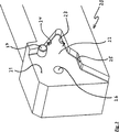
Die Wendeschneidplatte weist vier sich in
Dabei hat der in der Draufsicht achteckige Hauptteil
Der lichte Abstand der jeweiligen Schneidkante
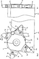
In
Die Flanke
Weiter erkannt man auch in der Seitenfläche
In
Für Zwecke der ursprünglichen Offenbarung wird darauf hingewiesen, dass sämtliche Merkmale, wie sie sich aus der vorliegenden Beschreibung, den Zeichnungen und den abhängigen Ansprüchen für einen Fachmann erschließen, auch wenn sie konkret nur im Zusammenhang mit bestimmten weiteren Merkmalen beschrieben wurden, sowohl einzeln als auch in beliebigen Zusammenstellungen mit anderen der hier offenbarten Merkmale oder Merkmalsgruppen kombinierbar sind, soweit dies nicht ausdrücklich ausgeschlossen wurde oder technische Gegebenheiten derartige Kombinationen unmöglich oder sinnlos machen. Auf die umfassende, explizite Darstellung sämtlicher denkbarer Merkmalskombinationen und die Betonung der Unabhängigkeit der einzelnen Merkmale voneinander wird hier nur der Kürze und der Lesbarkeit der Beschreibung wegen verzichtet.For purposes of the original disclosure, it is to be understood that all such features as will become apparent to those skilled in the art from the present description, drawings and dependent claims, even though they have been specifically described only in connection with certain further features, both individually and can be combined in any combination with other features or feature groups disclosed herein, unless this has been expressly excluded or technical Conditions make such combinations impossible or pointless. On the comprehensive, explicit representation of all conceivable combinations of features and the emphasis on the independence of the individual characteristics of each other is omitted here only for the sake of brevity and readability of the description.
ZITATE ENTHALTEN IN DER BESCHREIBUNG QUOTES INCLUDE IN THE DESCRIPTION
Diese Liste der vom Anmelder aufgeführten Dokumente wurde automatisiert erzeugt und ist ausschließlich zur besseren Information des Lesers aufgenommen. Die Liste ist nicht Bestandteil der deutschen Patent- bzw. Gebrauchsmusteranmeldung. Das DPMA übernimmt keinerlei Haftung für etwaige Fehler oder Auslassungen.This list of the documents listed by the applicant has been generated automatically and is included solely for the better information of the reader. The list is not part of the German patent or utility model application. The DPMA assumes no liability for any errors or omissions.
Zitierte PatentliteraturCited patent literature
- EP 1136158 A1 [0004] EP 1136158 A1 [0004]
Claims (19)
Priority Applications (7)
| Application Number | Priority Date | Filing Date | Title |
|---|---|---|---|
| DE102011007076A DE102011007076A1 (en) | 2011-04-08 | 2011-04-08 | Indexable insert and indexable insert holder |
| CN201280017398.9A CN103459069B (en) | 2011-04-08 | 2012-03-30 | Indexable cutting inserts and Indexable cutting inserts frame |
| US13/985,492 US9457409B2 (en) | 2011-04-08 | 2012-03-30 | Indexable cutting insert and indexable cutting insert holder |
| EP12714624.9A EP2694236B1 (en) | 2011-04-08 | 2012-03-30 | Indexable cutting insert and indexable insert holder |
| JP2014503094A JP2014509956A (en) | 2011-04-08 | 2012-03-30 | Blade-tip replaceable insert and blade-tip replaceable insert holder |
| PCT/EP2012/055884 WO2012136600A1 (en) | 2011-04-08 | 2012-03-30 | Indexable cutting insert and indexable cutting insert holder |
| KR1020137025425A KR101819786B1 (en) | 2011-04-08 | 2012-03-30 | Indexable cutting insert and indexable cutting insert holder |
Applications Claiming Priority (1)
| Application Number | Priority Date | Filing Date | Title |
|---|---|---|---|
| DE102011007076A DE102011007076A1 (en) | 2011-04-08 | 2011-04-08 | Indexable insert and indexable insert holder |
Publications (1)
| Publication Number | Publication Date |
|---|---|
| DE102011007076A1 true DE102011007076A1 (en) | 2012-10-11 |
Family
ID=45974279
Family Applications (1)
| Application Number | Title | Priority Date | Filing Date |
|---|---|---|---|
| DE102011007076A Withdrawn DE102011007076A1 (en) | 2011-04-08 | 2011-04-08 | Indexable insert and indexable insert holder |
Country Status (7)
| Country | Link |
|---|---|
| US (1) | US9457409B2 (en) |
| EP (1) | EP2694236B1 (en) |
| JP (1) | JP2014509956A (en) |
| KR (1) | KR101819786B1 (en) |
| CN (1) | CN103459069B (en) |
| DE (1) | DE102011007076A1 (en) |
| WO (1) | WO2012136600A1 (en) |
Cited By (4)
| Publication number | Priority date | Publication date | Assignee | Title |
|---|---|---|---|---|
| US20150290717A1 (en) * | 2014-04-10 | 2015-10-15 | Iscar, Ltd. | Cutting tool and cutting insert having exactly four cutting portions therefor |
| WO2018172462A1 (en) * | 2017-03-24 | 2018-09-27 | Ceramtec Gmbh | Star-type indexable cutting insert and tool system |
| EP3702074A1 (en) * | 2019-03-01 | 2020-09-02 | Whizcut of Sweden AB | Indexable cutting insert |
| JP6961151B1 (en) * | 2021-03-23 | 2021-11-05 | 株式会社タンガロイ | Turning tool |
Families Citing this family (18)
| Publication number | Priority date | Publication date | Assignee | Title |
|---|---|---|---|---|
| EP2664399B1 (en) * | 2012-05-15 | 2017-01-04 | VARGUS Ltd. | Cutting tool |
| US9421622B2 (en) * | 2014-01-14 | 2016-08-23 | Iscar, Ltd. | Indexable central drill insert and cutting tool therefor |
| JP5988010B2 (en) * | 2014-03-14 | 2016-09-07 | 株式会社タンガロイ | Cutting inserts, tool bodies and cutting tools |
| DE102014006054A1 (en) | 2014-04-25 | 2015-10-29 | Iscar Ltd. | Cutting tool and cutting insert with exactly four Schneidabschitten for it |
| US10160040B2 (en) * | 2015-11-18 | 2018-12-25 | Iscar, Ltd. | Cutting tool and triangular-shaped indexable cutting insert therefor |
| JP6616176B2 (en) * | 2015-12-24 | 2019-12-04 | 京セラ株式会社 | Cutting tools |
| US9901986B2 (en) | 2016-02-15 | 2018-02-27 | Iscar, Ltd. | Swiss turning insert with chip former arrangement comprising upwardly extending ridge |
| DE102016109670A1 (en) * | 2016-05-25 | 2017-11-30 | Hartmetall-Werkzeugfabrik Paul Horn Gmbh | Cutting plate and tool for machining |
| US10010942B2 (en) * | 2016-06-20 | 2018-07-03 | Iscar, Ltd. | Cutting tool and cutting insert having a deep blind opening |
| US10076794B2 (en) | 2016-07-11 | 2018-09-18 | Iscar, Ltd. | Star-shaped cutting insert for a front and back chamfering rotary milling cutter |
| US10363722B2 (en) * | 2017-03-23 | 2019-07-30 | Iscar, Ltd. | Blade-shaped cutting insert and cutting tool therefor |
| JP6447892B1 (en) * | 2017-06-23 | 2019-01-09 | 株式会社タンガロイ | Cutting tools |
| CN109570629B (en) * | 2017-09-28 | 2020-09-25 | 株式会社泰珂洛 | Cutting tool |
| KR102377066B1 (en) | 2020-12-21 | 2022-03-21 | 한국야금 주식회사 | Cutting insert and Tool mounted withthere |
| JP6882726B1 (en) * | 2021-01-05 | 2021-06-02 | 株式会社タンガロイ | holder |
| US11806793B2 (en) | 2021-11-03 | 2023-11-07 | Iscar, Ltd. | Cutting insert having laterally spaced apart, longitudinally extending wedge abutment surfaces, tool holder and cutting tool |
| CN116175288B (en) * | 2023-04-27 | 2023-08-25 | 中国机械总院集团宁波智能机床研究院有限公司 | Indexable blade automatic positioning device |
| CN116571771B (en) * | 2023-07-12 | 2024-02-02 | 赣州澳克泰工具技术有限公司 | Boring cutter with a plurality of cutting parts |
Citations (6)
| Publication number | Priority date | Publication date | Assignee | Title |
|---|---|---|---|---|
| GB2070472A (en) * | 1980-02-26 | 1981-09-09 | Brock & Co Ltd L & Ti | Disposable tool tip for cutting a screw-thread or groove |
| US5529440A (en) * | 1991-05-31 | 1996-06-25 | Nya Scandinavian Tool Systems Ab | Cut-off and slotting insert having cutting edges on four symmetrical corners |
| JP2001062624A (en) * | 1999-08-26 | 2001-03-13 | Toshiba Tungaloy Co Ltd | Throwaway tip |
| EP1136158A1 (en) | 2000-03-16 | 2001-09-26 | Sandvik AB | Cutting insert holder for turning tools and grooving insert therefor |
| US20070231089A1 (en) * | 2006-03-30 | 2007-10-04 | Iscar Ltd. | Cutting Tool |
| WO2009082327A1 (en) * | 2007-12-20 | 2009-07-02 | Seco Tools Ab | An indexable turning insert and a cutting tool comprising such an insert |
Family Cites Families (16)
| Publication number | Priority date | Publication date | Assignee | Title |
|---|---|---|---|---|
| DE2130814A1 (en) | 1971-06-22 | 1972-12-28 | Ambo Stahl Ges Gerhard Sevenic | Cutting tool for the machining of workpieces |
| AU524391B2 (en) | 1978-06-02 | 1982-09-16 | Kennametal Inc. | Cutting insert and holder |
| US4360297A (en) | 1978-06-02 | 1982-11-23 | Kennametal Inc. | Cutting insert |
| SE454330B (en) * | 1984-03-28 | 1988-04-25 | Santrade Ltd | REQUEST FOR TEAM DISPOSAL PROCESSING |
| JP2531608B2 (en) | 1984-06-26 | 1996-09-04 | 株式会社東芝 | Method for manufacturing semiconductor device |
| SE463752B (en) * | 1989-05-31 | 1991-01-21 | Reinar Schmidt | EXCHANGABLE SHOULD BE WIRED AND SAVING |
| US5308197A (en) * | 1990-01-23 | 1994-05-03 | Threading Systems, Inc. | Machining apparatus |
| US5163788A (en) * | 1991-01-10 | 1992-11-17 | Gte Valenite Corporation | Rotary slotting tool having staggered cutting elements |
| US5607263A (en) * | 1993-04-14 | 1997-03-04 | Zettl Gmbh Cnc Prazisions-Und Sonderwerkzuege | Cutting tool |
| IL152161A (en) * | 2002-02-19 | 2008-03-20 | Jacob Friedman | Metal cutting tool |
| JP3948708B2 (en) * | 2002-02-21 | 2007-07-25 | 株式会社タンガロイ | Grooving tool |
| EP2131980A1 (en) * | 2007-02-28 | 2009-12-16 | CeramTec AG | Insert seat adapter |
| IL185047A (en) * | 2007-08-05 | 2011-09-27 | Iscar Ltd | Cutting tool |
| US8192114B2 (en) * | 2009-02-09 | 2012-06-05 | Hsin-Tien Chang | Combination of center drill and drill holding tool |
| IL208826A (en) | 2010-10-20 | 2016-02-29 | Iscar Ltd | Cutting tool and cutting insert therefor |
| US9174279B2 (en) * | 2011-12-14 | 2015-11-03 | Iscar, Ltd. | Indexable cutting insert and cutting tool therefor |
-
2011
- 2011-04-08 DE DE102011007076A patent/DE102011007076A1/en not_active Withdrawn
-
2012
- 2012-03-30 EP EP12714624.9A patent/EP2694236B1/en active Active
- 2012-03-30 JP JP2014503094A patent/JP2014509956A/en active Pending
- 2012-03-30 WO PCT/EP2012/055884 patent/WO2012136600A1/en active Application Filing
- 2012-03-30 CN CN201280017398.9A patent/CN103459069B/en active Active
- 2012-03-30 US US13/985,492 patent/US9457409B2/en active Active
- 2012-03-30 KR KR1020137025425A patent/KR101819786B1/en active IP Right Grant
Patent Citations (6)
| Publication number | Priority date | Publication date | Assignee | Title |
|---|---|---|---|---|
| GB2070472A (en) * | 1980-02-26 | 1981-09-09 | Brock & Co Ltd L & Ti | Disposable tool tip for cutting a screw-thread or groove |
| US5529440A (en) * | 1991-05-31 | 1996-06-25 | Nya Scandinavian Tool Systems Ab | Cut-off and slotting insert having cutting edges on four symmetrical corners |
| JP2001062624A (en) * | 1999-08-26 | 2001-03-13 | Toshiba Tungaloy Co Ltd | Throwaway tip |
| EP1136158A1 (en) | 2000-03-16 | 2001-09-26 | Sandvik AB | Cutting insert holder for turning tools and grooving insert therefor |
| US20070231089A1 (en) * | 2006-03-30 | 2007-10-04 | Iscar Ltd. | Cutting Tool |
| WO2009082327A1 (en) * | 2007-12-20 | 2009-07-02 | Seco Tools Ab | An indexable turning insert and a cutting tool comprising such an insert |
Cited By (7)
| Publication number | Priority date | Publication date | Assignee | Title |
|---|---|---|---|---|
| US20150290717A1 (en) * | 2014-04-10 | 2015-10-15 | Iscar, Ltd. | Cutting tool and cutting insert having exactly four cutting portions therefor |
| US9421615B2 (en) * | 2014-04-10 | 2016-08-23 | Iscar, Ltd. | Cutting tool and cutting insert having exactly four cutting portions therefor |
| WO2018172462A1 (en) * | 2017-03-24 | 2018-09-27 | Ceramtec Gmbh | Star-type indexable cutting insert and tool system |
| EP3702074A1 (en) * | 2019-03-01 | 2020-09-02 | Whizcut of Sweden AB | Indexable cutting insert |
| WO2020178214A1 (en) * | 2019-03-01 | 2020-09-10 | Whizcut Of Sweden Ab | Indexable cutting insert |
| JP6961151B1 (en) * | 2021-03-23 | 2021-11-05 | 株式会社タンガロイ | Turning tool |
| JP2022147572A (en) * | 2021-03-23 | 2022-10-06 | 株式会社タンガロイ | Lathe tool |
Also Published As
| Publication number | Publication date |
|---|---|
| KR20140013002A (en) | 2014-02-04 |
| KR101819786B1 (en) | 2018-01-17 |
| EP2694236A1 (en) | 2014-02-12 |
| US9457409B2 (en) | 2016-10-04 |
| WO2012136600A1 (en) | 2012-10-11 |
| JP2014509956A (en) | 2014-04-24 |
| CN103459069B (en) | 2016-05-18 |
| CN103459069A (en) | 2013-12-18 |
| EP2694236B1 (en) | 2021-01-27 |
| US20140050542A1 (en) | 2014-02-20 |
Similar Documents
| Publication | Publication Date | Title |
|---|---|---|
| DE102011007076A1 (en) | Indexable insert and indexable insert holder | |
| EP2032292B1 (en) | Indexable insert | |
| EP0781382B1 (en) | Countersunk head screw | |
| DE102006011581B4 (en) | Cutting insert and milling tool | |
| EP2846954B1 (en) | Indexable insert for shoulder milling cutter and shoulder milling cutter with mounting cutouts for indexable inserts | |
| DE19980707B4 (en) | Composite cutting tool and cutting insert for it | |
| EP1675699B1 (en) | Cutting element, particularly for parting and longitudinal turning | |
| DE102011105978B4 (en) | Indexable insert and face milling cutter with indexable insert | |
| EP1640095B1 (en) | Milling tool, especially thread milling cutter | |
| DE202013004041U1 (en) | Cutting tool, cutting insert and tool holder | |
| DE102007022535A1 (en) | Eight cutting insert and tool holder for this | |
| DE1552296B2 (en) | CUTTING TOOL | |
| DE112013006433T5 (en) | Cutting tool with cutting insert, which has non-adjacent side edges | |
| DE112014002524T5 (en) | Cutting insert with a rearwardly offset cutting edge and cutting tool | |
| WO2010069541A1 (en) | Reamer, cutter plates therefor and method for adjusting the machining diameter of a reamer of this type | |
| DE102011053760A1 (en) | Grooving plate and clamp holder with four-point systems | |
| DE10305854B4 (en) | Square cutting insert for milling cutters with negative radial angle of the cutting edges for the three-dimensional milling from the solid | |
| EP3362213B1 (en) | Cutting insert, tool holder, and tool for machining a workpiece | |
| DE102005019945A1 (en) | Cutting tool for turning lathe, has clips with two edges running parallel to each other, and profile provided in area of both edges, where profiles of edges in one section are different from profiles of edges in other section | |
| EP2394763B1 (en) | Cutting plate and saw blade with a number of such cutting plates | |
| DE102016109452A1 (en) | Cutting plate for a milling tool and milling tool | |
| DE202005019134U1 (en) | Cutting tool for turning lathe, has clips with two edges running parallel to each other, and profile provided in area of both edges, where profiles of edges in one section are different from profiles of edges in other section | |
| DE102015014907A1 (en) | Cutting tool and triangular indexable cutting insert for this purpose | |
| DE102007019666B4 (en) | indexable milling | |
| DE1552296C (en) | Cutting tool |
Legal Events
| Date | Code | Title | Description |
|---|---|---|---|
| R163 | Identified publications notified | ||
| R012 | Request for examination validly filed | ||
| R119 | Application deemed withdrawn, or ip right lapsed, due to non-payment of renewal fee |