DE102011001663B4 - System for monitoring relative displacement of components - Google Patents
System for monitoring relative displacement of components Download PDFInfo
- Publication number
- DE102011001663B4 DE102011001663B4 DE102011001663.5A DE102011001663A DE102011001663B4 DE 102011001663 B4 DE102011001663 B4 DE 102011001663B4 DE 102011001663 A DE102011001663 A DE 102011001663A DE 102011001663 B4 DE102011001663 B4 DE 102011001663B4
- Authority
- DE
- Germany
- Prior art keywords
- bragg grating
- fiber bragg
- relative displacement
- end winding
- components
- Prior art date
- Legal status (The legal status is an assumption and is not a legal conclusion. Google has not performed a legal analysis and makes no representation as to the accuracy of the status listed.)
- Expired - Fee Related
Links
- 238000006073 displacement reaction Methods 0.000 title claims abstract description 80
- 238000012544 monitoring process Methods 0.000 title claims abstract description 14
- 239000000835 fiber Substances 0.000 claims abstract description 111
- 238000004804 winding Methods 0.000 claims abstract description 61
- 230000005855 radiation Effects 0.000 claims abstract description 21
- 238000000034 method Methods 0.000 claims abstract description 6
- 239000000463 material Substances 0.000 claims description 10
- 239000000853 adhesive Substances 0.000 claims description 5
- 230000001070 adhesive effect Effects 0.000 claims description 5
- 238000013461 design Methods 0.000 description 18
- 239000013307 optical fiber Substances 0.000 description 14
- 238000005259 measurement Methods 0.000 description 9
- 238000011960 computer-aided design Methods 0.000 description 6
- 230000008901 benefit Effects 0.000 description 5
- 230000008859 change Effects 0.000 description 3
- 230000005520 electrodynamics Effects 0.000 description 2
- 238000009413 insulation Methods 0.000 description 2
- 238000004519 manufacturing process Methods 0.000 description 2
- 239000002184 metal Substances 0.000 description 2
- 230000003287 optical effect Effects 0.000 description 2
- 238000001228 spectrum Methods 0.000 description 2
- 239000004593 Epoxy Substances 0.000 description 1
- 230000009471 action Effects 0.000 description 1
- WYTGDNHDOZPMIW-RCBQFDQVSA-N alstonine Natural products C1=CC2=C3C=CC=CC3=NC2=C2N1C[C@H]1[C@H](C)OC=C(C(=O)OC)[C@H]1C2 WYTGDNHDOZPMIW-RCBQFDQVSA-N 0.000 description 1
- 230000015556 catabolic process Effects 0.000 description 1
- 229920001940 conductive polymer Polymers 0.000 description 1
- 238000001514 detection method Methods 0.000 description 1
- 230000000694 effects Effects 0.000 description 1
- 230000005672 electromagnetic field Effects 0.000 description 1
- 239000011888 foil Substances 0.000 description 1
- 239000003292 glue Substances 0.000 description 1
- 238000011835 investigation Methods 0.000 description 1
- 238000012986 modification Methods 0.000 description 1
- 230000004048 modification Effects 0.000 description 1
- 230000010355 oscillation Effects 0.000 description 1
- 239000002861 polymer material Substances 0.000 description 1
- 230000002028 premature Effects 0.000 description 1
- 230000008569 process Effects 0.000 description 1
- 230000004044 response Effects 0.000 description 1
- 229920001187 thermosetting polymer Polymers 0.000 description 1
Images
Classifications
-
- G—PHYSICS
- G01—MEASURING; TESTING
- G01B—MEASURING LENGTH, THICKNESS OR SIMILAR LINEAR DIMENSIONS; MEASURING ANGLES; MEASURING AREAS; MEASURING IRREGULARITIES OF SURFACES OR CONTOURS
- G01B11/00—Measuring arrangements characterised by the use of optical techniques
- G01B11/02—Measuring arrangements characterised by the use of optical techniques for measuring length, width or thickness
-
- G—PHYSICS
- G01—MEASURING; TESTING
- G01B—MEASURING LENGTH, THICKNESS OR SIMILAR LINEAR DIMENSIONS; MEASURING ANGLES; MEASURING AREAS; MEASURING IRREGULARITIES OF SURFACES OR CONTOURS
- G01B11/00—Measuring arrangements characterised by the use of optical techniques
- G01B11/16—Measuring arrangements characterised by the use of optical techniques for measuring the deformation in a solid, e.g. optical strain gauge
- G01B11/18—Measuring arrangements characterised by the use of optical techniques for measuring the deformation in a solid, e.g. optical strain gauge using photoelastic elements
-
- H—ELECTRICITY
- H02—GENERATION; CONVERSION OR DISTRIBUTION OF ELECTRIC POWER
- H02K—DYNAMO-ELECTRIC MACHINES
- H02K11/00—Structural association of dynamo-electric machines with electric components or with devices for shielding, monitoring or protection
- H02K11/20—Structural association of dynamo-electric machines with electric components or with devices for shielding, monitoring or protection for measuring, monitoring, testing, protecting or switching
-
- G—PHYSICS
- G01—MEASURING; TESTING
- G01B—MEASURING LENGTH, THICKNESS OR SIMILAR LINEAR DIMENSIONS; MEASURING ANGLES; MEASURING AREAS; MEASURING IRREGULARITIES OF SURFACES OR CONTOURS
- G01B11/00—Measuring arrangements characterised by the use of optical techniques
- G01B11/16—Measuring arrangements characterised by the use of optical techniques for measuring the deformation in a solid, e.g. optical strain gauge
- G01B11/165—Measuring arrangements characterised by the use of optical techniques for measuring the deformation in a solid, e.g. optical strain gauge by means of a grating deformed by the object
-
- G—PHYSICS
- G01—MEASURING; TESTING
- G01L—MEASURING FORCE, STRESS, TORQUE, WORK, MECHANICAL POWER, MECHANICAL EFFICIENCY, OR FLUID PRESSURE
- G01L1/00—Measuring force or stress, in general
- G01L1/24—Measuring force or stress, in general by measuring variations of optical properties of material when it is stressed, e.g. by photoelastic stress analysis using infrared, visible light, ultraviolet
- G01L1/242—Measuring force or stress, in general by measuring variations of optical properties of material when it is stressed, e.g. by photoelastic stress analysis using infrared, visible light, ultraviolet the material being an optical fibre
- G01L1/246—Measuring force or stress, in general by measuring variations of optical properties of material when it is stressed, e.g. by photoelastic stress analysis using infrared, visible light, ultraviolet the material being an optical fibre using integrated gratings, e.g. Bragg gratings
-
- G—PHYSICS
- G01—MEASURING; TESTING
- G01R—MEASURING ELECTRIC VARIABLES; MEASURING MAGNETIC VARIABLES
- G01R31/00—Arrangements for testing electric properties; Arrangements for locating electric faults; Arrangements for electrical testing characterised by what is being tested not provided for elsewhere
- G01R31/34—Testing dynamo-electric machines
-
- H—ELECTRICITY
- H02—GENERATION; CONVERSION OR DISTRIBUTION OF ELECTRIC POWER
- H02K—DYNAMO-ELECTRIC MACHINES
- H02K11/00—Structural association of dynamo-electric machines with electric components or with devices for shielding, monitoring or protection
- H02K11/20—Structural association of dynamo-electric machines with electric components or with devices for shielding, monitoring or protection for measuring, monitoring, testing, protecting or switching
- H02K11/21—Devices for sensing speed or position, or actuated thereby
- H02K11/22—Optical devices
Landscapes
- Engineering & Computer Science (AREA)
- Physics & Mathematics (AREA)
- General Physics & Mathematics (AREA)
- Microelectronics & Electronic Packaging (AREA)
- Power Engineering (AREA)
- Length Measuring Devices By Optical Means (AREA)
- Optical Transform (AREA)
- Manufacture Of Motors, Generators (AREA)
Abstract
System (100) zum Überwachen einer relativen Verschiebung (124) eines Paares von Wickelkopfkomponenten (102, 104), wobei das Verfahren (100) aufweist:eine an dem Paar der Wickelkopfkomponenten (102, 104) befestigte Struktur (110);ein Faser-Bragg-Gitter (116), das auf einer nicht-gekrümmten Oberfläche (126) der Struktur (110) befestigt ist, wobei das Faser-Bragg-Gitter (116) dafür konfiguriert ist, einfallende Strahlung zu reflektieren, wobei die reflektierte Strahlung eine Spitzenintensität bei einer entsprechenden Wellenlänge auf der Basis einer Dehnung (122) des Faser-Bragg-Gitters (116) hat, wobei sich die Dehnung (122) des Faser-Bragg-Gitters (116) aus einer Dehnung der Struktur (110) aufgrund der relativen Verschiebung (124) des Paares der Wickelkopfkomponenten (102) ergibt;wobei die Struktur (110) so konfiguriert ist, dass die von der Struktur (110) erzeugte Dehnung eine Größe der Dehnung (122) des Faser-Bragg-Gitters (116) in einem vorbestimmten Bereich über einer Spanne der relativen Verschiebung (124) des Paares der Wickelkopfkomponenten (102) begrenzt.A system (100) for monitoring relative displacement (124) of a pair of end winding components (102, 104), the method (100) comprising: a structure (110) attached to the pair of end winding components (102, 104); Bragg grating (116) mounted on a non-curved surface (126) of the structure (110), the fiber Bragg grating (116) configured to reflect incident radiation, the reflected radiation having a peak intensity at a corresponding wavelength on the basis of an expansion (122) of the fiber Bragg grating (116), the expansion (122) of the fiber Bragg grating (116) being derived from an expansion of the structure (110) due to the relative Displacement (124) of the pair of end winding components (102); wherein the structure (110) is configured such that the strain created by the structure (110) is an amount of the strain (122) of the fiber Bragg grating (116) in a predetermined range over a range of the rela tive displacement (124) of the pair of end winding components (102) is limited.
Description
Hintergrundbackground
Die Erfindung betrifft im Wesentlichen ein System zum Überwachen einer relativen Verschiebung von Komponenten, und insbesondere ein System zum Überwachen einer relativen Verschiebung von Wickelkopfkomponenten eines Generators.The invention relates generally to a system for monitoring a relative displacement of components, and more particularly to a system for monitoring a relative displacement of end-winding components of a generator.
Rotationsmaschinen, wie z.B. von Dampfturbinen oder Gasturbinen angetriebene elektrische Generatoren, haben die Fähigkeit, mehrere Tausend Ampere Strom in ihren Statorwicklungen zu leiten. Die Statorwicklungen weisen im Wesentlichen leitende Stangen auf, die in entsprechenden Schlitzen in einem Statorkern befestigt sind und Wickelköpfe, die sich über den Statorkern hinaus erstrecken. Die Wickelkopfkomponenten sind elektrodynamischen und mechanischen Kräften unterworfen, die eine Verschiebung der Wickelköpfe bewirken. Elektrodynamische Kräfte werden beispielsweise durch einen die Wickelköpfe während des Startvorgangs und Spitzenlastzuständen durchfließenden hohen Strom bewirkt. Mechanische Kräfte werden durch die normale mechanische Wärmeausdehnung und Schwingungen der Rotationsmaschinen verursacht. Es hat sich herausgestellt, dass eine übermäßige Verschiebung der Wickelköpfe verschiedene unerwünschte Effekte einschließlich derjenigen hat, dass die Wicklungsisolation in den Wickelköpfen zerstört werden kann, was zu einem Isolationszusammenbruch zwischen den Wickelköpfen führt, und dass Wickelköpfe einem Verschleiß aufgrund elektromechanischer Kräfte unterliegen, die zu einem vorzeitigen Ausfall der Rotationsmaschine führen. Es besteht ein Bedarf im Fachgebiet, den Wickelkopfstatus zu überwachen, und es ist eine frühzeitige und genaue Detektion einer Wickelkopflockerung erwünscht.Rotary machines, such as electric generators powered by steam turbines or gas turbines, have the ability to conduct several thousand amps of current in their stator windings. The stator windings have essentially conductive rods that are secured in corresponding slots in a stator core and end windings that extend beyond the stator core. The winding head components are subject to electrodynamic and mechanical forces which cause the winding heads to shift. Electrodynamic forces are caused, for example, by a high current flowing through the end windings during the starting process and peak load conditions. Mechanical forces are caused by the normal mechanical thermal expansion and vibration of rotating machinery. It has been found that excessive displacement of the winding heads has various undesirable effects including that the winding insulation in the winding heads can be destroyed, resulting in insulation breakdown between the winding heads, and that winding heads are subject to wear due to electromechanical forces that lead to a premature failure of the rotary machine. There is a need in the art to monitor winding head status and early and accurate detection of winding head looseness is desirable.
Es wurden bereits herkömmliche Systeme vorgeschlagen, um die Verschiebung von Wickelkopfkomponenten zu detektieren. Jedoch haben Elektronik-basierende Systeme Metallkomponenten, die aufgrund der hohen elektromagnetischen Felder nicht in der Nähe der Wickelkopfkomponenten genutzt werden können, und optische Schwingungsmesssysteme sind für eine kosteneffektive Nutzung zu teuer. Somit wäre es vorteilhaft, ein Überwachungssystem bereitzustellen, welches sich mit diesen Nachteilen befasst.Conventional systems have been proposed to detect the displacement of end winding components. However, electronics-based systems have metal components that cannot be used in the vicinity of the end-winding components due to the high electromagnetic fields, and optical vibration measurement systems are too expensive to be used cost-effectively. Thus, it would be advantageous to provide a monitoring system that addresses these drawbacks.
KurzbeschreibungBrief description
Gemäß einer Beispielausführungsform wird ein System für die Überwachung einer relativen Verschiebung eines Paares von Wickelkopfkomponenten bereitgestellt. Das System enthält eine auf den Wickelkopfkomponenten befestigte Struktur. Das System enthält ferner ein auf einer nicht-gekrümmten Oberfläche der Struktur befestigtes Faser-Bragg-Gitter, wobei das Faser-Bragg-Gitter dafür konfiguriert ist, einfallende Strahlung mit einer Spitzenintensität bei einer entsprechenden Wellenlänge auf der Basis einer Dehnung des Faser-Bragg-Gitters zu reflektieren. Die Struktur ist so konfiguriert, dass die von der Struktur erzeugte Dehnung eine Größe der Dehnung des Faser-Bragg-Gitters auf einen vorbestimmten Bereich über eine Spanne der relativen Verschiebung des Paares der Wickelkopfkomponenten begrenzt.In accordance with an example embodiment, a system is provided for monitoring relative displacement of a pair of end winding components. The system includes a structure attached to the end winding components. The system further includes a fiber Bragg grating mounted on a non-curved surface of the structure, the fiber Bragg grating configured to receive incident radiation having a peak intensity at a corresponding wavelength based on a strain of the fiber Bragg grating. Reflect grating. The structure is configured such that the strain created by the structure limits an amount of strain of the fiber Bragg grating to a predetermined range over a span of the relative displacement of the pair of end winding components.
Gemäß einer weiteren hierin offengelegten Beispielausführungsform wird eine Energieerzeugungsvorrichtung bereitgestellt. Die Energieerzeugungsvorrichtung enthält ein Paar von Wickelkopfkomponenten, die so konfiguriert sind, dass sie einer relativen Verschiebung während eines Betriebs der Energieerzeugungsvorrichtung zu unterliegen. Die Energieerzeugungsvorrichtung enthält ferner eine auf den Wickelkopfkomponenten befestigte Struktur und ein auf einer nicht-gekrümmten Oberfläche der Struktur befestigtes Faser-Bragg-Gitter. Das Faser-Bragg-Gitter ist dafür konfiguriert, einfallende Strahlung mit einer Spitzenintensität bei einer entsprechenden Wellenlänge auf der Basis einer Dehnung des Faser-Bragg-Gitters zu reflektieren. Die Dehnung des Faser-Bragg-Gitters ergibt sich aus einer Dehnung der Struktur aufgrund der relativen Verschiebung des Paares der Wickelkopfkomponenten. Die Struktur ist so konfiguriert, dass die von der Struktur erzeugte Dehnung eine Größe der Dehnung des Faser-Bragg-Gitters auf einen vorbestimmten Bereich über eine Spanne der relativen Verschiebung des Paares der Wickelkopfkomponenten begrenzt.According to another example embodiment disclosed herein, a power generating device is provided. The power generating device includes a pair of end winding components that are configured to undergo relative displacement during operation of the power generating device. The power generating device further includes a structure mounted on the end winding components and a fiber Bragg grating mounted on a non-curved surface of the structure. The fiber Bragg grating is configured to reflect incident radiation with a peak intensity at a corresponding wavelength based on an expansion of the fiber Bragg grating. the Expansion of the fiber Bragg grating results from expansion of the structure due to the relative displacement of the pair of end winding components. The structure is configured such that the strain created by the structure limits an amount of strain of the fiber Bragg grating to a predetermined range over a span of the relative displacement of the pair of end winding components.
FigurenlisteFigure list
Diese und weitere Merkmale, Aspekte und Vorteile der vorliegenden Erfindung werden besser verständlich, wenn die nachstehende detaillierte Beschreibung unter Bezugnahme auf die beigefügten Zeichnungen gelesen wird, in welchen gleiche Bezugszeichen gleiche Teile durchgängig durch die Zeichnungen bezeichnen, wobei:
-
1 eine Teilseitenquerschnittsansicht einer Struktur und eines auf einem Paar von Wickelkopfkomponenten befestigten Faser-Bragg-Gitters gemäß einer Beispielausführungsform der Erfindung ist; -
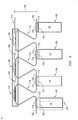
2 eine Teilseitenquerschnittsansicht von mehreren Strukturen und auf den Wickelkopfkomponenten befestigten Faser-Bragg-Gittern gemäß einer weiteren Beispielausführungsform der Erfindung ist; -
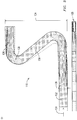
3 eine Teilseitenquerschnittsansicht der Struktur in1 während einer Entwurfsphase ist; -
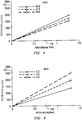
4 eine graphische Darstellung einer Dehnung des Faser-Bragg-Gitters über einer Verschiebung der Wickelkopfkomponenten für entsprechende Höhen und eine feste Dicke in der in3 dargestellten Struktur während der Entwurfsphase ist; -
5 eine graphische Darstellung einer Dehnung des Faser-Bragg-Gitters über einer Verschiebung der Wickelkopfkomponenten für entsprechende Dicken und eine feste Höhe in der in3 dargestellten Struktur während der Entwurfsphase ist; und -
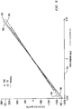
6 eine graphische Darstellung einer Dehnung des Faser-Bragg-Gitters über einer Verschiebungsspanne der in1 dargestellten Kopfwicklungskomponenten ist.
-
1 Figure 13 is a partial side cross-sectional view of a structure and a fiber Bragg grating mounted on a pair of end-turn components in accordance with an example embodiment of the invention; -
2 Figure 3 is a partial side cross-sectional view of multiple structures and fiber Bragg gratings mounted on end-turn components in accordance with another example embodiment of the invention; -
3 FIG. 3 is a partial side cross-sectional view of the structure in FIG1 is during a design phase; -
4th a graphical representation of an expansion of the fiber Bragg grating versus a displacement of the end winding components for corresponding heights and a fixed thickness in the in3 is the structure shown during the design phase; -
5 a graphical representation of an elongation of the fiber Bragg grating versus a displacement of the end winding components for corresponding thicknesses and a fixed height in the in3 is the structure shown during the design phase; and -
6th a graphical representation of an elongation of the fiber Bragg grating over a range of displacement of the in1 is illustrated head winding components.
Detaillierte BeschreibungDetailed description
Beispielausführungsformen der Erfindung werden im Zusammenhang von Stator-Wickelkopf-Überwachungssystemen unter Verwendung von faseroptischen Messkabeln für die Messung einer relativen Verschiebung der Wickelkopfkomponenten einschließlich, jedoch nicht darauf beschränkt, von Unterstützungs- oder Verbindungskomponenten, die direkt oder indirekt Statorwickelköpfe unterstützen oder damit verbunden sind, einschließlich, jedoch nicht darauf beschränkt, Verbindungsringen und Statorstangen beschrieben. Eine relative Verschiebung zwischen den Wickelkopfkomponenten ist ein Hinweis auf den Statorwickelkopf-Status. „Relative Verschiebung“ hierin bezieht sich auf eine Verschiebung eines Abstandes zwischen zwei Wickelkopfkomponenten. Die zwei Wickelkopfkomponenten können direkt nebeneinanderliegen, oder können durch eine oder mehrere Wickelkopfkomponenten dazwischen getrennt sein. So wie hierin verwendet, bezeichnen die Begriffe „ein, einer, eine, eines“ und „der, die, das“ keine Einschränkung einer Menge, sondern geben lediglich das Vorhandensein von wenigstens einem der Elemente an. In ähnlicher Weise bedeutet „zwei Wickelkopfkomponenten“, so wie hierin verwendet, wenigstens zwei Wickelkopfkomponenten.Example embodiments of the invention are used in the context of stator end winding monitoring systems using fiber optic measurement cables for measuring relative displacement of end winding components including, but not limited to, support or connection components that directly or indirectly support or are connected to stator end turns, including but not limited to connecting rings and stator bars. Relative displacement between the end winding components is an indication of the stator end winding status. "Relative displacement" herein refers to a displacement of a distance between two end winding components. The two end winding components can lie directly next to one another, or can be separated therebetween by one or more end winding components. As used herein, the terms "a, an, an," and "the, the, that" do not denote a limitation on an amount, but merely indicate the presence of at least one of the elements. Similarly, as used herein, “two end winding components” means at least two end winding components.
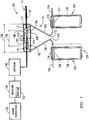
Gemäß Darstellung in
Man erkennt, dass die Fähigkeit, das Faser-Bragg-Gitter
Man erkennt ferner, dass durch die Auslegung der Struktur mit einer nicht-gekrümmten Oberfläche für die Befestigung des Faser-Bragg-Gitters die Dehnung an allen Abschnitten des Faser-Bragg-Gitters im Wesentlichen dieselbe ist. Dieses ist vorteilhaft, da die entsprechende Wellenlänge der eine Spitzenintensität habenden reflektierten Strahlung unzweideutig ist. Wenn unterschiedliche Abschnitte des Faser-Bragg-Gitters, welches typischerweise etwa 1 cm lang ist, eine unterschiedliche Dehnung erfahren, kann dann die reflektierte Strahlung verschiedene Spitzenwellenlängen oder ein spektral aufgeweitetes reflektiertes Spektrum haben. Unter diesen Bedingungen kann die Spitze schwierig zu unterscheiden sein, was zu einer Zweideutigkeit in der geschätzten Dehnung führt. Eine im Wesentlichen ebene Oberfläche mit einer Länge gleich oder größer als der Länge des Faser-Bragg-Gitters stellt eine gleichmäßige Dehnung auf dem Gitter und eine unzweideutige Spitzenwellenlänge sicher.It can also be seen that by designing the structure with a non-curved surface for fastening the fiber Bragg grating, the expansion at all sections of the fiber Bragg grating is essentially the same. This is advantageous because the corresponding wavelength of the reflected radiation, which has a peak intensity, is unambiguous. If different sections of the fiber Bragg grating, which is typically about 1 cm long, experience different expansion, then the reflected radiation can have different peak wavelengths or a spectrally expanded reflected spectrum. Under these conditions, the tip can be difficult to distinguish, creating an ambiguity in the estimated elongation. A substantially flat surface with a length equal to or greater than the length of the fiber Bragg grating ensures uniform expansion on the grating and an unambiguous peak wavelength.
Wie es ferner in
Wie in
Die Struktur
Wie ferner in
Wie für den Fachmann bekannt, ist das Faser-Bragg-Gitter
Sobald die Komponenten
Gemäß Darstellung in den
Der Entwurfsmodus der in den
Auf der Basis des vorstehend diskutierten Entwurfsmodus wird das Faser-Bragg-Gitter ![]()
![]()
Während eines Kalibrierungsmodus des Systems
Während eines Überwachungsmodus kann das System
Wie in
Obwohl die Erfindung unter Bezugnahme auf exemplarische Ausführungsformen beschrieben wurde, dürfte es sich für den Fachmann verstehen, dass verschiedene Änderungen durchgeführt werden können und Äquivalente deren Elemente ohne Abweichung von dem Schutzumfang der Erfindung ersetzen können. Zusätzlich können viele Modifikationen ausgeführt werden, um eine spezielle Situation oder Material an die Lehren der Erfindung ohne Abweichung von deren wesentlichem Schutzumfang anzupassen. Daher soll diese Erfindung nicht auf die als beste Ausführungsart für die Ausführung dieser Erfindung betrachtete spezielle Ausführungsform beschränkt sein, sondern soll alle Ausführungsformen beinhalten, die in den Schutzumfang der beigefügten Ansprüche fallen.Although the invention has been described with reference to exemplary embodiments, it should be understood by those skilled in the art that various changes can be made and equivalents can substitute for elements thereof without departing from the scope of the invention. In addition, many modifications can be made to adapt a particular situation or material to the teachings of the invention without departing from the essential scope thereof. Therefore, it is intended that this invention not be limited to the particular mode contemplated for carrying out this invention, but that it include all embodiments falling within the scope of the appended claims.
Es dürfte sich verstehen, dass nicht notwendigerweise alle derartigen vorstehend beschriebenen Ziele und Vorteile mit jeder speziellen Ausführungsform erreicht werden können. Somit wird der Fachmann beispielsweise erkennen, dass die hierin beschriebenen Techniken und Systeme in einer Weise verkörpert oder ausgeführt werden können, die einen Vorteil oder eine Gruppe von Vorteilen wie hierin gelehrt erreicht oder optimiert ohne notwendigerweise andere Ziele und Vorteile zu erreichen, wie sie hierin gelehrt oder vorgeschlagen werden.It should be understood that not necessarily all of such objects and advantages described above can be achieved with any particular embodiment. Thus, for example, those skilled in the art will recognize that the techniques and systems described herein can be embodied or practiced in a manner that achieves or optimizes a benefit or group of advantages as taught herein without necessarily achieving other objects and advantages as taught herein or suggested.
Ferner wird der Fachmann die Austauschbarkeit verschiedener Merkmale aus unterschiedlichen Ausführungsformen erkennen. Die verschiedenen beschriebenen Merkmale, sowie andere bekannte Äquivalente für jedes Merkmal können von einem Fachmann gemischt und angepasst werden, um zusätzliche Systeme und Techniken gemäß Prinzipien dieser Offenlegung zu schaffen.Furthermore, the person skilled in the art will recognize the interchangeability of various features from different embodiments. The various features described, as well as other known equivalents for each feature, can be mixed and matched by one skilled in the art to create additional systems and techniques in accordance with principles of this disclosure.
Es wird ein System für die Überwachung einer relativen Verschiebung eines Paares von Wickelkopfkomponenten bereitgestellt. Das System enthält eine auf den Wickelkopfkomponenten befestigte Struktur. Das System enthält ferner ein auf einer nicht-gekrümmten Oberfläche der Struktur befestigtes Faser-Bragg-Gitter, wobei das Faser-Bragg-Gitter dafür konfiguriert ist, einfallende Strahlung mit einer Spitzenintensität bei einer entsprechenden Wellenlänge auf der Basis einer Dehnung des Faser-Bragg-Gitters zu reflektieren. Die Struktur ist so konfiguriert, dass die von der Struktur erzeugte Dehnung eine Größe der Dehnung des Faser-Bragg-Gitters auf einen vorbestimmten Bereich über eine Spanne der relativen Verschiebung des Paares der Wickelkopfkomponenten begrenzt.A system is provided for monitoring relative displacement of a pair of end winding components. The system includes a structure attached to the end winding components. The system further includes a fiber Bragg grating mounted on a non-curved surface of the structure, the fiber Bragg grating configured to receive incident radiation having a peak intensity at a corresponding wavelength based on a strain of the fiber Bragg grating. Reflect grating. The structure is configured such that the strain created by the structure limits an amount of strain of the fiber Bragg grating to a predetermined range over a span of the relative displacement of the pair of end winding components.
BezugszeichenlisteList of reference symbols
- 100100
- Systemsystem
- 102, 104, 106, 108102, 104, 106, 108
- Komponentecomponent
- 110, 112, 114110, 112, 114
- Strukturstructure
- 115115
- optische Faseroptical fiber
- 116116
- Faser-Bragg-GitterFiber Bragg grating
- 117117
- Abdeckungcover
- 119119
- Mantelcoat
- 122122
- Dehnungstrain
- 123123
- DehnungsmessvorrichtungStrain measuring device
- 124124
- VerschiebungenShifts
- 126126
- Nicht-gekrümmte OberflächeNon-curved surface
- 128, 130128, 130
- Längelength
- 131131
- ZugentlastungskomponenteStrain relief component
- 134134
- Höheheight
- 135135
- Von Mises DehnungsskalaVon Mises' elongation scale
- 136136
- Dickethickness
- 138138
- Krümmungcurvature
- 140140
- Detektordetector
- 142142
- Steuerungsteering
- 143143
- SpeicherStorage
- 150150
- AlarmierungsvorrichtungAlarm device
- 152, 153, 154, 155152, 153, 154, 155
- zusätzliche Oberflächeadditional surface
- 156, 157, 159156, 157, 159
- OberseiteTop
- 158, 160158, 160
- ZwischenabschnitteIntermediate sections
- 162, 164, 166, 168162, 164, 166, 168
- äußeres Endeouter end
- 170, 172170, 172
- EndeThe End
- 174174
- KleberGlue
- 175175
- AusgleichsmaterialCompensation material
- 176176
- Höheheight
- 178178
- Bandtape
- 180180
- ModelldatenModel data
- 182182
- DehnungsmessvorrichtungsdatenStrain gauge data
- 184184
- geschätzte Dehnungsdatenestimated strain data
- 190, 192190, 192
- Faser-Bragg-GitterFiber Bragg grating
Claims (10)
Applications Claiming Priority (2)
| Application Number | Priority Date | Filing Date | Title |
|---|---|---|---|
| US12/750,857 | 2010-03-31 | ||
| US12/750,857 US8379225B2 (en) | 2010-03-31 | 2010-03-31 | System for monitoring a relative displacement of components |
Publications (2)
| Publication Number | Publication Date |
|---|---|
| DE102011001663A1 DE102011001663A1 (en) | 2011-10-06 |
| DE102011001663B4 true DE102011001663B4 (en) | 2021-07-22 |
Family
ID=44067628
Family Applications (1)
| Application Number | Title | Priority Date | Filing Date |
|---|---|---|---|
| DE102011001663.5A Expired - Fee Related DE102011001663B4 (en) | 2010-03-31 | 2011-03-30 | System for monitoring relative displacement of components |
Country Status (5)
| Country | Link |
|---|---|
| US (1) | US8379225B2 (en) |
| JP (1) | JP5785750B2 (en) |
| KR (1) | KR101840874B1 (en) |
| DE (1) | DE102011001663B4 (en) |
| GB (1) | GB2479263B (en) |
Families Citing this family (9)
| Publication number | Priority date | Publication date | Assignee | Title |
|---|---|---|---|---|
| US8514409B2 (en) | 2010-03-31 | 2013-08-20 | General Electric Company | System for monitoring a relative displacement of components |
| US8422008B2 (en) | 2010-09-29 | 2013-04-16 | General Electric Company | Electrical machine component monitoring system and method |
| DE102012206935A1 (en) * | 2012-04-26 | 2013-10-31 | Siemens Aktiengesellschaft | Generator i.e. turbo-generator, has measurement device comprising optical waveguide that is fixed at two attachment points such that waveguide is provided under tensile stress in absence of mechanical changes of stator or rotor |
| US10069494B2 (en) * | 2013-03-08 | 2018-09-04 | Safran Landing Systems Canada Inc./Safran Systemes D'atterrissage Canada Inc. | Proximity sensor |
| US9551598B2 (en) * | 2014-05-12 | 2017-01-24 | Siemens Energy, Inc. | Fiber optic sensing apparatus with an improved fiber-affixing device |
| US9939458B2 (en) | 2015-08-27 | 2018-04-10 | General Electric Company | Insulated accelerometer assembly for high voltage environment |
| US10976338B2 (en) * | 2017-09-11 | 2021-04-13 | Optilab, Llc | Apparatus and method for sensing acceleration or force using fiber Bragg grating (FBG) |
| CN108955540B (en) * | 2018-08-28 | 2024-04-02 | 刘绍波 | Fiber bragg grating displacement sensor |
| CN109357647A (en) * | 2018-09-29 | 2019-02-19 | 观为监测技术无锡股份有限公司 | A kind of wind power equipment positioning monitoring system and method |
Citations (2)
| Publication number | Priority date | Publication date | Assignee | Title |
|---|---|---|---|---|
| US20090245717A1 (en) | 2008-03-27 | 2009-10-01 | General Electric Company | System and method for measuring stator wedge tightness |
| US20100066315A1 (en) | 2008-09-12 | 2010-03-18 | Siemens Power Generation, Inc. | Method and System for Monitoring the Condition of Generator End Windings |
Family Cites Families (23)
| Publication number | Priority date | Publication date | Assignee | Title |
|---|---|---|---|---|
| US4321464A (en) * | 1978-06-08 | 1982-03-23 | Westinghouse Electric Corp. | Device for measuring vibration phase and amplitude |
| FR2615279B1 (en) | 1987-05-11 | 1990-11-02 | Commissariat Energie Atomique | DISPLACEMENT SENSOR WITH OFFSET FIBER OPTICS |
| JPH04133644A (en) * | 1990-09-25 | 1992-05-07 | Toshiba Corp | Abnormality monitor for u-shaped bolt |
| US5146776A (en) * | 1990-11-26 | 1992-09-15 | Westinghouse Electric Corp. | Method for continuously calibrating an optical vibration sensor |
| US5469745A (en) * | 1993-06-01 | 1995-11-28 | Westinghouse Electric Corporation | System for determining FOVM sensor beat frequency |
| JPH0720075U (en) * | 1993-09-03 | 1995-04-07 | 株式会社東芝 | Rotor coil end monitor |
| JPH08191556A (en) * | 1995-01-10 | 1996-07-23 | Toshiba Corp | Rotor coil end monitor |
| US5563967A (en) | 1995-06-07 | 1996-10-08 | Mcdonnell Douglas Corporation | Fiber optic sensor having a multicore optical fiber and an associated sensing method |
| DE19705922A1 (en) * | 1997-02-17 | 1998-08-20 | Asea Brown Boveri | Method for determining the strength of winding heads of electrical machines and arrangement for carrying out the method |
| JPH1183601A (en) * | 1997-09-05 | 1999-03-26 | Furukawa Electric Co Ltd:The | Liquid level gauge and ground immersional wetting level measuring equipment using the same |
| NO308050B1 (en) | 1997-12-05 | 2000-07-10 | Optoplan As | Device for registration of tension |
| US6069985A (en) | 1998-08-10 | 2000-05-30 | Albin; Sacharia | Cross-fiber Bragg grating transducer |
| US6955085B2 (en) * | 2003-06-02 | 2005-10-18 | Weatherford/Lamb, Inc. | Optical accelerometer or displacement device using a flexure system |
| EP1630527B1 (en) | 2004-08-24 | 2007-11-21 | Istituto Superiore Mario Boella sulle Tecnologie dell'Informazione e delle Telecomunicazioni | Optical displacement transducer, displacement measurement system and method |
| US7122783B1 (en) * | 2004-11-02 | 2006-10-17 | The United States Of America As Represented By The Secretary Of The Army | Seismic activity monitor based on optical fiber Bragg gratings |
| JP2005055450A (en) * | 2004-11-29 | 2005-03-03 | Kyowa Electron Instr Co Ltd | Optical fiber strain gage |
| GB2421075A (en) | 2004-12-09 | 2006-06-14 | Insensys Ltd | Optical-fibre interstice displacement sensor |
| US20080036336A1 (en) | 2006-08-14 | 2008-02-14 | General Electric Company | Method and apparatus for monitoring machinery vibration |
| JP4897445B2 (en) * | 2006-11-28 | 2012-03-14 | 株式会社共和電業 | Optical fiber strain gauge |
| US7796843B2 (en) | 2007-03-21 | 2010-09-14 | University Of Houston | Design and performance of a Fiber Bragg grating displacement sensor for measurement of movement |
| US7856888B2 (en) | 2007-11-15 | 2010-12-28 | Micron Optics Inc. | Fiber optic strain gage and carrier |
| US8120759B2 (en) | 2008-03-31 | 2012-02-21 | Vestas Wind Systems A/S | Optical transmission strain sensor for wind turbines |
| US20110018483A1 (en) | 2009-07-21 | 2011-01-27 | General Electric Company | Stator end-winding component monitoring system |
-
2010
- 2010-03-31 US US12/750,857 patent/US8379225B2/en active Active
-
2011
- 2011-03-22 JP JP2011062670A patent/JP5785750B2/en not_active Expired - Fee Related
- 2011-03-30 DE DE102011001663.5A patent/DE102011001663B4/en not_active Expired - Fee Related
- 2011-03-30 GB GB1105352.7A patent/GB2479263B/en not_active Expired - Fee Related
- 2011-03-31 KR KR1020110029568A patent/KR101840874B1/en active IP Right Grant
Patent Citations (2)
| Publication number | Priority date | Publication date | Assignee | Title |
|---|---|---|---|---|
| US20090245717A1 (en) | 2008-03-27 | 2009-10-01 | General Electric Company | System and method for measuring stator wedge tightness |
| US20100066315A1 (en) | 2008-09-12 | 2010-03-18 | Siemens Power Generation, Inc. | Method and System for Monitoring the Condition of Generator End Windings |
Also Published As
| Publication number | Publication date |
|---|---|
| GB2479263B (en) | 2017-07-05 |
| GB201105352D0 (en) | 2011-05-11 |
| KR20110110051A (en) | 2011-10-06 |
| GB2479263A (en) | 2011-10-05 |
| KR101840874B1 (en) | 2018-03-21 |
| US8379225B2 (en) | 2013-02-19 |
| JP2011217599A (en) | 2011-10-27 |
| US20110242546A1 (en) | 2011-10-06 |
| DE102011001663A1 (en) | 2011-10-06 |
| JP5785750B2 (en) | 2015-09-30 |
Similar Documents
| Publication | Publication Date | Title |
|---|---|---|
| DE102011001663B4 (en) | System for monitoring relative displacement of components | |
| DE69927274T2 (en) | NONINTRUSIVE FIBER OPTIC PRESSURE SENSOR FOR MEASURING PRESSURE CHANGES IN A TUBE | |
| DE112006003144B4 (en) | Monitoring device for a rotating body | |
| DE19962668C1 (en) | Optical measuring device for electrical apparatus such as generator or transformer | |
| EP3227552B1 (en) | Method for the individual pitch control of rotor blades of a wind turbine, and wind turbines | |
| DE102015115925B3 (en) | Fiber optic chuck, fiber optic sensor and manufacturing process | |
| DE102010036492B4 (en) | End stator component monitoring system | |
| DE102004034475B4 (en) | Temperature measurement in stationary components of electrical machines using fiber optics | |
| DE102014117914B4 (en) | Method for detecting a flutter of a rotor blade of a wind turbine | |
| DE102014117915A1 (en) | Method for monitoring a wind turbine, method for detecting ice on a wind turbine, acceleration sensor for a rotor blade, rotor blade with acceleration sensor, and profile for a rotor blade | |
| DE102011054047A1 (en) | System and method for monitoring electrical machine components | |
| DE102017115927A1 (en) | Strain and vibration measuring system for monitoring rotor blades | |
| DE102010016837A1 (en) | Fiber Bragg grating measuring system | |
| EP3559681B1 (en) | Fiber-optic acceleration sensor having lever arm | |
| WO2009059754A1 (en) | Force-moment sensor | |
| EP2473818B1 (en) | Device for measuring and/or detecting distances and distance changes and device for measuring and/or detecting mechanical loads | |
| DE102017115926A1 (en) | Sheet bending moment determination with two load sensors per rotor blade and incorporating rotor data | |
| DE102012214441B4 (en) | Measuring method | |
| EP3353500B1 (en) | Sensor patch, and method for producing a sensor patch | |
| DE19705922A1 (en) | Method for determining the strength of winding heads of electrical machines and arrangement for carrying out the method | |
| EP1947418B1 (en) | Optical measuring device and method for determining a deformation in an electric conductor and use of the measuring device | |
| WO2018141502A1 (en) | Fiber optic detecting apparatus and method for operating such a fiber optic detecting apparatus | |
| DE102017104329A1 (en) | Generator, measuring device, use of a measuring device, method for operating a generator, wind turbine and method for operating a wind turbine | |
| DE102011106600A1 (en) | Slippage measuring device for measuring slippage relative to movement of shaft and hub, has deformation element measuring deformation of flat spring elements, where one of spring elements partially or fully surrounds shaft over volume |
Legal Events
| Date | Code | Title | Description |
|---|---|---|---|
| R012 | Request for examination validly filed | ||
| R016 | Response to examination communication | ||
| R018 | Grant decision by examination section/examining division | ||
| R020 | Patent grant now final | ||
| R119 | Application deemed withdrawn, or ip right lapsed, due to non-payment of renewal fee |