DE102010053582A1 - System and method for monitoring mechanically coupled structures - Google Patents
System and method for monitoring mechanically coupled structures Download PDFInfo
- Publication number
- DE102010053582A1 DE102010053582A1 DE102010053582A DE102010053582A DE102010053582A1 DE 102010053582 A1 DE102010053582 A1 DE 102010053582A1 DE 102010053582 A DE102010053582 A DE 102010053582A DE 102010053582 A DE102010053582 A DE 102010053582A DE 102010053582 A1 DE102010053582 A1 DE 102010053582A1
- Authority
- DE
- Germany
- Prior art keywords
- sensor
- mechanically coupled
- orientation
- central unit
- coupled structure
- Prior art date
- Legal status (The legal status is an assumption and is not a legal conclusion. Google has not performed a legal analysis and makes no representation as to the accuracy of the status listed.)
- Withdrawn
Links
Images

Classifications
-
- G—PHYSICS
- G01—MEASURING; TESTING
- G01C—MEASURING DISTANCES, LEVELS OR BEARINGS; SURVEYING; NAVIGATION; GYROSCOPIC INSTRUMENTS; PHOTOGRAMMETRY OR VIDEOGRAMMETRY
- G01C19/00—Gyroscopes; Turn-sensitive devices using vibrating masses; Turn-sensitive devices without moving masses; Measuring angular rate using gyroscopic effects
- G01C19/02—Rotary gyroscopes
- G01C19/34—Rotary gyroscopes for indicating a direction in the horizontal plane, e.g. directional gyroscopes
- G01C19/38—Rotary gyroscopes for indicating a direction in the horizontal plane, e.g. directional gyroscopes with north-seeking action by other than magnetic means, e.g. gyrocompasses using earth's rotation
-
- G—PHYSICS
- G01—MEASURING; TESTING
- G01C—MEASURING DISTANCES, LEVELS OR BEARINGS; SURVEYING; NAVIGATION; GYROSCOPIC INSTRUMENTS; PHOTOGRAMMETRY OR VIDEOGRAMMETRY
- G01C1/00—Measuring angles
-
- G—PHYSICS
- G01—MEASURING; TESTING
- G01C—MEASURING DISTANCES, LEVELS OR BEARINGS; SURVEYING; NAVIGATION; GYROSCOPIC INSTRUMENTS; PHOTOGRAMMETRY OR VIDEOGRAMMETRY
- G01C15/00—Surveying instruments or accessories not provided for in groups G01C1/00 - G01C13/00
-
- G—PHYSICS
- G01—MEASURING; TESTING
- G01M—TESTING STATIC OR DYNAMIC BALANCE OF MACHINES OR STRUCTURES; TESTING OF STRUCTURES OR APPARATUS, NOT OTHERWISE PROVIDED FOR
- G01M5/00—Investigating the elasticity of structures, e.g. deflection of bridges or air-craft wings
- G01M5/0041—Investigating the elasticity of structures, e.g. deflection of bridges or air-craft wings by determining deflection or stress
-
- G—PHYSICS
- G01—MEASURING; TESTING
- G01M—TESTING STATIC OR DYNAMIC BALANCE OF MACHINES OR STRUCTURES; TESTING OF STRUCTURES OR APPARATUS, NOT OTHERWISE PROVIDED FOR
- G01M5/00—Investigating the elasticity of structures, e.g. deflection of bridges or air-craft wings
- G01M5/0066—Investigating the elasticity of structures, e.g. deflection of bridges or air-craft wings by exciting or detecting vibration or acceleration
Abstract
Es wird ein System und ein Verfahren zur Überwachung einer mechanisch gekoppelten Struktur (101, 403, 502, 506, 602) vorgestellt mit einem ersten Sensor (102), der ausgebildet ist, um seine Orientierung relativ zur Erdrotationsachse (202) zu vorgegebenen Zeitpunkten als erstes Messergebnis zu bestimmen, wobei der erste Sensor (102) mit einem ersten Teil der mechanisch gekoppelten Struktur (101, 403, 502, 506, 602) verbindbar ist, mit mindestens einem zweiten Sensor (104, 402, 504, 604), der bei Inbetriebnahme des Systems in einer bekannten ersten Orientierung zum ersten Sensor (102) steht und dazu ausgebildet ist eine Drehrate oder eine Beschleunigung als zweites Messergebnis zu ermitteln, wobei der mindestens eine zweite Sensor (104, 402, 504, 604) mit einem zweiten Teil der mechanische gekoppelten Struktur (101, 403, 502, 506, 602) verbindbar ist, mit einer Zentraleinheit (106), und mit einem Kommunikationsnetzwerk (108), über das die Zentraleinheit (106) mit dem ersten Sensor (102) und dem zweiten Sensor (104, 402, 504, 604) verbunden ist, wobei der erste Sensor (102) dazu ausgebildet ist, die ersten Messergebnisse an die Zentraleinheit (106) zu übertragen, der zweite Sensor (104, 402, 504, 604) dazu ausgebildet ist die zweiten Messergebnisse an die Zentraleinheit (106) zu übertragen und die Zentraleinheit (106) dazu ausgebildet ist, mithilfe der ersten und zweiten Messergebnisse die mechanisch gekoppelte Struktur (101, 403, 502, 506, 602) zu überwachen.A system and a method for monitoring a mechanically coupled structure (101, 403, 502, 506, 602) is presented with a first sensor (102) which is designed to determine its orientation relative to the earth rotation axis (202) at predetermined times to determine the first measurement result, the first sensor (102) being connectable to a first part of the mechanically coupled structure (101, 403, 502, 506, 602), with at least one second sensor (104, 402, 504, 604) which When the system is started up, it is in a known first orientation to the first sensor (102) and is designed to determine a rotation rate or an acceleration as the second measurement result, the at least one second sensor (104, 402, 504, 604) having a second part of the mechanically coupled structure (101, 403, 502, 506, 602) can be connected to a central unit (106), and to a communication network (108) via which the central unit (106) with the first sensor (102 ) and the second sensor (104, 402, 504, 604), the first sensor (102) being designed to transmit the first measurement results to the central unit (106), the second sensor (104, 402, 504, 604) is designed to transmit the second measurement results to the central unit (106) and the central unit (106) is designed to use the first and second measurement results to monitor the mechanically coupled structure (101, 403, 502, 506, 602).
Description
Die Erfindung betrifft ein System zur Überwachung einer mechanisch gekoppelten Struktur sowie ein derartiges Verfahren.The invention relates to a system for monitoring a mechanically coupled structure and to such a method.
Es sind Sensoren – beispielsweise auf der Basis des Sagnac-Effekts – bekannt, die Rotationen absolut bestimmen und sich somit für die Registrierung des dynamischen Verhaltens von ausgedehnten mechanisch gekoppelten Strukturen unter dem Einfluss externer Kräfte unabhängig von lokalen Bezugssystemen eignen. Aufgrund der unvermeidlichen Drift in diesen Sensoren ist der Frequenzbereich allerdings nach unten hin begrenzt.Sensors are known, for example based on the Sagnac effect, which determine rotations absolutely and are thus suitable for registering the dynamic behavior of extended mechanically coupled structures under the influence of external forces independently of local reference systems. However, due to the inevitable drift in these sensors, the frequency range is limited to the bottom.
Es ist daher die Aufgabe der Erfindung ein System und ein Verfahren zur Überwachung von mechanisch gekoppelten Strukturen anzugeben, mit denen die Beobachtungen von zeitlichen Abläufen des Verhaltens von mechanisch gekoppelten Strukturen möglich sind.It is therefore the object of the invention to provide a system and a method for monitoring mechanically coupled structures with which the observations of temporal sequences of the behavior of mechanically coupled structures are possible.
Zur Lösung dieser Aufgabe stellt die Erfindung ein System mit den Merkmalen des Patentanspruchs 1 und ein Verfahren mit den Merkmalen des Patentanspruchs 6 zur Verfügung.To achieve this object, the invention provides a system having the features of claim 1 and a method having the features of claim 6.
Vorteilhafte Ausgestaltungen des Systems bzw. des Verfahrens sind in den Unteransprüchen geschildert.Advantageous embodiments of the system and the method are described in the subclaims.
Die Erfindung wird im Folgenden unter Bezugnahme auf die Figuren an Ausführungsbeispielen näher erläutert. Es zeigen:The invention will be explained in more detail below with reference to the figures of exemplary embodiments. Show it:
In den Figuren sind einander entsprechende Bauteile bzw. Bauteilgruppen mit denselben Bezugsziffern gekennzeichnet.In the figures, corresponding components or component groups are identified by the same reference numerals.
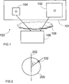
In
Der erste Sensor
Das Kommunikationsnetzwerk
In
Durch das erfindungsgemäße System sind Langzeitbeobachtungen an mechanisch gekoppelten Strukturen möglich durch Vergleich der Messergebnisse mit dem Betrag der Projektion der bekannten und konstanten Erddrehrate auf die empfindliche Sensorachse eines Sensors
Durch die feste Referenz zur Erdrotationsachse
Der zweite Sensor
Eine mechanisch gekoppelte Struktur
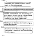
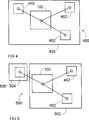
In
Anschließend wird die Orientierung an die Zentraleinheit
In einem Hybridsensorsystem
Mit einem solchen System lassen sich beispielsweise Gebäudebelastungen oder Gebäudeschäden über Deformationen ermitteln, die beispielsweise von Erdbeben verursacht wurden. Eine Deformation der Struktur liefert ein primäres Messsignal, geht einer Schädigung voraus und kann zur quantitativen ad hoc Beurteilung des Schädigungspotentials einer Belastung herangezogen werden. In diesem Konzept werden der erste Sensor
Gemäß
Gemäß
Die Phasengeschwindigkeit c (eine scheinbare Phasengeschwindigkeit in einem heterogenen Medium als Verhältnis der Drehrate Ω und der Beschleunigung a) ändert sich signifikant mit der Bodenbeschaffenheit (beispielsweise weist Granit eine spezifische Phasengeschwindigkeit auf), so dass mithilfe dieses Systems eine Exploration erfolgen kann. Somit kann mit einer tragbaren Vorrichtung nach Lagerstätten gesucht werden bzw. kann durch ein fest installiertes Netz an Sensoren eine Auswertung der Zeitabhängigkeit erfolgen.The phase velocity c (an apparent phase velocity in a heterogeneous medium as the ratio of yaw rate Ω and acceleration a) changes significantly with the soil condition (for example, granite has a specific phase velocity) so that exploration can be performed using this system. Thus it can be searched for deposits with a portable device or can be done by a permanently installed network of sensors an evaluation of the time dependence.
Gemäß der in
Wie bereits geschildert, ist es auch möglich, dass die Zentraleinheit
Ein Zeitbezug kann dabei durch eine Verwendung einer Uhr als Zeitmesseinrichtung
Der Zeitbezug wird beispielsweise dafür benutzt einen zeitlichen Ablauf der Vorgänge zu erhalten und die zu unterschiedlichen Zeitpunkten ermittelten Messergebnisse miteinander in Beziehung zu setzen. So lässt sich die Ausbreitung von Schäden über die Zeit ermitteln und darüber hinaus können weitere Aussagen über die Integrität des Systems getroffen werden. Beispielsweise kann im Fall einer fortschreitenden Ausbreitung einer Verschiebung der Teile einer mechanisch gekoppelten Struktur
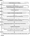
Gemäß
In einem folgenden Schritt S812 werden dann eine Veränderung der Drehrate und gegebenenfalls eine Beschleunigung bestimmt. Durch einen Vergleich mit einem Mastersensor
Claims (13)
Priority Applications (10)
| Application Number | Priority Date | Filing Date | Title |
|---|---|---|---|
| DE102010053582A DE102010053582A1 (en) | 2010-12-06 | 2010-12-06 | System and method for monitoring mechanically coupled structures |
| NZ611045A NZ611045A (en) | 2010-12-06 | 2011-12-05 | System and method for monitoring mechanically coupled structures |
| SG2013040472A SG190409A1 (en) | 2010-12-06 | 2011-12-05 | System and method for monitoring mechanically coupled structures |
| PCT/EP2011/006086 WO2012076145A1 (en) | 2010-12-06 | 2011-12-05 | System and method for monitoring mechanically coupled structures |
| MX2013006114A MX2013006114A (en) | 2010-12-06 | 2011-12-05 | System and method for monitoring mechanically coupled structures. |
| TW100144666A TWI454659B (en) | 2010-12-06 | 2011-12-05 | System and method for monitoring mechanically coupled structures |
| EP11805402.2A EP2649410A1 (en) | 2010-12-06 | 2011-12-05 | System and method for monitoring mechanically coupled structures |
| CN201180057776.1A CN103238040B (en) | 2010-12-06 | 2011-12-05 | For monitoring the system and method for machinery coupled structure |
| JP2013541253A JP5784745B2 (en) | 2010-12-06 | 2011-12-05 | System and method for monitoring mechanically coupled structures |
| US13/990,794 US20130291637A1 (en) | 2010-12-06 | 2011-12-05 | System and Method For Monitoring Mechanically Coupled Structures |
Applications Claiming Priority (1)
| Application Number | Priority Date | Filing Date | Title |
|---|---|---|---|
| DE102010053582A DE102010053582A1 (en) | 2010-12-06 | 2010-12-06 | System and method for monitoring mechanically coupled structures |
Publications (1)
| Publication Number | Publication Date |
|---|---|
| DE102010053582A1 true DE102010053582A1 (en) | 2012-06-06 |
Family
ID=45463517
Family Applications (1)
| Application Number | Title | Priority Date | Filing Date |
|---|---|---|---|
| DE102010053582A Withdrawn DE102010053582A1 (en) | 2010-12-06 | 2010-12-06 | System and method for monitoring mechanically coupled structures |
Country Status (10)
| Country | Link |
|---|---|
| US (1) | US20130291637A1 (en) |
| EP (1) | EP2649410A1 (en) |
| JP (1) | JP5784745B2 (en) |
| CN (1) | CN103238040B (en) |
| DE (1) | DE102010053582A1 (en) |
| MX (1) | MX2013006114A (en) |
| NZ (1) | NZ611045A (en) |
| SG (1) | SG190409A1 (en) |
| TW (1) | TWI454659B (en) |
| WO (1) | WO2012076145A1 (en) |
Cited By (1)
| Publication number | Priority date | Publication date | Assignee | Title |
|---|---|---|---|---|
| DE102013014622A1 (en) * | 2013-09-02 | 2015-03-05 | Northrop Grumman Litef Gmbh | System and method for determining movements and vibrations of moving structures |
Families Citing this family (7)
| Publication number | Priority date | Publication date | Assignee | Title |
|---|---|---|---|---|
| JP6232961B2 (en) * | 2013-11-19 | 2017-11-22 | セイコーエプソン株式会社 | Displacement amount detection device and displacement amount detection method |
| EP3109674B1 (en) * | 2014-02-21 | 2019-03-27 | Furuno Electric Co., Ltd. | Structure displacement detection device, structure displacement sharing system, structure displacement detection method and structure displacement detection program |
| CN104467955A (en) * | 2014-12-24 | 2015-03-25 | 北京奥普科达科技有限公司 | High-sensitivity and high-precision optical fiber identification and calibration method and system |
| CN108700474A (en) * | 2015-11-24 | 2018-10-23 | 电力研究所有限公司 | Device and method for the spin dynamics for directly sensing rotary shaft |
| US11430331B2 (en) * | 2017-09-08 | 2022-08-30 | Uatc, Llc | Power and thermal management systems and methods for autonomous vehicles |
| US10843669B2 (en) | 2017-09-28 | 2020-11-24 | Uatc, Llc | Sensor control system for autonomous vehicle |
| TWI760813B (en) | 2020-08-10 | 2022-04-11 | 國立臺灣科技大學 | Earthquake monitoring system and earthquake monitoring method |
Citations (3)
| Publication number | Priority date | Publication date | Assignee | Title |
|---|---|---|---|---|
| DE69121647T2 (en) * | 1990-06-27 | 1997-04-17 | Chevron Usa Inc | Interface method for determining the voltage formation of a defect area |
| US6005548A (en) * | 1996-08-14 | 1999-12-21 | Latypov; Nurakhmed Nurislamovich | Method for tracking and displaying user's spatial position and orientation, a method for representing virtual reality for a user, and systems of embodiment of such methods |
| DE102006005258A1 (en) * | 2006-02-02 | 2007-08-16 | Litef Gmbh | Method for determining loads / damages of a mechanical structure |
Family Cites Families (15)
| Publication number | Priority date | Publication date | Assignee | Title |
|---|---|---|---|---|
| US6487914B1 (en) * | 1995-09-14 | 2002-12-03 | Structural Integrity Monitoring Systems, Inc. | Structural monitoring sensor system |
| CN2301727Y (en) * | 1997-03-18 | 1998-12-23 | 华中理工大学 | Acceleration sensor based on tunnel effect |
| JP2000249552A (en) * | 1999-02-26 | 2000-09-14 | Japan Aviation Electronics Industry Ltd | Method and device for searching north |
| JP3504529B2 (en) * | 1999-03-31 | 2004-03-08 | 日本航空電子工業株式会社 | Gyro device for monitoring displacement of structures, ground, etc. |
| US6282496B1 (en) * | 1999-10-29 | 2001-08-28 | Visteon Technologies, Llc | Method and apparatus for inertial guidance for an automobile navigation system |
| DE10235163A1 (en) * | 2002-08-01 | 2004-02-19 | Robert Bosch Gmbh | Sensor monitoring method, especially for motor vehicle use, whereby a specific fault pattern is generated according to a fault, sensor or status signal so that when fault pattern is detected a matched response occurs |
| US8140223B2 (en) * | 2003-03-20 | 2012-03-20 | Hemisphere Gps Llc | Multiple-antenna GNSS control system and method |
| US8538734B2 (en) * | 2004-01-21 | 2013-09-17 | California Institute Of Technology | Extreme event performance evaluation using real-time hysteresis monitoring |
| US20060193207A1 (en) * | 2005-02-16 | 2006-08-31 | Honeywell International Inc. | Large area tightly coupled attitude, position, velocity, and acceleration mapping system |
| IL167648A (en) * | 2005-03-24 | 2011-01-31 | Elbit Systems Ltd | Hybrid tracker |
| EP1955830B1 (en) * | 2007-02-06 | 2014-04-09 | Abb Research Ltd. | A method and a control system for monitoring the condition of an industrial robot |
| US8005635B2 (en) * | 2007-08-14 | 2011-08-23 | Ching-Fang Lin | Self-calibrated azimuth and attitude accuracy enhancing method and system (SAAAEMS) |
| JP5292864B2 (en) * | 2008-03-12 | 2013-09-18 | シンフォニアテクノロジー株式会社 | Displacement measuring device for dam body |
| EP2265918A1 (en) * | 2008-04-01 | 2010-12-29 | Structural Data, S.L. | System and procedure for the real-time monitoring of fixed or mobile rigid structures such as building structures, aircraft, ships and/or the like |
| IL198109A (en) * | 2009-04-07 | 2013-01-31 | Azimuth Technologies Ltd | North finding device, system and method |
-
2010
- 2010-12-06 DE DE102010053582A patent/DE102010053582A1/en not_active Withdrawn
-
2011
- 2011-12-05 SG SG2013040472A patent/SG190409A1/en unknown
- 2011-12-05 NZ NZ611045A patent/NZ611045A/en not_active IP Right Cessation
- 2011-12-05 TW TW100144666A patent/TWI454659B/en not_active IP Right Cessation
- 2011-12-05 MX MX2013006114A patent/MX2013006114A/en active IP Right Grant
- 2011-12-05 CN CN201180057776.1A patent/CN103238040B/en not_active Expired - Fee Related
- 2011-12-05 US US13/990,794 patent/US20130291637A1/en not_active Abandoned
- 2011-12-05 JP JP2013541253A patent/JP5784745B2/en not_active Expired - Fee Related
- 2011-12-05 WO PCT/EP2011/006086 patent/WO2012076145A1/en active Application Filing
- 2011-12-05 EP EP11805402.2A patent/EP2649410A1/en not_active Withdrawn
Patent Citations (3)
| Publication number | Priority date | Publication date | Assignee | Title |
|---|---|---|---|---|
| DE69121647T2 (en) * | 1990-06-27 | 1997-04-17 | Chevron Usa Inc | Interface method for determining the voltage formation of a defect area |
| US6005548A (en) * | 1996-08-14 | 1999-12-21 | Latypov; Nurakhmed Nurislamovich | Method for tracking and displaying user's spatial position and orientation, a method for representing virtual reality for a user, and systems of embodiment of such methods |
| DE102006005258A1 (en) * | 2006-02-02 | 2007-08-16 | Litef Gmbh | Method for determining loads / damages of a mechanical structure |
Cited By (1)
| Publication number | Priority date | Publication date | Assignee | Title |
|---|---|---|---|---|
| DE102013014622A1 (en) * | 2013-09-02 | 2015-03-05 | Northrop Grumman Litef Gmbh | System and method for determining movements and vibrations of moving structures |
Also Published As
| Publication number | Publication date |
|---|---|
| CN103238040B (en) | 2016-06-01 |
| CN103238040A (en) | 2013-08-07 |
| TWI454659B (en) | 2014-10-01 |
| MX2013006114A (en) | 2013-10-01 |
| US20130291637A1 (en) | 2013-11-07 |
| JP2014501917A (en) | 2014-01-23 |
| SG190409A1 (en) | 2013-07-31 |
| TW201235637A (en) | 2012-09-01 |
| NZ611045A (en) | 2015-05-29 |
| EP2649410A1 (en) | 2013-10-16 |
| JP5784745B2 (en) | 2015-09-24 |
| WO2012076145A1 (en) | 2012-06-14 |
Similar Documents
| Publication | Publication Date | Title |
|---|---|---|
| DE102010053582A1 (en) | System and method for monitoring mechanically coupled structures | |
| DE102009061036B4 (en) | Residue generation apparatus and method for detecting erroneous transients, drifts or oscillations in the system behavior of a system of an aircraft, and aircraft | |
| DE102009000743B4 (en) | Vibration compensation for rotation rate sensors | |
| DE102005052892A1 (en) | Accelerometer based tilt sensor and method of use | |
| DE102008003609A1 (en) | Pedalwegprüfsystem | |
| WO2007088042A1 (en) | Method for determining loads on/damage to a mechanical structure | |
| DE102012104358A1 (en) | Method and system for quadrature error compensation | |
| EP3052359A1 (en) | Method and device for monitoring the function of a driver assistance system | |
| DE102021004103A1 (en) | Method and arrangement for monitoring and detecting sensor errors in inertial measuring systems | |
| DE102009029216A1 (en) | Method for self-adjustment of a three-axis acceleration sensor in operation and sensor arrangement with a three-dimensional acceleration sensor | |
| DE112021006803T5 (en) | Method for calculating speed and acceleration based on a regularization algorithm and a measuring device | |
| DE2827669C2 (en) | Method for determining the magnitude and phase position of vibrations detected by transducers, especially in balancing technology | |
| DE102017108289A1 (en) | Machine tool control device with malfunction diagnostic function of the sensor for detecting a 1-turn signal | |
| WO2014184225A1 (en) | Rotation rate sensor for detecting a rotation rate, having a substrate which has a main extension plane | |
| DE102015117942B4 (en) | Gyroscope angular velocity calculation for an interferometric fiber optic gyroscope | |
| WO2011110382A1 (en) | Method and device for detecting a deviation of a rotation rate signal of a rotation rate sensor | |
| DE102011106924A1 (en) | An encoder having a function of detecting an amount of spurious signals | |
| EP3367059B1 (en) | Optoelectronic measuring device with magnetic compass and compensation functionality | |
| DE102010000929A1 (en) | Method for providing signal indicating spatial alignment of portable device e.g. mobile phone, involves detecting parameter influencing direction determination by using sensor, and determining reference direction based on detected parameter | |
| DE102021127489B3 (en) | Sensor for detecting periodic movements | |
| WO2005124369A1 (en) | Acceleration sensor and method for detecting acceleration | |
| EP3227717A1 (en) | Method and device for determining statistical properties of raw measured values | |
| DE102010016640B4 (en) | System and method for the quasi-distributed measurement of a measured variable | |
| DE102009021557B4 (en) | Method for determining at least one movement quantity of a rotating shaft, wave examination and / or monitoring device for its implementation and use thereof | |
| WO2015120827A1 (en) | Method and device for measuring dielectric parameters of the isolation of high voltage appliances |
Legal Events
| Date | Code | Title | Description |
|---|---|---|---|
| R119 | Application deemed withdrawn, or ip right lapsed, due to non-payment of renewal fee |