DE102010050765B9 - Position measuring system for detecting an excellent position of a linearly movable guide element - Google Patents
Position measuring system for detecting an excellent position of a linearly movable guide element Download PDFInfo
- Publication number
- DE102010050765B9 DE102010050765B9 DE102010050765A DE102010050765A DE102010050765B9 DE 102010050765 B9 DE102010050765 B9 DE 102010050765B9 DE 102010050765 A DE102010050765 A DE 102010050765A DE 102010050765 A DE102010050765 A DE 102010050765A DE 102010050765 B9 DE102010050765 B9 DE 102010050765B9
- Authority
- DE
- Germany
- Prior art keywords
- measuring system
- reed contact
- position measuring
- circuit arrangement
- contact element
- Prior art date
- Legal status (The legal status is an assumption and is not a legal conclusion. Google has not performed a legal analysis and makes no representation as to the accuracy of the status listed.)
- Expired - Fee Related
Links
Images
Classifications
-
- G—PHYSICS
- G01—MEASURING; TESTING
- G01B—MEASURING LENGTH, THICKNESS OR SIMILAR LINEAR DIMENSIONS; MEASURING ANGLES; MEASURING AREAS; MEASURING IRREGULARITIES OF SURFACES OR CONTOURS
- G01B7/00—Measuring arrangements characterised by the use of electric or magnetic techniques
- G01B7/14—Measuring arrangements characterised by the use of electric or magnetic techniques for measuring distance or clearance between spaced objects or spaced apertures
-
- G—PHYSICS
- G01—MEASURING; TESTING
- G01D—MEASURING NOT SPECIALLY ADAPTED FOR A SPECIFIC VARIABLE; ARRANGEMENTS FOR MEASURING TWO OR MORE VARIABLES NOT COVERED IN A SINGLE OTHER SUBCLASS; TARIFF METERING APPARATUS; MEASURING OR TESTING NOT OTHERWISE PROVIDED FOR
- G01D5/00—Mechanical means for transferring the output of a sensing member; Means for converting the output of a sensing member to another variable where the form or nature of the sensing member does not constrain the means for converting; Transducers not specially adapted for a specific variable
- G01D5/12—Mechanical means for transferring the output of a sensing member; Means for converting the output of a sensing member to another variable where the form or nature of the sensing member does not constrain the means for converting; Transducers not specially adapted for a specific variable using electric or magnetic means
- G01D5/14—Mechanical means for transferring the output of a sensing member; Means for converting the output of a sensing member to another variable where the form or nature of the sensing member does not constrain the means for converting; Transducers not specially adapted for a specific variable using electric or magnetic means influencing the magnitude of a current or voltage
- G01D5/20—Mechanical means for transferring the output of a sensing member; Means for converting the output of a sensing member to another variable where the form or nature of the sensing member does not constrain the means for converting; Transducers not specially adapted for a specific variable using electric or magnetic means influencing the magnitude of a current or voltage by varying inductance, e.g. by a movable armature
- G01D5/2006—Mechanical means for transferring the output of a sensing member; Means for converting the output of a sensing member to another variable where the form or nature of the sensing member does not constrain the means for converting; Transducers not specially adapted for a specific variable using electric or magnetic means influencing the magnitude of a current or voltage by varying inductance, e.g. by a movable armature by influencing the self-induction of one or more coils
- G01D5/2033—Mechanical means for transferring the output of a sensing member; Means for converting the output of a sensing member to another variable where the form or nature of the sensing member does not constrain the means for converting; Transducers not specially adapted for a specific variable using electric or magnetic means influencing the magnitude of a current or voltage by varying inductance, e.g. by a movable armature by influencing the self-induction of one or more coils controlling the saturation of a magnetic circuit by means of a movable element, e.g. a magnet
-
- G—PHYSICS
- G01—MEASURING; TESTING
- G01F—MEASURING VOLUME, VOLUME FLOW, MASS FLOW OR LIQUID LEVEL; METERING BY VOLUME
- G01F23/00—Indicating or measuring liquid level or level of fluent solid material, e.g. indicating in terms of volume or indicating by means of an alarm
- G01F23/30—Indicating or measuring liquid level or level of fluent solid material, e.g. indicating in terms of volume or indicating by means of an alarm by floats
- G01F23/64—Indicating or measuring liquid level or level of fluent solid material, e.g. indicating in terms of volume or indicating by means of an alarm by floats of the free float type without mechanical transmission elements
- G01F23/72—Indicating or measuring liquid level or level of fluent solid material, e.g. indicating in terms of volume or indicating by means of an alarm by floats of the free float type without mechanical transmission elements using magnetically actuated indicating means
- G01F23/74—Indicating or measuring liquid level or level of fluent solid material, e.g. indicating in terms of volume or indicating by means of an alarm by floats of the free float type without mechanical transmission elements using magnetically actuated indicating means for sensing changes in level only at discrete points
-
- G—PHYSICS
- G01—MEASURING; TESTING
- G01D—MEASURING NOT SPECIALLY ADAPTED FOR A SPECIFIC VARIABLE; ARRANGEMENTS FOR MEASURING TWO OR MORE VARIABLES NOT COVERED IN A SINGLE OTHER SUBCLASS; TARIFF METERING APPARATUS; MEASURING OR TESTING NOT OTHERWISE PROVIDED FOR
- G01D5/00—Mechanical means for transferring the output of a sensing member; Means for converting the output of a sensing member to another variable where the form or nature of the sensing member does not constrain the means for converting; Transducers not specially adapted for a specific variable
- G01D5/12—Mechanical means for transferring the output of a sensing member; Means for converting the output of a sensing member to another variable where the form or nature of the sensing member does not constrain the means for converting; Transducers not specially adapted for a specific variable using electric or magnetic means
- G01D5/14—Mechanical means for transferring the output of a sensing member; Means for converting the output of a sensing member to another variable where the form or nature of the sensing member does not constrain the means for converting; Transducers not specially adapted for a specific variable using electric or magnetic means influencing the magnitude of a current or voltage
- G01D5/20—Mechanical means for transferring the output of a sensing member; Means for converting the output of a sensing member to another variable where the form or nature of the sensing member does not constrain the means for converting; Transducers not specially adapted for a specific variable using electric or magnetic means influencing the magnitude of a current or voltage by varying inductance, e.g. by a movable armature
-
- G—PHYSICS
- G21—NUCLEAR PHYSICS; NUCLEAR ENGINEERING
- G21C—NUCLEAR REACTORS
- G21C17/00—Monitoring; Testing ; Maintaining
- G21C17/10—Structural combination of fuel element, control rod, reactor core, or moderator structure with sensitive instruments, e.g. for measuring radioactivity, strain
-
- G—PHYSICS
- G21—NUCLEAR PHYSICS; NUCLEAR ENGINEERING
- G21C—NUCLEAR REACTORS
- G21C7/00—Control of nuclear reaction
- G21C7/06—Control of nuclear reaction by application of neutron-absorbing material, i.e. material with absorption cross-section very much in excess of reflection cross-section
- G21C7/08—Control of nuclear reaction by application of neutron-absorbing material, i.e. material with absorption cross-section very much in excess of reflection cross-section by displacement of solid control elements, e.g. control rods
- G21C7/10—Construction of control elements
-
- Y—GENERAL TAGGING OF NEW TECHNOLOGICAL DEVELOPMENTS; GENERAL TAGGING OF CROSS-SECTIONAL TECHNOLOGIES SPANNING OVER SEVERAL SECTIONS OF THE IPC; TECHNICAL SUBJECTS COVERED BY FORMER USPC CROSS-REFERENCE ART COLLECTIONS [XRACs] AND DIGESTS
- Y02—TECHNOLOGIES OR APPLICATIONS FOR MITIGATION OR ADAPTATION AGAINST CLIMATE CHANGE
- Y02E—REDUCTION OF GREENHOUSE GAS [GHG] EMISSIONS, RELATED TO ENERGY GENERATION, TRANSMISSION OR DISTRIBUTION
- Y02E30/00—Energy generation of nuclear origin
- Y02E30/30—Nuclear fission reactors
Abstract
Stellungsmesssystem (1) zur Erfassung einer ausgezeichneten Position (xmin, xmax) eines bezüglich eines Führsystems (2) entlang eines geradlinigen Weges (x) ausgedehnten und entlang des geradlinigen Weges (x) bewegbaren Führstabes (3), mit einer Anzahl von Reed-Kontaktelementen (5) und mit mindestens einem Magnetelement (7), wobei • das Magnetelement (7) zur Bildung eines magnetischen Feldes (H) eingerichtet ist, • das Magnetelement (7) mit dem Führstab (3) verbunden ist, • das oder jedes Reed-Kontaktelement (5) jeweils innerhalb eines Detektionsbereiches zur Detektion eines magnetischen Feldes (H), dessen Feldstärke am Ort des Reed-Kontaktelements (5) größer ist als ein vordefinierter Schwellwert, ausgebildet ist, und • mindestens ein Reed-Kontaktelement (5) mit dem Führsystem (2) verbunden und in einer Umgebung (Ux) des Weges (x) angeordnet ist, und eine Schaltungsanordnung (12) ausgestaltet ist, die mindestens eine ohmsche Widerstandseinheit (R1, R2) umfasst, • die mit mindestens einer Induktionsspule (9) eine Reihenschaltung (12) ausbildet, und • die mit mindestens einem Reed-Kontaktelement (5) eine Schaltungsschleife (14, 15) ausbildet.Attitude measuring system (1) for detecting an excellent position (xmin, xmax) of a guide bar (3) extended relative to a guide system (2) along a rectilinear path (x) and movable along the rectilinear path (x), comprising a number of reed contact elements (5) and with at least one magnetic element (7), wherein • the magnetic element (7) is arranged to form a magnetic field (H), • the magnetic element (7) is connected to the guide rod (3), • the or each reed Contact element (5) each within a detection range for detecting a magnetic field (H) whose field strength at the location of the reed contact element (5) is greater than a predefined threshold, is formed, and • at least one reed contact element (5) the guide system (2) and in an environment (Ux) of the path (x) is arranged, and a circuit arrangement (12) is configured which comprises at least one ohmic resistance unit (R1, R2), the with at least one induction coil (9) forms a series circuit (12), and • with at least one reed contact element (5) forms a circuit loop (14, 15).
Description
Die Erfindung betrifft ein Stellungsmesssystem zur Erfassung einer ausgezeichneten Position, insbesondere einer maximalen und minimalen Position, eines linear beweglichen Führungselementes.The invention relates to a position measuring system for detecting an excellent position, in particular a maximum and minimum position, of a linearly movable guide element.
Stellungsmesssysteme sind aus den Druckschriften
In einer kerntechnischen Anlage, beispielsweise in einer Kernkraftwerksanlage, werden linear verfahrbare Steuerstäbe verwendet, um Kettenreaktionen von Kernzerfallsprozessen in einem Reaktor, bei denen Teilchenstrahlung – insbesondere Neutronenstrahlung – emittiert wird, durch Absorption der Strahlung zu kontrollieren. Je weiter solche Steuerstäbe, die typischerweise in Gruppen gebündelt angeordnet sind, zwischen die nuklearen Brennelemente geschoben werden, desto größere Anteile der die Kettenreaktion weiter antreibenden Teilchenstrahlung werden absorbiert, so dass die Kettenreaktion entsprechend langsamer abläuft und bei voller Ausfahrposition der Steuerstäbe idealerweise zum Erliegen gebracht werden kann. Zustand und Ablauf der Kettenreaktion sind somit von den Ausfahrpositionen der linear verfahrbaren Steuerstäbe abhängig und sind durch diese bestimmt. Eine genaue Kenntnis der Positionen der Steuerstäbe – insbesondere der jeweils maximal ausgefahrenen Positionen – ist somit für eine Regelung des Betriebszustandes und somit insbesondere für die Sicherheit relevant.In a nuclear plant, for example in a nuclear power plant, linearly movable control rods are used to control chain reactions of nuclear decay processes in a reactor in which particle radiation - in particular neutron radiation - is emitted by absorption of the radiation. The farther such control rods, which are typically clustered, are pushed between the nuclear fuel assemblies, the greater the amount of particle radiation driving the chain reaction will be absorbed, so that the chain reaction will be correspondingly slower and ideally halted at the full extension position of the control rods can. The state and sequence of the chain reaction are thus dependent on the extension positions of the linearly displaceable control rods and are determined by them. A precise knowledge of the positions of the control rods - in particular of the respective maximum extended positions - is thus relevant for a control of the operating state and thus in particular for safety.
Stellungsmesssysteme für Steuerstäbe umfassen in der Regel Vorrichtungen zur Anwendung elektromagnetisch induktiver Messverfahren, bei denen jeweils ausgenutzt wird, dass die zeitliche Veränderung eines Magnetfeldes in einem elektrischen Leiter eine elektrische Spannung induziert. Eine derartige Vorrichtung umfasst üblicherweise eine oder mehrere Primärspulen zur Bereitstellung eines solchen Magnetfeldes. Durch einen Steuerstab im Bereich des Magnetfeldes wird das Magnetfeld verändert, was dazu führt, dass die in entlang des linearen Verfahrweges angeordneten Induktionsspulen induzierte Spannung verändert wird. Aus der Größe der Induktionsspannung kann die Position des Steuerstabes bestimmt werden. Zur Erfassung der unteren und/oder der oberen Endstellung des Steuerstabes sind zumeist separate Spulengruppen eingerichtet, deren Messsignale über jeweils separate Leitungen zur Auswerteeinheit übertragen werden. Ein Spannungssignal von diesen Spulen gibt Aufschluss darüber, ob der Steuerstab die untere bzw. die obere Endstellung erreicht hat.Position measuring systems for control rods generally include devices for the application of electromagnetic inductive measuring methods, in which it is utilized in each case that the temporal change of a magnetic field in an electrical conductor induces an electrical voltage. Such a device usually comprises one or more primary coils for providing such a magnetic field. By a control rod in the region of the magnetic field, the magnetic field is changed, which results in that the voltage induced in along the linear travel induced inductance coil is changed. From the size of the induction voltage, the position of the control rod can be determined. For detecting the lower and / or the upper end position of the control rod, separate coil groups are usually set up, the measurement signals of which are transmitted via separate lines to the evaluation unit. A voltage signal from these coils provides information about whether the control rod has reached the lower or the upper end position.
Ein Nachteil des oben dargestellten Stellungsmesssystems ist darin begründet, dass zur Erfassung der Positionen des Steuerstabes eine Mehrzahl von Sekundärspulen erforderlich ist, deren Signalleitungen aus dem inneren Reaktorbereich – dem so genannten Containment – herausgeführt werden müssen. Insbesondere die Spulen zur Erfassung der Endstellungen des Steuerstabes erfordern zusätzliche Messleitungen. Darüber hinaus ist nachteilig, dass abhängig von der tatsächlichen Position des Steuerstabes das Spannungssignal von der Induktionsspule im Umgebungsbereich der minimalen oder maximalen endseitigen Ausfahrposition des Steuerstabes kontinuierlich variiert. Damit lässt sich anhand der Größe des Spannungssignals zwar grob auf die minimale oder maximale Ausfahrposition des Steuerstabes schließen; das Signal ist aber in abgeschwächter Form immer noch vorhanden, wenn sich der Steuerstab nicht mehr in seiner minimalen oder maximalen Ausfahrposition befindet, beispielsweise dann, wenn der Steuerstab eine gewisse Wegstrecke aus dem Reaktor gezogen ist. Das induktive Messverfahren ist daher für eine präzise und eindeutige Endstellungsdetektion häufig zu ungenau.A disadvantage of the position measuring system shown above is that for detecting the positions of the control rod, a plurality of secondary coils is required whose signal lines from the inner reactor area - the so-called containment - must be led out. In particular, the coils for detecting the end positions of the control rod require additional measuring lines. Moreover, it is disadvantageous that, depending on the actual position of the control rod, the voltage signal from the induction coil in the surrounding area of the minimum or maximum end-side extension position of the control rod varies continuously. Although the size of the voltage signal makes it possible to roughly conclude the minimum or maximum extension position of the control rod; However, the signal is still present in a weakened form when the control rod is no longer in its minimum or maximum extended position, for example, when the control rod is pulled a certain distance from the reactor. The inductive measuring method is therefore often too imprecise for precise and unambiguous end position detection.
Aufgabe der Erfindung ist es, ein Stellungsmesssystem zur Erfassung einer ausgezeichneten Position, insbesondere einer Extremalposition, eines entlang eines geradlinigen Weges bewegbaren Steuerstabes anzugeben, für welches eine möglichst geringe Anzahl von Messleitungen erforderlich ist und welches möglichst genau und zuverlässig ist. Das Stellungsmesssystem sollte sich insbesondere auf einfache Weise in bestehende induktive Stellungsmesssysteme integrieren lassen.The object of the invention is to provide a position measuring system for detecting an excellent position, in particular an extreme position, of a control rod movable along a rectilinear path, for which the smallest possible number of test leads is required and which is as accurate and reliable as possible. In particular, the position measuring system should be easy to integrate into existing inductive position measuring systems.
Die Aufgabe wird erfindungsgemäß durch die Merkmale des Anspruchs 1 gelöst.The object is achieved by the features of
Danach ist ein Stellungsmesssystem zur Erfassung einer ausgezeichneten Position, insbesondere einer Extremalposition eines bezüglich eines Führsystems entlang eines geradlinigen Weges ausgedehnten und entlang des geradlinigen Weges bewegbaren Führstabes vorgesehen, mit einer Anzahl von Reed-Kontaktelementen und mit mindestens einem Magnetelement, wobei das Magnetelement zur Bildung eines magnetischen Feldes eingerichtet ist, das Magnetelement mit dem Führstab verbunden ist, das oder jedes Reed-Kontaktelement jeweils innerhalb eines Detektionsbereiches zur Detektion eines magnetischen Feldes, dessen Feldstärke am Ort des Reed-Kontaktelements größer ist als ein vordefinierter Schwellwert, ausgebildet ist, und mindestens ein Reed-Kontaktelement mit dem Führsystem verbunden und in einer Umgebung des Weges angeordnet ist. Zudem ist eine Schaltungsanordnung (
- • die mit mindestens einer Induktionsspule (
9 ) eine Reihenschaltung (12 ) ausbildet, und - • die mit mindestens einem Reed-Kontaktelement (
5 ) eine Schaltungsschleife (14 ,15 ) ausbildet.
- • with at least one induction coil (
9 ) a series connection (12 ), and - • with at least one reed contact element (
5 ) a circuit loop (14 .15 ) trains.
Die Erfindung geht von der Überlegung aus, mit Hilfe eines Magnetelementes ein Magnetfeld mit dem Führstab ortsmäßig zu koppeln und mittels einer Detektion des Magnetfeldes durch ein externes, mit dem Führsystem ortsfest verbundenes Reed-Kontaktelement, die entsprechende Position des Führstabes bezüglich des Führsystems zu erfassen. Insbesondere können auf diese Weise diskrete Positionswerte des Führstabes erfasst werden, beispielsweise eine Extremalposition. Ein Reed-Kontaktelement umfasst dabei zwei Kontaktzungen, deren Kern jeweils in der Regel aus einem ferromagnetischen Metall gebildet ist. Ein Magnetfeld im Bereich des Reed-Kontaktelementes – hervorgerufen durch den Permanentmagneten am Steuerstab – führt zu einer Anziehung der beiden Kontaktzungen. Überschreitet die Feldstärke des Magnetfeldes einen Schwellwert, so ist zwischen den beiden Kontaktzungen ein Kontaktschluss ausgebildet, so dass ein elektrischer Steuerstrom über den Kontakt fließen kann. Zur Verbesserung der Leitfähigkeit und zur Verminderung eines vorzeitigen Kontaktschlusses sind die Kontaktzungen üblicherweise mit einem Edelmetall beschichtet, beispielsweise Kupfer oder Silber, bzw. sind in einen evakuierten oder mit Schutzgas befüllten Glaskolben eingeschlossen. Reed-Kontaktelemente sind über einen weiten Größenbereich skalierbar und sind robust und kostengünstig verfügbar. The invention is based on the idea of using a magnetic element to couple a magnetic field with the guide rod and by means of a detection of the magnetic field by an external, with the guide system fixedly connected reed contact element to detect the corresponding position of the guide rod with respect to the guide system. In particular, discrete position values of the guide rod can be detected in this way, for example an extreme position. A reed contact element comprises two contact tongues, the core of which is usually formed in each case from a ferromagnetic metal. A magnetic field in the region of the reed contact element - caused by the permanent magnet on the control rod - leads to an attraction of the two contact tongues. If the field strength of the magnetic field exceeds a threshold value, then a contact closure is formed between the two contact tongues so that an electrical control current can flow via the contact. To improve the conductivity and to reduce a premature contact closure, the contact tongues are usually coated with a noble metal, for example copper or silver, or are enclosed in an evacuated or filled with inert gas flask. Reed contact elements are scalable over a wide range of sizes and are robust and cost-effective.
Als Position des Führstabes ist die Lage eines bezüglich des Führstabes stationären Referenzpunktes definiert, wobei der Referenzpunkt bezüglich des geradlinigen Weges genau eine Ortskoordinate hat. Vorzugsweise ist der Referenzpunkt an dem Ort des Führstabes gewählt, an dem ein beliebiges, aber fest gewähltes Magnetelement angeordnet ist. Bei nur einem Magnetelement ist diese Wahl eindeutig. Die zuletzt genannte spezielle Wahl des Referenzpunktes stellt keine Beschränkung der Allgemeinheit dar. Bei einer anderen Wahl des Referenzpunktes sind die gemessenen Positionswerte im Vergleich zu den Werten bei der speziellen Wahl des Referenzpunktes um eine konstante Länge verschoben, die durch den Abstand zwischen dem Magnetelement und dem Referenzpunkt gegeben ist.As the position of the guide rod, the position of a reference point stationary relative to the guide rod is defined, wherein the reference point has exactly one location coordinate with respect to the rectilinear path. Preferably, the reference point is selected at the location of the guide rod on which an arbitrary, but firmly selected magnetic element is arranged. With only one magnetic element, this choice is unique. The latter special choice of the reference point does not constitute a restriction of the generality. In another choice of the reference point, the measured position values are shifted by a constant length compared to the values for the specific choice of the reference point, which is defined by the distance between the magnetic element and the Reference point is given.
Darüber hinaus umfasst die Schaltungsanordnung mindestens eine ohmsche Widerstandseinheit, die mit mindestens einer Induktionsspule eine Reihenschaltung ausbildet, und die mit mindestens einem Kontaktsensor eine Schaltungsschleife ausbildet. Da auch die Induktionsspule einen ohmschen Widerstand aufweist, ist der Gesamtwiderstand in einer Reihenschaltung aus der ohmschen Widerstandseinheit und der Induktionsspule als die Summe beider Widerstände gegeben. Da der Kontaktsensor mit der ohmschen Widerstandseinheit eine Schaltungsschleife bildet, ist die ohmsche Widerstandseinheit bei geschlossenem Kontaktsensor überbrückt und somit kurzgeschlossen, so dass in diesem Fall in den messbaren Gesamtwiderstand nur der ohmsche Widerstand der Induktionsspule eingeht. Die Topologie der Schaltungsanordnung bildet somit eine Detektion des Kontaktsensors auf eine unstetige Widerstandsänderung ab, so dass beispielsweise das Erreichen einer Extremalposition des Führstabes anhand einer solchen sprunghaften Veränderung des Widerstandswertes erkennbar ist, eine solche kann mit einfachen Mitteln gemessen werden.In addition, the circuit arrangement comprises at least one ohmic resistance unit, which forms a series circuit with at least one induction coil and which forms a circuit loop with at least one contact sensor. Since the induction coil has an ohmic resistance, the total resistance in a series circuit of the ohmic resistance unit and the induction coil is given as the sum of both resistances. Since the contact sensor forms a circuit loop with the ohmic resistance unit, the ohmic resistance unit is bridged when the contact sensor is closed and thus short-circuited, so that in this case only the ohmic resistance of the induction coil is included in the measurable total resistance. The topology of the circuit arrangement thus forms a detection of the contact sensor on a discontinuous change in resistance, so that, for example, the achievement of an extreme position of the guide rod is recognizable by such a sudden change in the resistance value, such can be measured by simple means.
Weiterhin ist die Positionserfassung eindeutig, da das Reed-Kontaktelement dann und nur dann erfassend reagiert, wenn ein Magnetfeld im Detektionsbereich ist, dessen Feldstärke am Ort des Reed-Kontaktelements größer ist als der Schwellwert. Bei einer Positionsveränderung des Führstabes, die größer ist als die räumliche Trennungsschärfe des Reed-Kontaktelements, findet somit keine kontinuierliche Signalgebung des Reed-Kontaktelements statt. Vielmehr ist eine verlässliche binäre Auskunft der Art „Endposition erreicht: ja/nein?” ermöglicht.Furthermore, the position detection is unambiguous, since the reed contact element then and only then detects responsive when a magnetic field in the detection area, the field strength at the location of the reed contact element is greater than the threshold value. In a position change of the guide rod, which is greater than the spatial separation sharpness of the reed contact element, thus no continuous signaling of the reed contact element takes place. Rather, a reliable binary information of the kind "end position reached: yes / no?" Allows.
Sind mehrere Reed-Kontaktelemente an ein und demselben Ort des Führsystems installiert, dann ist der Redundanzgrad einer Positionserfassung entsprechend erhöht. Ein erfindungsgemäßes Stellungsmesssystem ist daher prinzipiell mit einem hohen Redundanzgrad ausführbar und ist dementsprechend zuverlässig. Dabei muss man systembedingt allerdings den Nachteil einer größeren Zahl von Leitungen in Kauf nehmen.If several reed contact elements are installed at one and the same location of the guidance system, the degree of redundancy of a position detection is correspondingly increased. An inventive position measuring system is therefore in principle executable with a high degree of redundancy and is therefore reliable. However, due to the system, you have to accept the disadvantage of a larger number of lines.
Darüber hinaus kann das erfindungsgemäße Stellungsmesssystem mit bekannten Systemen zur Stellungsmessung, insbesondere mit Systemen zur Anwendung induktiver Messverfahren, kombiniert werden, wobei insbesondere auf bereits bestehende Signalleitungen zurückgegriffen werden kann (Mehrfachnutzung).In addition, the position measuring system according to the invention can be combined with known systems for position measurement, in particular with systems for the application of inductive measuring methods, it being possible in particular to make use of existing signal lines (multiple use).
Vorzugsweise ist das Magnetelement als ein Permanentmagnet ausgebildet. Für einen Permanentmagneten sind – anders als bei einer einen Elektromagneten bildenden Spule – keine elektrischen Leiter nötig, die als zusätzliche Leitungen an oder in dem Führstab und aus dem Containment herausgeführt werden müssen. Die Anzahl an möglichen zusätzlichen Leitungen, die für das Stellungsmesssystem aus dem Containment herauszuführen sind, bleibt somit auf die Sensorelemente beschränkt.Preferably, the magnetic element is designed as a permanent magnet. For a permanent magnet - unlike a coil forming an electromagnet - no electrical conductors are necessary, which must be led out as additional lines on or in the guide rod and from the containment. The number of possible additional lines that are to be led out of the containment for the position measuring system, thus remains limited to the sensor elements.
Zweckmäßigerweise ist das Magnetelement mit dem Führstab endseitig verbunden. In einer derartigen Position ist das Magnetelement besonders einfach mit dem Führstab zu verbinden und kann – beispielsweise als Permanentmagnet – in Form einer Magnetplatte oder einer Magnetkreisscheibe auf den Führstab endseitig aufgefügt sein. Darüber hinaus kann damit für ein Reed-Kontaktelement am Ort einer möglichen extremalen Auslenkung der entsprechenden Endseite des Führstabes bezüglich des Führsystems die Extremalposition des Führstabes erfasst werden.Conveniently, the magnetic element is connected to the end of the guide rod. In such a position, the magnetic element is particularly easy to connect to the guide rod and can - for example, as a permanent magnet - in the form of a magnetic disk or a magnetic disk on the guide rod be fitted end. In addition, it can thus for a reed contact element at the site of a possible extreme deflection of the corresponding extreme end of the guide rod with respect to the guide system the extremal position of the guide rod are detected.
Daher erfasst zweckdienlicherweise der Detektionsbereich mindestens eines Reed-Kontaktelements den in der Extremalposition angeordneten Führstab endseitig.Therefore, the detection area of at least one reed contact element expediently detects the guide bar arranged in the extreme position at the end.
In einer geeigneten Ausführung des Stellungsmesssystems ist der Führstab zwischen einer minimalen Ausfahrposition und einer maximalen Ausfahrposition entlang des geradlinigen Weges bewegbar. Mittels geeignet lokalisierten Sensorelementen können somit die beiden extremalen Ausfahrpositionen des Führstabes erfasst werden.In a suitable embodiment of the position measuring system, the guide bar is movable between a minimum extension position and a maximum extension position along the rectilinear path. By means of suitably localized sensor elements, the two extreme extension positions of the guide rod can thus be detected.
In einer bevorzugten Ausführungsvariante des Stellungsmesssystems ist mindestens ein Reed-Kontaktelement mit einer elektrischen Schaltungsanordnung verbunden, welche Schaltungsanordnung mit einer Auswerte- und/oder Steuereinheit verbunden ist, sowie eine Anzahl von elektrischen Induktionsspulen umfasst. Die elektrische(n) Induktionsspule(n) ist bzw. sind zur Anwendung eines induktiven Messvorgangs ausgebildet. Durch die schaltungstechnische Verbindung kann die oder jede Induktionsspule mit dem Reed-Kontaktelement über ein und dieselbe Steuereinheit angesteuert und kontrolliert werden. Auf diese Weise kann ein hoher Grad an Redundanz und/oder eine hohe örtliche Auflösung der Positionsermittlung erreicht werden, ohne dass zusätzliche elektrische Leitungen aus dem Containment herausgeführt werden müssen.In a preferred embodiment of the position measuring system, at least one reed contact element is connected to an electrical circuit arrangement, which circuit arrangement is connected to an evaluation and / or control unit, and comprises a number of electrical induction coils. The electrical induction coil (s) is / are designed for the application of an inductive measuring process. Through the circuitry connection, the or each induction coil can be controlled and controlled with the reed contact element via one and the same control unit. In this way, a high degree of redundancy and / or a high spatial resolution of the position detection can be achieved without additional electrical lines must be led out of the containment.
In einer besonders geeigneten Weiterbildung des Stellungsmesssystems umfasst die Schaltungsanordnung zwei ohmsche Widerstandseinheiten, die mit einer Induktionsspule eine Reihenschaltung ausbilden, wobei jeweils einer der beiden ohmschen Widerstände mit jeweils einer Endseite (Anschlussende) der Induktionsspule verbunden ist, und umfasst eine Mehrzahl von Kontaktsensoren, wobei jeder Kontaktsensor mit einem der ohmschen Widerstände eine Schaltungsschleife ausbildet. Insbesondere sind zwei Kontaktsensoren gegeben, und jeder Kontaktsensor bildet mit genau einer ohmschen Widerstandseinheit eine Schaltungsschleife aus. Eine solche Schaltungstopologie stellt einen Spezialfall der im letzten Abschnitt dargelegten Schaltungstopologie dar, die zur Identifikation zweier unterschiedlicher Sensorsignale geeignet sind, beispielsweise zum Zweck der Detektion einer Minimal- und einer Maximalposition des Führstabes. Insbesondere weisen die beiden ohmschen Widerstandseinheiten unterschiedliche ohmsche Widerstandswerte auf, so dass an der Größe der Veränderung des Gesamtwiderstandswertes erkennbar ist, welcher der beiden Kontaktsensoren einen elektrischen Kontaktschuss bildet. Sind mehr als zwei Kontaktsensoren gegeben, so existieren für zumindest eine ohmsche Widerstandseinheit mehr als eine Schaltungsschleife. Der Kurzschluss der ohmschen Widerstandseinheit erfolgt dann, wenn nur einer der Kontaktsensoren einen elektrischen Kontaktschluss ausbildet. Dies ist insbesondere zur Erhöhung des Redundanzgrades geeignet, wenn sich die Detektionsbereiche beider Kontaktsensoren überschneiden.In a particularly suitable further development of the position measuring system, the circuit arrangement comprises two ohmic resistance units which form a series circuit with an induction coil, wherein one of the two ohmic resistors is connected to one end side (terminal end) of the induction coil, and comprises a plurality of contact sensors, each one Contact sensor with one of the ohmic resistors forms a circuit loop. In particular, there are two contact sensors, and each contact sensor forms a circuit loop with exactly one ohmic resistance unit. Such a circuit topology represents a special case of the circuit topology set forth in the last section, which are suitable for the identification of two different sensor signals, for example for the purpose of detecting a minimum and a maximum position of the guide bar. In particular, the two ohmic resistance units have different ohmic resistance values, so that the size of the change in the total resistance value indicates which of the two contact sensors forms an electrical contact contact. If there are more than two contact sensors, there is more than one circuit loop for at least one ohmic resistance unit. The short circuit of the ohmic resistance unit takes place when only one of the contact sensors forms an electrical contact closure. This is particularly suitable for increasing the degree of redundancy if the detection ranges of both contact sensors overlap.
Darüber hinaus umfasst zweckmäßigerweise die Steuereinheit eine Stromquelle zur Einspeisung eines elektrischen Gleichstroms in die Schaltungsanordnung, und/oder umfasst eine erste Messeinheit zur Erfassung des Gleichspannungsanteils einer Gesamtspannung in der Schaltungsanordnung, und/oder umfasst eine zweite Messeinheit zur Erfassung des Wechselspannungsanteils einer Gesamtspannung in der Schaltungsanordnung. Aus der mittels der ersten Messeinheit erfassten Gleichspannung und deren zeitlichem Verlauf und aus dem in die Schaltungsanordnung eingespeisten Gleichstrom, dessen Größe bekannt ist, kann der ohmsche Widerstandswert der Schaltungsanordnung und dessen zeitlicher Verlauf ermittelt werden. Insbesondere unstetige Verläufe und somit Detektionen eines oder jedes Kontaktsensors werden somit ermittelt. Die zweite Messeinheit erfasst insbesondere eine von der Induktionsspule aus einem magnetischen Wechselfeld induzierte Wechselspannung. Dadurch kann insbesondere der zeitliche Verlauf der Amplitude der Wechselspannung ermittelt werden und somit auf eine Veränderung des induzierenden magnetischen Wechselfeldes geschlossen werden. Letzteres ist Gegenstand eines induktiven Messvorgangs.In addition, expediently, the control unit comprises a current source for feeding a direct electrical current into the circuit arrangement, and / or comprises a first measuring unit for detecting the DC voltage component of a total voltage in the circuit arrangement, and / or comprises a second measuring unit for detecting the AC voltage component of a total voltage in the circuit arrangement , From the detected by the first measuring unit DC voltage and its time course and from the fed into the circuit DC current whose size is known, the ohmic resistance value of the circuit arrangement and its time course can be determined. In particular discontinuous courses and thus detections of one or each contact sensor are thus determined. In particular, the second measuring unit detects an alternating voltage induced by the induction coil from an alternating magnetic field. As a result, in particular the temporal course of the amplitude of the alternating voltage can be determined and thus concluded on a change of the inducing magnetic alternating field. The latter is the subject of an inductive measuring process.
Vorzugsweise ist die Steuereinheit mit einer zweiten Schaltungsanordnung verbunden, welche Schaltungsanordnung eine elektrische Spule umfasst, und vorzugsweise ist die Steuereinheit zur Bildung und Steuerung eines elektrischen Stromes in der zweiten Schaltungsanordnung ausgebildet. Eine derartige Schaltungsanordnung eignet sich insbesondere zur Durchführung eines induktiven Messvorgangs. Hierfür erzeugt die Steuereinheit einen elektrischen Wechselstrom, der durch die elektrische Spule (Primärspule) geführt ist und dabei ein magnetisches Wechselfeld induziert.Preferably, the control unit is connected to a second circuit arrangement, which circuit arrangement comprises an electrical coil, and preferably the control unit is designed to form and control an electric current in the second circuit arrangement. Such a circuit arrangement is particularly suitable for carrying out an inductive measuring process. For this purpose, the control unit generates an alternating electrical current, which is passed through the electric coil (primary coil) and thereby induces a magnetic alternating field.
Des Weiteren ist vorzugsweise die elektrische Spule parallel zu dem geradlinigen Weg ausgerichtet und angeordnet. Beispielsweise kann die Spule zur Umschließung des geradlinigen Weges ausgebildet sein, womit ein durch die Spule induziertes Magnetfeld den Weg im Wesentlichen vollständig umfasst.Furthermore, the electric coil is preferably aligned and arranged parallel to the rectilinear path. For example, the coil may be formed to surround the rectilinear path, whereby a magnetic field induced by the coil substantially completely covers the path.
In einer zweckmäßigen Ausführung des Stellungsmesssystems ist der Führstab als ein Steuerstab einer kerntechnischen Anlage gegeben, und das Führsystem umfasst ein den Steuerstab umschließendes druckstabiles Führungsrohr. Ein derartiges Stellungsmesssystem dient zur – vorzugsweise redundanten – Stellungsmessung eines Steuerstabes, insbesondere zur Messung und Verifikation einer Endstellung. Zweckmäßigerweise sind im Bereich der Endstellung mehrere Reed-Kontaktelemente mit der Außenseite des Führungsrohres kontaktschlüssig verbunden, und zweckmäßigerweise umschließt die elektrische Spule das Führungsrohr. Die Position eines in dem Führungsrohr linear verfahrbaren Steuerstabes kann mittels der Steuereinheit und den Schaltungsanordnungen induktiv erfasst werden. Das Erreichen und Bestehen der Endstellung wird durch die Reed-Kontaktelemente detektiert, mittels der ersten Schaltungsanordnung gemessen und mit Hilfe der Steuereinheit ausgewertet.In an expedient embodiment of the position measuring system, the guide rod is given as a control rod of a nuclear installation, and the guide system comprises the control rod enclosing pressure-resistant guide tube. Such a position measuring system is used for - preferably redundant - position measurement of a control rod, in particular for the measurement and verification of an end position. Conveniently, in the region of the end position, a plurality of reed contact elements are connected in a contact-connected manner to the outside of the guide tube, and the electric coil expediently encloses the guide tube. The position of a linearly movable in the guide tube control rod can be detected inductively by means of the control unit and the circuit arrangements. The reaching and passing of the end position is detected by the reed contact elements, measured by means of the first circuit arrangement and evaluated by means of the control unit.
Beim Betrieb des Stellungsmesssystems wird bevorzugt mit einem endseitig mit dem Führstab verbundenem Magnetelement ein Magnetfeld erzeugt, und es wird mit einem mit dem Führsystem verbundenem Sensorelement ein Magnetfeld detektiert.During operation of the position measuring system, a magnetic field is preferably generated with a magnetic element connected at the end to the guide rod, and a magnetic field is detected with a sensor element connected to the guide system.
Dabei wird zweckdienlicherweise durch die Steuereinheit eine primäre Wechselspannung erzeugt, wird die Wechselspannung in die Schaltungsanordnung eingespeist, wird in einer Induktionsspule eine Induktionsspannung erzeugt, wird mit der Steuereinheit der ohmsche Widerstand der Schaltungsanordnung ermittelt, wird mit einem Kontaktsensor durch ein Magnetfeld am Ort des Kontaktsensors eine Schaltungsschleife elektrisch kontaktschlüssig geschlossen, und wird mit der Steuereinheit eine Veränderung des Gleichspannungsanteils einer Gesamtspannung in der Schaltungsanordnung ermittelt.In this case, a primary AC voltage is expediently generated by the control unit, the AC voltage is fed into the circuit, an induction coil is generated in an induction coil, is determined with the control unit of the ohmic resistance of the circuit, with a contact sensor by a magnetic field at the location of the contact sensor Circuit loop electrically closed contact, and is determined with the control unit, a change in the DC voltage component of a total voltage in the circuit arrangement.
Die mit der Erfindung erzielten Vorteile bestehen insbesondere darin, ein zu bislang gebräuchlichen Messsystemen diversitäres Messsystem für die Stabstellungsermittlung in einem Kernreaktor anzugeben, das durch die Mehrfachverwendung vorhandener Signalübertragungswege mit einer besonders geringen Anzahl von Leitungen und Containmentdurchführungen auskommt, und das insbesondere bei der Verwendung von Reed-Kontakten oder -Sensoren besonders robust und zugleich genau und zuverlässig arbeitet.The advantages achieved by the invention are, in particular, to provide a previously used measuring systems diversitary measuring system for rod position determination in a nuclear reactor, which manages by the multiple use of existing signal transmission paths with a very small number of lines and containment ducts, and in particular when using reed -Contacts or sensors particularly robust and at the same time works accurately and reliably.
Nachfolgend wird ein Ausführungsbeispiel eines erfindungsgemäßen Stellungsmesssystems dargestellt.An exemplary embodiment of a position measuring system according to the invention is shown below.
Dabei zeigen jeweils in stark vereinfachten, schematischen Darstellungen:In each case show in highly simplified, schematic representations:
Einander entsprechende Teile in
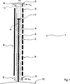
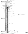
Parallel zu dem Führungsrohr
In
Entsprechen die dargestellten Reed-Kontaktelemente
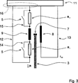
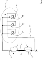
Die zweite Schaltungsanordnung
Durch die Einbindung der Reed-Kontaktelemente
Es versteht sich, dass die Schaltbilder schematischer Natur sind, und dass die entsprechende Elektronik in der Praxis zusätzliche Komponenten aufweisen würden, die aber für das hier interessierende Funktionsprinzip nicht von ausschlaggebender Bedeutung sind.It is understood that the circuit diagrams are schematic in nature, and that the corresponding electronics in practice would have additional components, but which are not of decisive importance for the functional principle of interest here.
BezugszeichenlisteLIST OF REFERENCE NUMBERS
- 11
- StellungsmesssystemPosition measuring system
- 22
- Führsystemguidance system
- 33
- Führstab, SteuerstabGuide rod, control rod
- 44
- Führungsrohrguide tube
- 55
- Sensorelement, Kontaktsensor, Reed-KontaktelementSensor element, contact sensor, reed contact element
- 66
- Reed-KontaktelementReed-contact element
- 77
- Magnetelement, PermanentmagnetMagnetic element, permanent magnet
- 88th
- elektrische Spuleelectric coil
- 99
- Induktionsspuleinduction coil
- 1010
- Druckwandpressure wall
- 1111
- Steuereinheitcontrol unit
- 1212
- erste Schaltungsanordnungfirst circuit arrangement
- 1313
- zweite Schaltungsanordnungsecond circuit arrangement
- 1414
- erste Schaltungsschleifefirst circuit loop
- 1515
- zweite Schaltungsschleifesecond circuit loop
- 1616
- Schaltungsgruppecircuit group
- 1717
- Stromquellepower source
- 1818
- erste Messeinheitfirst measuring unit
- 1919
- zweite Messeinheitsecond measuring unit
- xx
- geradliniger Wegstraightforward way
- xmin x min
- Extremalposition, minimale AusfahrpositionExtremal position, minimum extension position
- xmax x max
- Extremalposition, maximale AusfahrpositionExtremal position, maximum extension position
- x0 x 0
- Referenzpunktreference point
- Ux U x
- Umgebung des geradlinigen WegesSurroundings of the linear path
- HH
- Magnetfeldmagnetic field
- R1 R 1
- erste ohmsche Widerstandseinheitfirst ohmic resistance unit
- R2 R 2
- zweite ohmsche Widerstandseinheitsecond ohmic resistance unit
- ΣR.sigma..sub.r
- Gesamtwiderstand, WiderstandssummeTotal resistance, resistance sum
- IAC I AC
- Wechselstromalternating current
- IDC I DC
- Gleichstromdirect current
- UU
- Gesamtspannungtotal voltage
- UAC U AC
- Wechselspannung, WechselspannungsanteilAC voltage, AC voltage component
- UDC U DC
- Gleichspannung, GleichspannungsanteilDC voltage, DC voltage component
- LL
- Induktivitätinductance
Claims (11)
Priority Applications (12)
| Application Number | Priority Date | Filing Date | Title |
|---|---|---|---|
| DE102010050765A DE102010050765B9 (en) | 2010-11-10 | 2010-11-10 | Position measuring system for detecting an excellent position of a linearly movable guide element |
| BR112013011748A BR112013011748A2 (en) | 2010-11-10 | 2011-10-24 | Position gauge system and associated measurement process for detecting a drawn position of a moving conductor element |
| US13/884,737 US9151591B2 (en) | 2010-11-10 | 2011-10-24 | Position measuring system and associated measuring method for detecting an indicated position of a linearly movable guide element |
| JP2013538089A JP5698850B2 (en) | 2010-11-10 | 2011-10-24 | POSITION MEASUREMENT SYSTEM FOR DETECTING CHARACTERISTIC POSITION OF LINEAR MOVABLE GUIDE ELEMENT AND MEASUREMENT METHOD Attached To It |
| PCT/EP2011/005349 WO2012062409A1 (en) | 2010-11-10 | 2011-10-24 | Position measuring system and associated measuring method for detecting an indicated position of a linearly movable guide element |
| KR1020137014558A KR101532196B1 (en) | 2010-11-10 | 2011-10-24 | Position measuring system and associated measuring method for detecting an indicated position of a linearly movable guide element |
| CN201180053800.4A CN103282744B (en) | 2010-11-10 | 2011-10-24 | For detecting position measuring system and the relevant measurement method of the extrusion position of linearly displaceable induction element |
| RU2013126508/28A RU2553718C2 (en) | 2010-11-10 | 2011-10-24 | Position measurement system and respective method of measurement for determination of marked position of linear mobile guiding element |
| ES11788031.0T ES2457270T3 (en) | 2010-11-10 | 2011-10-24 | Position measurement system for the detection of a relevant position of a guidance element that moves linearly |
| EP11788031.0A EP2638365B1 (en) | 2010-11-10 | 2011-10-24 | Position measuring system for detecting an indicated position of a linearly movable guide element |
| ARP110104156A AR083790A1 (en) | 2010-11-10 | 2011-11-08 | POSITION AND CORRESPONDING MEASUREMENT SYSTEM MEASUREMENT PROCEDURE TO DETECT A HIGHLIGHTED POSITION OF A GUIDE ELEMENT THAT CAN BE MOVED IN LINEAR SENSE |
| ZA2013/02289A ZA201302289B (en) | 2010-11-10 | 2013-03-27 | Position measureing system and associated measuring method for detecting an indicated position of a linearly movable guide element |
Applications Claiming Priority (1)
| Application Number | Priority Date | Filing Date | Title |
|---|---|---|---|
| DE102010050765A DE102010050765B9 (en) | 2010-11-10 | 2010-11-10 | Position measuring system for detecting an excellent position of a linearly movable guide element |
Publications (3)
| Publication Number | Publication Date |
|---|---|
| DE102010050765A1 DE102010050765A1 (en) | 2012-05-10 |
| DE102010050765B4 DE102010050765B4 (en) | 2012-11-08 |
| DE102010050765B9 true DE102010050765B9 (en) | 2013-08-29 |
Family
ID=45044490
Family Applications (1)
| Application Number | Title | Priority Date | Filing Date |
|---|---|---|---|
| DE102010050765A Expired - Fee Related DE102010050765B9 (en) | 2010-11-10 | 2010-11-10 | Position measuring system for detecting an excellent position of a linearly movable guide element |
Country Status (12)
| Country | Link |
|---|---|
| US (1) | US9151591B2 (en) |
| EP (1) | EP2638365B1 (en) |
| JP (1) | JP5698850B2 (en) |
| KR (1) | KR101532196B1 (en) |
| CN (1) | CN103282744B (en) |
| AR (1) | AR083790A1 (en) |
| BR (1) | BR112013011748A2 (en) |
| DE (1) | DE102010050765B9 (en) |
| ES (1) | ES2457270T3 (en) |
| RU (1) | RU2553718C2 (en) |
| WO (1) | WO2012062409A1 (en) |
| ZA (1) | ZA201302289B (en) |
Cited By (1)
| Publication number | Priority date | Publication date | Assignee | Title |
|---|---|---|---|---|
| DE102014006276A1 (en) * | 2014-05-02 | 2015-11-05 | Meas Deutschland Gmbh | Measuring device and method for measuring the level of a liquid in a container |
Families Citing this family (16)
| Publication number | Priority date | Publication date | Assignee | Title |
|---|---|---|---|---|
| DE102013219657A1 (en) * | 2013-09-27 | 2015-04-02 | Continental Teves Ag & Co. Ohg | Method for testing a transformer |
| DE102015200619A1 (en) * | 2015-01-16 | 2016-07-21 | Zf Friedrichshafen Ag | Inductive position determination |
| KR101634707B1 (en) * | 2015-02-13 | 2016-06-30 | 한국원자력연구원 | Magnetostrictive wire control rod position indicator |
| CN104751919B (en) * | 2015-03-03 | 2017-05-31 | 美核电气(济南)股份有限公司 | Nuclear power control stick position display system and its anti-interference display methods |
| KR101659822B1 (en) * | 2015-10-16 | 2016-09-26 | 주식회사 우진 | Control rod position indicator for nuclear reactor and method thereof |
| CN105353058A (en) * | 2015-11-02 | 2016-02-24 | 上海盛拓医疗器械有限公司 | Automatic reversing liquid phase injection pump |
| US10775199B2 (en) | 2016-08-24 | 2020-09-15 | Mitutoyo Corporation | Winding and scale configuration for inductive position encoder |
| DE102017205472A1 (en) * | 2017-03-31 | 2018-10-04 | Robert Bosch Gmbh | Sensor arrangement for non-contact linear position detection |
| CN107833643B (en) * | 2017-10-16 | 2019-05-24 | 中核核电运行管理有限公司 | Totally digitilized rod position measuring device and its method |
| JP7154990B2 (en) * | 2017-12-21 | 2022-10-18 | 株式会社ミツトヨ | Winding and scale configuration of electromagnetic induction encoder |
| CN109920569B (en) * | 2019-03-15 | 2020-10-13 | 中广核核电运营有限公司 | Addressing device and method for nuclear power station reactor control rods |
| DE102019205502A1 (en) * | 2019-04-16 | 2020-10-22 | Zf Active Safety Gmbh | Level sensing device |
| DE102019115179A1 (en) * | 2019-06-05 | 2020-12-10 | Krones Ag | Device for monitoring containers and methods for positioning sensors |
| WO2020253956A1 (en) * | 2019-06-19 | 2020-12-24 | Framatome Gmbh | Control rod position indication system for a nuclear reactor |
| CN111951989B (en) * | 2020-08-13 | 2022-06-17 | 中国核动力研究设计院 | Method and system for intelligently calibrating rod position measurement parameters |
| CN112071456A (en) * | 2020-09-15 | 2020-12-11 | 中国核动力研究设计院 | Rod position detector for nuclear reactor control rod drive mechanism and use method thereof |
Citations (4)
| Publication number | Priority date | Publication date | Assignee | Title |
|---|---|---|---|---|
| DE2719933A1 (en) * | 1976-05-05 | 1977-11-10 | Diamond Power Speciality | DISPLAY DEVICE FOR DETERMINING THE POSITION OF A MOVABLE PART WITHIN A SEALED CONTAINER |
| DE19548509A1 (en) * | 1995-12-22 | 1997-07-03 | Siemens Ag | Method and device for determining the position of a control rod of a nuclear power plant |
| DE20009155U1 (en) * | 2000-05-20 | 2000-08-24 | Festo Ag & Co | Position detection device and adjusting device equipped therewith |
| DE102004041107A1 (en) * | 2004-03-08 | 2005-10-06 | Micro-Epsilon Messtechnik Gmbh & Co Kg | Non-contact position measuring system |
Family Cites Families (14)
| Publication number | Priority date | Publication date | Assignee | Title |
|---|---|---|---|---|
| US3048818A (en) * | 1957-07-22 | 1962-08-07 | Schweiz Wagons Aufzuegefab | Position indicator |
| US3594740A (en) * | 1967-08-10 | 1971-07-20 | Combustion Eng | Position indicating apparatus |
| US3656074A (en) * | 1968-11-14 | 1972-04-11 | Combustion Eng | Control rod position transmitter |
| GB1347329A (en) | 1971-01-27 | 1974-02-27 | Westinghouse Electric Corp | Magnetic position indicator |
| US3906469A (en) * | 1973-06-12 | 1975-09-16 | Combustion Eng | Magnetic-electric position sensor |
| US4014741A (en) | 1975-07-11 | 1977-03-29 | Diamond Power Specialty Corporation | Nuclear control rod position indicating assembly |
| US4068163A (en) * | 1976-07-02 | 1978-01-10 | Diamond Power Specialty Corporation | Reed switch oscillator assembly for a position indicating system |
| FR2523719B1 (en) * | 1982-03-17 | 1985-09-13 | Merlin Gerin | POSITION DETECTOR OF A MOBILE ELEMENT, IN PARTICULAR OF A CONTROL BAR OF A NUCLEAR REACTOR |
| RU1806410C (en) | 1990-04-23 | 1993-03-30 | Опытное Конструкторское Бюро "Гидропресс" | Position monitoring system for nuclear reactor control element |
| DE4208888B4 (en) * | 1992-03-19 | 2007-06-06 | Zf Sachs Ag | Arrangement for detecting the gear position of a motor vehicle gearbox |
| DE20116564U1 (en) * | 2001-10-09 | 2002-01-17 | Festo Ag & Co | Position sensing device |
| US6571626B1 (en) | 2001-10-11 | 2003-06-03 | Walbro Corporation | Fuel level sensor |
| CN100592036C (en) | 2004-03-08 | 2010-02-24 | 微一埃普西龙测量技术有限两合公司 | Contactless displacement measuring system |
| DE102007031382A1 (en) | 2007-06-26 | 2009-01-08 | Hengst Gmbh & Co.Kg | Fuel filter with filter recognition |
-
2010
- 2010-11-10 DE DE102010050765A patent/DE102010050765B9/en not_active Expired - Fee Related
-
2011
- 2011-10-24 US US13/884,737 patent/US9151591B2/en not_active Expired - Fee Related
- 2011-10-24 CN CN201180053800.4A patent/CN103282744B/en not_active Expired - Fee Related
- 2011-10-24 JP JP2013538089A patent/JP5698850B2/en not_active Expired - Fee Related
- 2011-10-24 RU RU2013126508/28A patent/RU2553718C2/en not_active IP Right Cessation
- 2011-10-24 KR KR1020137014558A patent/KR101532196B1/en not_active IP Right Cessation
- 2011-10-24 BR BR112013011748A patent/BR112013011748A2/en not_active Application Discontinuation
- 2011-10-24 EP EP11788031.0A patent/EP2638365B1/en not_active Not-in-force
- 2011-10-24 WO PCT/EP2011/005349 patent/WO2012062409A1/en active Application Filing
- 2011-10-24 ES ES11788031.0T patent/ES2457270T3/en active Active
- 2011-11-08 AR ARP110104156A patent/AR083790A1/en not_active Application Discontinuation
-
2013
- 2013-03-27 ZA ZA2013/02289A patent/ZA201302289B/en unknown
Patent Citations (4)
| Publication number | Priority date | Publication date | Assignee | Title |
|---|---|---|---|---|
| DE2719933A1 (en) * | 1976-05-05 | 1977-11-10 | Diamond Power Speciality | DISPLAY DEVICE FOR DETERMINING THE POSITION OF A MOVABLE PART WITHIN A SEALED CONTAINER |
| DE19548509A1 (en) * | 1995-12-22 | 1997-07-03 | Siemens Ag | Method and device for determining the position of a control rod of a nuclear power plant |
| DE20009155U1 (en) * | 2000-05-20 | 2000-08-24 | Festo Ag & Co | Position detection device and adjusting device equipped therewith |
| DE102004041107A1 (en) * | 2004-03-08 | 2005-10-06 | Micro-Epsilon Messtechnik Gmbh & Co Kg | Non-contact position measuring system |
Cited By (2)
| Publication number | Priority date | Publication date | Assignee | Title |
|---|---|---|---|---|
| DE102014006276A1 (en) * | 2014-05-02 | 2015-11-05 | Meas Deutschland Gmbh | Measuring device and method for measuring the level of a liquid in a container |
| US10656004B2 (en) | 2014-05-02 | 2020-05-19 | TE Connectivity Sensors Germany GmbH | Measuring device and method for measuring the level of a liquid in a container |
Also Published As
| Publication number | Publication date |
|---|---|
| AR083790A1 (en) | 2013-03-20 |
| DE102010050765A1 (en) | 2012-05-10 |
| WO2012062409A1 (en) | 2012-05-18 |
| KR20130129214A (en) | 2013-11-27 |
| RU2553718C2 (en) | 2015-06-20 |
| US20130271120A1 (en) | 2013-10-17 |
| JP5698850B2 (en) | 2015-04-08 |
| BR112013011748A2 (en) | 2016-09-13 |
| EP2638365B1 (en) | 2014-03-12 |
| ES2457270T3 (en) | 2014-04-25 |
| DE102010050765B4 (en) | 2012-11-08 |
| JP2013545099A (en) | 2013-12-19 |
| RU2013126508A (en) | 2014-12-20 |
| US9151591B2 (en) | 2015-10-06 |
| ZA201302289B (en) | 2013-12-23 |
| KR101532196B1 (en) | 2015-06-29 |
| CN103282744A (en) | 2013-09-04 |
| EP2638365A1 (en) | 2013-09-18 |
| CN103282744B (en) | 2016-08-10 |
Similar Documents
| Publication | Publication Date | Title |
|---|---|---|
| DE102010050765B9 (en) | Position measuring system for detecting an excellent position of a linearly movable guide element | |
| DE102013014456A1 (en) | Actuator of a safety switch and safety switch with such an actuator | |
| EP2375085A1 (en) | Actuating device for adjusting an actuator and method for determining the position of the actuator | |
| EP1261131B1 (en) | Inductive gear switching unit | |
| DE4142996A1 (en) | METHOD FOR MEASURING THE MECHANICAL MOVEMENT OF A SOLENOID VALVE ARMOR, ESPECIALLY ELECTRICALLY CONTROLLED INJECTION SYSTEMS | |
| EP2684009B1 (en) | Apparatus for detecting a magnetically conductive object and position measuring system for measuring the position of a guide rod and associated position measuring method | |
| EP0814321B1 (en) | Inductive displacement sensor | |
| DE3201977A1 (en) | DEVICE FOR MEASURING MECHANICAL SIZES OF A WORKPIECE | |
| EP2862744A2 (en) | Method and device for monitoring a return cable of a rail track | |
| DE102013200698A1 (en) | Coil arrangement with two coils | |
| EP3673231B1 (en) | Inductive sensor | |
| WO2003062741A2 (en) | Path sensor with an magnetoelectric transformer element | |
| DE102012005344B4 (en) | TOUCH-FREE CONTACTOR ACCORDING TO THE PLCD PRINCIPLE | |
| EP2803071A1 (en) | Device for measuring the position of a movable control rod in a nuclear reactor | |
| DE102012204321A1 (en) | Electromagnetic actuator suitable for armature position detection | |
| EP3070436B1 (en) | Position measuring system with calibration means | |
| EP3067604A1 (en) | Return valve | |
| DE10258254A1 (en) | Displacement sensor with magnetoelectric transducer element | |
| EP1981156A2 (en) | Electric linear drive device | |
| DE102006044779B4 (en) | Device for detecting a force and / or a torque | |
| DE3316209C2 (en) | ||
| DE3527004C2 (en) | ||
| EP2317285B1 (en) | Sensor device | |
| DE102013114073B3 (en) | Auxiliary switch for a switching device | |
| DE102012015200A1 (en) | Inductive proximity switch for detecting metallic targets in monitoring area, comprises transmitter coil that is cylindrical coil and receiving coil that is sheet-shaped coil, whose coil surface runs parallel to surface of transmitter coil |
Legal Events
| Date | Code | Title | Description |
|---|---|---|---|
| R016 | Response to examination communication | ||
| R016 | Response to examination communication | ||
| R018 | Grant decision by examination section/examining division | ||
| R020 | Patent grant now final |
Effective date: 20130209 |
|
| R082 | Change of representative |
Representative=s name: TERGAU & WALKENHORST PATENTANWAELTE - RECHTSAN, DE |
|
| R081 | Change of applicant/patentee |
Owner name: AREVA GMBH, DE Free format text: FORMER OWNER: AREVA NP GMBH, 91052 ERLANGEN, DE Effective date: 20130618 |
|
| R082 | Change of representative |
Representative=s name: TERGAU & WALKENHORST PATENTANWAELTE PARTGMBB, DE Effective date: 20130618 Representative=s name: TERGAU & WALKENHORST PATENTANWAELTE - RECHTSAN, DE Effective date: 20130618 |
|
| R119 | Application deemed withdrawn, or ip right lapsed, due to non-payment of renewal fee |