GEBIET DER ERFINDUNGFIELD OF THE INVENTION
Die vorliegende Offenbarung betrifft ein Brennstoffzellensystem und ein Verfahren zum Starten eines Brennstoffzellensystems.The present disclosure relates to a fuel cell system and a method for starting a fuel cell system.
HINTERGRUND DER ERFINDUNGBACKGROUND OF THE INVENTION
Eine Brennstoffzelle ist als eine reine, effiziente und umweltfreundliche Energiequelle für Elektrofahrzeuge und verschiedene andere Anwendungen vorgeschlagen worden. Insbesondere ist die Brennstoffzelle als eine potenzielle Alternative für die herkömmlichen Brennkraftmaschinen, die in modernen Fahrzeugen verwendet werden, erkannt worden.A fuel cell has been proposed as a pure, efficient and environmentally friendly power source for electric vehicles and various other applications. In particular, the fuel cell has been recognized as a potential alternative to the conventional internal combustion engines used in modern vehicles.
Ein Typ einer Brennstoffzelle ist als eine Protonenaustauschmembran(PEM)-Brennstoffzelle bekannt. Die PEM-Brennstoffzelle umfasst typischerweise drei Grundkomponenten: eine Kathodenelektrode, eine Anodenelektrode und eine Elektrolytmembran. Die Kathoden- und Anodenelektroden weisen typischerweise einen fein geteilten Katalysator, wie Platin auf, der auf Kohlenstoffpartikeln geträgert und mit einem Ionomer gemischt ist. Die Elektrolytmembran ist schichtartig zwischen der Kathode- und der Anode angeordnet, um eine Membranelektrodenanordnung (MEA) zu bilden. Die MEA ist oftmals zwischen porösen Diffusionsmedien (DM) angeordnet, die eine Lieferung von gasförmigen Reaktanden, typischerweise Wasserstoff und Sauerstoff, für eine elektrochemische Brennstoffzellenreaktion fördern. Solch eine Brennstoffzelle ist beispielsweise aus der DE 11 2004 002 565 T5 bekannt geworden. Gemäß der Lehre dieser Druckschrift wird beim Starten der Brennstoffzelle über den Anodenauslass der Brennstoffzelle ein Vakuum im Bereich des Anodenströmungsfelds der Zelle erzeugt.One type of fuel cell is known as a proton exchange membrane (PEM) fuel cell. The PEM fuel cell typically includes three basic components: a cathode electrode, an anode electrode and an electrolyte membrane. The cathode and anode electrodes typically comprise a finely divided catalyst, such as platinum, supported on carbon particles and mixed with an ionomer. The electrolyte membrane is sandwiched between the cathode and the anode to form a membrane electrode assembly (MEA). The MEA is often located between porous diffusion media (DM) which promote delivery of gaseous reactants, typically hydrogen and oxygen, for a fuel cell electrochemical reaction. Such a fuel cell is for example from DE 11 2004 002 565 T5 known. According to the teaching of this document, a vacuum is generated in the region of the anode flow field of the cell when starting the fuel cell via the anode outlet of the fuel cell.
Einzelne Brennstoffzellen können gemeinsam in Reihe gestapelt werden, um einen Brennstoffzellenstapel zu bilden. Bei Inbetriebnahme des Brennstoffzellenstapels wird typischerweise Wasserstoffgas dazu verwendet, um die Anoden von Luft zu spülen, die während des Abschaltens in die Anoden diffundiert ist und sich in diesen ansammelt. Das Strömen von Wasserstoffgas in die Anoden nach einer Abschaltung erzeugt eine ”Wasserstoff-Luft-Front”, die über die Anoden gelangt. Die Spülung ist erwünschtermaßen rasch, um den bekannten Kohlenstoffabbau zu minimieren, der auftritt, wenn sich die Wasserstoff-Luft-Front über die Anoden bewegt, während sich Luft an den Kathoden befindet. Ein herkömmliches Brennstoffzellensystem verwendet hauptsächlich den Wasserstoffgasdruck während des Spülens, um die angesammelte Luft zu verdrängen. Jedoch kann die Füllrate durch Druckbeschränkungen des Brennstoffzellenstapels wie auch Strömungswiderstände über das Brennstoffzellensystem beschränkt sein.Individual fuel cells may be stacked together in series to form a fuel cell stack. Hydrogen gas is typically used to start up the fuel cell stack to purge the anodes of air that has diffused into and accumulates in the anodes during shutdown. The flow of hydrogen gas into the anodes after shutdown creates a "hydrogen-air front" that passes over the anodes. The purge is desirably rapid to minimize the known carbon degradation that occurs as the hydrogen-air front moves over the anodes while air is at the cathodes. A conventional fuel cell system mainly uses the hydrogen gas pressure during purging to displace the accumulated air. However, the fill rate may be limited by pressure limitations of the fuel cell stack as well as flow resistances across the fuel cell system.
Um einen Kohlenstoffabbau zu mindern, wird manchmal während des Spülens ein Kurzschluss des Brennstoffzellenstapels ausgeführt. Jedoch kann eine Kohlenstoffkorrosion auch durch eine nicht gleichzeitige Lieferung von Wasserstoff zu den Brennstoffzellen bewirkt werden. Beispielsweise können die der Wasserstoffversorgung am nächsten liegenden Brennstoffzellen Wasserstoff zuerst aufnehmen, und der Kurzschluss wirkt so lange nicht, bis der größte Teil der Brennstoffzellen Wasserstoff aufgenommen hat. Somit können die Brennstoffzellen, die den Wasserstoff zuerst aufnehmen, aufgrund der Wasserstoff-Luft-Front einer ungeminderten Korrosion ausgesetzt sein. Zusätzlich beginnt, wenn viele der Brennstoffzellen beginnen, Wasserstoff aufzunehmen, der Kurzschluss wirksam zu werden. Jedoch können die Brennstoffzellen, die keinen Wasserstoff aufweisen, bei einem Phänomen, das als eine ”Zellenumkehr” bzw. ”Zellenumpolung” bekannt ist, einer negativen Spannung ausgesetzt werden. Eine Zellenumkehr resultiert auch in einer unerwünschten Kohlenstoffkorrosion des Brennstoffzellenstapels.In order to reduce carbon degradation, a short circuit of the fuel cell stack is sometimes performed during purging. However, carbon corrosion may also be caused by non-simultaneous delivery of hydrogen to the fuel cells. For example, the fuel cells closest to the hydrogen supply may first receive hydrogen, and the short circuit will not work until most of the fuel cells have taken up hydrogen. Thus, the fuel cells that first receive the hydrogen may experience undiminished corrosion due to the hydrogen-air front. In addition, when many of the fuel cells start to take up hydrogen, the short circuit starts to take effect. However, the non-hydrogen fuel cells may be subjected to negative voltage in a phenomenon known as "cell reversal" or "cell reversal". Cell reversal also results in undesirable carbon corrosion of the fuel cell stack.
Bei Inbetriebnahme wird auch Luft an einen Austrag eines Brennstoffzellenstapels umgeleitet, um den ausgetragenen reinen Wasserstoff zu verdünnen. Fahrzeugemissionsstandards erfordern allgemein, dass die Konzentration von ausgetragenem Wasserstoff kleiner als vier Volumenprozent (4 Vol.-%) ist. Bekannte Brennstoffzellensysteme sind jedoch aufgrund der inkonsistenten Bedingungen des Brennstoffzellensystems nach einer Abschaltperiode, wie einer variablen Menge von angesammelter Luft an den Anoden, bei einer Optimierung von Wasserstoffemissionen bei Inbetriebnahme nicht besonders wirkungsvoll.At startup, air is also diverted to a discharge of a fuel cell stack to dilute the discharged pure hydrogen. Vehicle emission standards generally require that the concentration of hydrogen discharged is less than four percent by volume (4% by volume). However, known fuel cell systems are not particularly effective at optimizing startup hydrogen emissions due to the inconsistent conditions of the fuel cell system after a shutdown period, such as a variable amount of accumulated air at the anodes.
Daher existiert ein fortwährender Bedarf nach einem Brennstoffzellensystem und einem Verfahren, die eine effiziente Inbetriebnahme bereitstellen, während erwünschte Wasserstoffaustragsemissionsstandards erfüllt werden. Erwünschtermaßen sehen das Brennstoffzellensystem wie auch die Verfahren eine rasche Systeminbetriebnahme mit einer minimalen Stapeldegradation durch Optimierung der Wasserstoff-Luft-Frontzeit während der Inbetriebnahme vor.Therefore, there is a continuing need for a fuel cell system and method that provides efficient startup while meeting desired hydrogen emission standards. Desirably, the fuel cell system as well as the methods provide for rapid system start-up with minimal stack degradation by optimizing the hydrogen-air front time during commissioning.
ZUSAMMENFASSUNG DER ERFINDUNGSUMMARY OF THE INVENTION
Gemäß der vorliegenden Offenbarung sind ein Brennstoffzellensystem und ein Verfahren entwickelt worden, die eine effiziente Inbetriebnahme bereitstellen, die Wasserstoffaustragsemissionsstandards erfüllt und eine Wasserstoff-Luft-Frontzeit sowie eine Stapeldegradation minimiert.In accordance with the present disclosure, a fuel cell system and method have been developed that provide efficient start-up that meets hydrogen emission emission standards and minimizes hydrogen-air front time and stack degradation.
Bei einer Ausführungsform umfasst ein Brennstoffzellensystem die Merkmale des Anspruchs 1. In one embodiment, a fuel cell system comprises the features of claim 1.
Bei einer anderen Ausführungsform umfasst ein erstes Verfahren zum Starten des Brennstoffzellensystems den Schritt, dass der Brennstoffzellenstapel mit dem Anodenversorgungsverteiler in Fluidkommunikation mit einem ersten Spülventil und einem Anodeneinlassventil bereitgestellt wird, das derart ausgebildet ist, um Wasserstoff selektiv an den Anodenversorgungsverteiler zu liefern. Der Anodenaustragsverteiler steht in Fluidkommunikation mit einem Anodenauslassventil. Eine Saugvorrichtung in Fluidkommunikation mit dem ersten Spülventil und dem Anodenauslassventil ist ebenfalls vorgesehen. Das erste Verfahren umfasst ferner die Schritte, dass: ein Teilvakuum an dem Brennstoffzellenstapel erzeugt wird, indem das erste Spülventil und das Anodenauslassventil geöffnet werden; das Anodenauslassventil geschlossen wird; der Anodenversorgungsverteiler mit Wasserstoff durch Öffnen des Anodeneinlassventils gespült wird; das erste Spülventil geschlossen wird, wenn der Anodenversorgungsverteiler im Wesentlichen mit Wasserstoff gefüllt ist; die Anoden und der Anodenaustragsverteiler mit Wasserstoff durch Öffnen des Anodenauslassventils versorgt werden; und die Kathoden mit Luft versorgt werden. Der Brennstoffzellenstapel wird dadurch in einen Betriebsmodus versetzt.In another embodiment, a first method of starting the fuel cell system includes the step of providing the fuel cell stack with the anode supply manifold in fluid communication with a first purge valve and an anode inlet valve configured to selectively supply hydrogen to the anode supply manifold. The anode exhaust manifold is in fluid communication with an anode exhaust valve. A suction device in fluid communication with the first purge valve and the anode exhaust valve is also provided. The first method further comprises the steps of: creating a partial vacuum on the fuel cell stack by opening the first purge valve and the anode exhaust valve; the anode exhaust valve is closed; purging the anode supply manifold with hydrogen by opening the anode inlet valve; the first purge valve is closed when the anode supply manifold is substantially filled with hydrogen; supplying the anodes and the anode discharge manifold with hydrogen by opening the anode exhaust valve; and the cathodes are supplied with air. The fuel cell stack is thereby placed in an operating mode.
Bei einer weiteren Ausführungsform umfasst ein zweites Verfahren zum Starten des Brennstoffzellensystems den Schritt, dass der Brennstoffzellenstapel mit dem Anodenversorgungsverteiler in Fluidkommunikation mit einem ersten Spülventil und einem Anodeneinlassventil bereitgestellt wird, das derart ausgebildet ist, um Wasserstoff selektiv an den Anodenversorgungsverteiler zu liefern. Der Anodenaustragsverteiler steht in Fluidkommunikation mit einem zweiten Spülventil und einem Anodenauslassventil. Es ist auch eine Saugvorrichtung in Fluidkommunikation mit dem ersten Spülventil und dem zweiten Spülventil vorgesehen. Das zweite Verfahren umfasst ferner die Schritte, dass: ein Teilvakuum an dem Anodenversorgungsverteiler durch Öffnen des ersten Spülventils erzeugt wird; der Anodenversorgungsverteiler mit Wasserstoff durch Öffnen des Anodeneinlassventils gespült wird; das erste Spülventil geschlossen wird, wenn der Anodenversorgungsverteiler im Wesentlichen mit Wasserstoff gefüllt ist; ein Teilvakuum an dem Anodenaustragsverteiler durch Öffnen des zweiten Spülventils und des Anodenauslassventils erzeugt wird, wobei die Anoden und der Anodenaustragsverteiler mit Wasserstoff versorgt werden; das zweite Spülventil geschlossen wird, wenn die Anoden im Wesentlichen mit Wasserstoff gefüllt sind; und die Kathoden des Brennstoffzellenstapels mit Luft versorgt werden. Das Brennstoffzellensystem wird dadurch in einen Betriebsmodus versetzt.In another embodiment, a second method of starting the fuel cell system includes the step of providing the fuel cell stack with the anode supply manifold in fluid communication with a first purge valve and an anode inlet valve configured to selectively supply hydrogen to the anode supply manifold. The anode exhaust manifold is in fluid communication with a second purge valve and an anode exhaust valve. There is also provided a suction device in fluid communication with the first purge valve and the second purge valve. The second method further comprises the steps of: creating a partial vacuum on the anode supply manifold by opening the first purge valve; purging the anode supply manifold with hydrogen by opening the anode inlet valve; the first purge valve is closed when the anode supply manifold is substantially filled with hydrogen; a partial vacuum is generated at the anode discharge manifold by opening the second purge valve and the anode exhaust valve, wherein the anodes and the anode exhaust manifold are supplied with hydrogen; the second purge valve is closed when the anodes are substantially filled with hydrogen; and the cathodes of the fuel cell stack are supplied with air. The fuel cell system is thereby placed in an operating mode.
ZEICHNUNGENDRAWINGS
Die obigen wie auch andere Vorteile der vorliegenden Offenbarung werden dem Fachmann leicht aus der folgenden detaillierten Beschreibung insbesondere unter Bezugnahme auf die nachfolgend beschriebenen Zeichnungen offensichtlich, in welchen:The above as well as other advantages of the present disclosure will be readily apparent to those skilled in the art from the following detailed description, in particular with reference to the drawings described below, in which:
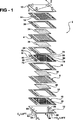
1 eine schematische, perspektivische Explosionsdarstellung eines PEM-Brennstoffzellenstapels der vorliegenden Erfindung veranschaulicht, die nur zwei Zellen zeigt; 1 Fig. 3 illustrates a schematic exploded perspective view of a PEM fuel cell stack of the present invention showing only two cells;
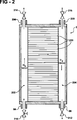
2 eine schematische Schnittansicht des in 1 gezeigten Brennstoffzellenstapels ist, die eine Vielzahl von Brennstoffzellen in Fluidkommunikation mit einem Einlassventil, einem Auslassventil und Spülventilen zeigt; 2 a schematic sectional view of the in 1 10 is a fuel cell stack showing a plurality of fuel cells in fluid communication with an intake valve, an exhaust valve, and purge valves;
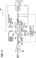
3 ein schematisches Flussdiagramm eines Brennstoffzellensystems gemäß einer Ausführungsform der vorliegenden Offenbarung; 3 a schematic flowchart of a fuel cell system according to an embodiment of the present disclosure;
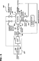
4 ein schematisches Flussdiagramm des in 3 gezeigten Brennstoffzellensystems mit einem Ejektor ist, der derart ausgebildet ist, um eine Anodenspülung des Brennstoffzellensystems zu unterstützen; und 4 a schematic flow diagram of the in 3 shown fuel cell system with an ejector, which is designed to assist an anode scavenging of the fuel cell system; and
5 ein schematisches Flussdiagramm des in 3 gezeigten Brennstoffzellensystems mit einem Luftkompressor und einem Strömungsbegrenzer ist, der derart ausgebildet ist, um eine Anodenspülung des Brennstoffzellensystems zu unterstützen. 5 a schematic flow diagram of the in 3 shown fuel cell system with an air compressor and a flow limiter, which is designed so as to support an anode scavenging of the fuel cell system.
DETAILLIERTE BESCHREIBUNG DER ERFINDUNGDETAILED DESCRIPTION OF THE INVENTION
Die folgende Beschreibung ist lediglich beispielhafter Natur. Es sei auch zu verstehen, dass entsprechende Bezugszeichen in allen Zeichnungen gleiche oder entsprechende Teile und Merkmale angeben. In Bezug auf die offenbarten Verfahren sind die dargestellten Schritte lediglich beispielhafter Natur und somit nicht notwendig oder kritisch.The following description is merely exemplary in nature. It should also be understood that like reference numbers indicate the same or corresponding parts and features throughout the drawings. With respect to the disclosed methods, the illustrated steps are merely exemplary in nature and thus not necessary or critical.
1 zeigt einen Brennstoffzellenstapel 2 mit einem Paar von MEAs 4, 6, die voneinander durch eine elektrisch leitende Bipolarplatte 8 getrennt sind. Der Einfachheit halber ist in 1 nur ein zwei Zellen umfassender Stapel (d. h. eine Bipolarplatte) veranschaulicht und beschrieben, wobei zu verstehen sei, dass ein typischer Brennstoffzellenstapel viel mehr derartige Zellen und Bipolarplatten besitzt. 1 shows a fuel cell stack 2 with a pair of MEAs 4 . 6 separated by an electrically conductive bipolar plate 8th are separated. For the sake of simplicity, is in 1 only a two-cell stack (ie, a bipolar plate) is illustrated and described, it being understood that a typical fuel cell stack has many more such cells and bipolar plates.
Die MEAs 4, 6 und die Bipolarplatte 8 sind zwischen einem Paar von Klemmplatten 10, 12 und einem Paar von unipolaren Endplatten 14, 16 aneinander gestapelt. Die Klemmplatten 10, 12 sind durch ein Dichtungselement oder eine dielektrische Beschichtung (nicht gezeigt) elektrisch von den Endplatten 14, 16 isoliert. Die unipolaren Endplatten 14, beide Arbeitsseiten der Bipolarplatte 8 und die unipolare Endplatte 16 weisen Strömungsfelder 18, 20, 22, 24 auf. Die Strömungsfelder 18, 20, 22, 24 verteilen Wasserstoffgas und Luft über eine Anode bzw. eine Kathode der MEAs 4, 6. The MEAs 4 . 6 and the bipolar plate 8th are between a pair of clamping plates 10 . 12 and a pair of unipolar endplates 14 . 16 stacked together. The clamping plates 10 . 12 are electrically from the end plates by a sealing member or a dielectric coating (not shown) 14 . 16 isolated. The unipolar end plates 14 , both working sides of the bipolar plate 8th and the unipolar endplate 16 have flow fields 18 . 20 . 22 . 24 on. The flow fields 18 . 20 . 22 . 24 distribute hydrogen gas and air via an anode or a cathode of the MEAs 4 . 6 ,
Nichtleitende Dichtungselemente 26, 28, 30, 32 sehen Abdichtungen wie auch eine elektrische Isolierung zwischen den verschiedenen Komponenten des Brennstoffzellenstapels 2 vor. Gaspermeable Diffusionsmedien 34, 36, 38, 40 grenzen an die Anoden und die Kathoden der MEAs 4, 6 an. Die Endplatten 14, 16 sind benachbart den Diffusionsmedien 34 bzw. 40 angeordnet, während die Bipolarplatte 8 benachbart dem Diffusionsmedium 36 an der Anodenseite der MEA 4 angeordnet ist. Die Bipolarplatte 8 ist ferner benachbart dem Diffusionsmedium 38 an der Kathodenseite der MEA 6 angeordnet.Non-conductive sealing elements 26 . 28 . 30 . 32 see seals as well as electrical insulation between the various components of the fuel cell stack 2 in front. Gas permeable diffusion media 34 . 36 . 38 . 40 adjacent to the anodes and cathodes of the MEAs 4 . 6 at. The end plates 14 . 16 are adjacent to the diffusion media 34 respectively. 40 arranged while the bipolar plate 8th adjacent to the diffusion medium 36 on the anode side of the MEA 4 is arranged. The bipolar plate 8th is also adjacent to the diffusion medium 38 on the cathode side of the MEA 6 arranged.
Die Bipolarplatte 8, die unipolaren Endplatten 14, 16 und die Dichtungselemente 26, 28, 30, 32 umfassen jeweils eine Anodenversorgungsöffnung 72 und eine Anodenaustragsöffnung 74, eine Kathodenversorgungsöffnung 76 und eine Kathodenaustragsöffnung 78 und eine Kühlmittelversorgungsöffnung 80 und eine Kühlmittelaustragsöffnung 82. Versorgungsverteiler, Austragsverteiler und Kühlmittelverteiler des Brennstoffzellenstapels 2 werden durch eine Ausrichtung der jeweiligen Öffnungen 72, 74, 76, 78, 80, 82 in der Bipolarplatte 8, den unipolaren Endplatten 14, 16 und den Dichtungselementen 26, 28, 30, 32 geformt.The bipolar plate 8th , the unipolar endplates 14 . 16 and the sealing elements 26 . 28 . 30 . 32 each include an anode supply port 72 and an anode discharge port 74 , a cathode supply port 76 and a cathode discharge port 78 and a coolant supply port 80 and a coolant discharge port 82 , Supply distributor, discharge distributor and coolant distributor of the fuel cell stack 2 be by an orientation of the respective openings 72 . 74 . 76 . 78 . 80 . 82 in the bipolar plate 8th , the unipolar end plates 14 . 16 and the sealing elements 26 . 28 . 30 . 32 shaped.
Die Anodenversorgungsöffnungen 72 und die Anodenaustragsöffnungen 74 stehen in Fluidkommunikation mit einer Anodeneinlassleitung 84 bzw. einer Anodenauslassleitung 86. Eine Kathodeneinlassleitung 88 und eine Kathodenauslassleitung 90 stehen in Fluidkommunikation mit den Kathodenversorgungsöffnungen 76 bzw. den Kathodenaustragsöffnungen 78. Die Kühlmittelversorgungsöffnungen 80 und die Kühlmittelaustragsöffnungen 82 stehen in Fluidkommunikation mit einer Kühlmitteleinlassleitung 92 bzw. einer Kühlmittelauslassleitung 94. Es sei zu verstehen, dass die Ausgestaltungen der verschiedenen Einlässe 84, 88, 92 und Auslässe 86, 90, 94 in 1 zum Zwecke der Veranschaulichung dienen und gegebenenfalls andere Ausgestaltungen gewählt werden können.The anode supply openings 72 and the anode discharge openings 74 are in fluid communication with an anode inlet conduit 84 or an anode outlet line 86 , A cathode inlet line 88 and a cathode exhaust pipe 90 are in fluid communication with the cathode supply ports 76 or the cathode discharge openings 78 , The coolant supply openings 80 and the coolant discharge openings 82 are in fluid communication with a coolant inlet line 92 or a coolant outlet line 94 , It should be understood that the embodiments of the various inlets 84 . 88 . 92 and outlets 86 . 90 . 94 in 1 serve for the purpose of illustration and optionally other configurations can be selected.
Wie in 2 gezeigt ist, kann der Brennstoffzellenstapel 2 eine Vielzahl von Brennstoffzellen 200 aufweisen. Der zusammengebaute Brennstoffzellenstapel 2 besitzt einen Anodenversorgungsverteiler 202 und einen Anodenaustragsverteiler 204. Der Anodenversorgungsverteiler 202 ist derart ausgebildet, um eine Wasserstoffströmung über die Anodeneinlassleitung 84 aufzunehmen und den Wasserstoff an die Anoden der Vielzahl von Brennstoffzellen 200 zu liefern. Der Anodenaustragsverteiler 204 ist derart angepasst, um die Wasserstoffströmung von den Anoden der Vielzahl von Brennstoffzellen 200 aufzunehmen und den Wasserstoff an die Anodenauslassleitung 86 zu liefern. Der Brennstoffzellenstapel 2 kann ferner eine Versorgungsverteilerspülleitung 206 in Fluidkommunikation mit dem Anodenversorgungsverteiler 202 und/oder eine Austragsverteilerspülleitung 208 in Fluidkommunikation mit dem Anodenaustragsverteiler 204 aufweisen.As in 2 is shown, the fuel cell stack 2 a variety of fuel cells 200 exhibit. The assembled fuel cell stack 2 has an anode supply distributor 202 and an anode discharge manifold 204 , The anode supply distributor 202 is configured to allow hydrogen flow across the anode inlet conduit 84 and to supply the hydrogen to the anodes of the plurality of fuel cells 200 to deliver. The anode discharge manifold 204 is adapted to the flow of hydrogen from the anodes of the plurality of fuel cells 200 take and the hydrogen to the anode outlet 86 to deliver. The fuel cell stack 2 Further, a supply manifold flushing line 206 in fluid communication with the anode supply manifold 202 and / or a Austragsverteilerspülleitung 208 in fluid communication with the anode exhaust manifold 204 exhibit.
Bei bestimmten Ausführungsformen steht die Anodenversorgungsleitung 84 in Fluidkommunikation mit einem Anodeneinlassventil 210. Ein Anodenauslassventil 212 steht in Fluidkommunikation mit der Anodenauslassleitung 86. Ein erstes Spülventil 214 steht in Fluidkommunikation mit der Versorgungsverteilerspülleitung 206. Das erste Spülventil 214 erleichtert eine Spülung von Gasen von dem Anodenversorgungsverteiler 202, wenn es sich in einer offenen Position befindet. Ein zweites Spülventil 216 kann in Fluidkommunikation mit dem Anodenaustragsverteiler 204 stehen. Das zweite Spülventil 216 erleichtert eine Spülung von Gasen von dem Anodenaustragsverteiler, wenn es sich in einer offenen Position befindet. Es sei angemerkt, dass das Anodenauslassventil 212, das erste Spülventil 214 und das zweite Spülventil 216 gegebenenfalls einzeln oder in einer beliebigen Kombination bei einer Spülung der Anoden des Brennstoffzellenstapels 2 verwendet werden können.In certain embodiments, the anode supply line is 84 in fluid communication with an anode inlet valve 210 , An anode outlet valve 212 is in fluid communication with the anode exhaust line 86 , A first flush valve 214 is in fluid communication with the utility manifold scavenge line 206 , The first flush valve 214 facilitates purging of gases from the anode supply manifold 202 when it is in an open position. A second flush valve 216 may be in fluid communication with the anode exhaust manifold 204 stand. The second flush valve 216 facilitates purging of gases from the anode discharge manifold when in an open position. It should be noted that the anode exhaust valve 212 , the first flush valve 214 and the second purge valve 216 optionally individually or in any combination with flushing of the anodes of the fuel cell stack 2 can be used.
3 zeigt ein Brennstoffzellensystem 300 gemäß einer Ausführungsform der Erfindung. Das Brennstoffzellensystem 300 weist den Brennstoffzellenstapel 2 auf. Der Brennstoffzellenstapel 2 weist die Anodeneinlassleitung 84 und die Anodenauslassleitung 86 und die Kathodeneinlassleitung 88 und die Kathodenauslassleitung 90 auf. Jede der Einlassleitungen 84, 88 und Auslassleitungen 86, 90 steht in Fluidkommunikation mit den jeweiligen Anoden und Kathoden der Vielzahl von Brennstoffzellen 200. Bei einer bestimmten Ausführungsform ist der Brennstoffzellenstapel 2 mit einer elektrischen Last verbunden, wie einem elektrischen Antriebsmotor (nicht gezeigt) eines Elektrofahrzeugs. 3 shows a fuel cell system 300 according to an embodiment of the invention. The fuel cell system 300 indicates the fuel cell stack 2 on. The fuel cell stack 2 has the anode inlet line 84 and the anode outlet line 86 and the cathode inlet line 88 and the cathode exhaust pipe 90 on. Each of the inlet pipes 84 . 88 and outlet pipes 86 . 90 is in fluid communication with the respective anodes and cathodes of the plurality of fuel cells 200 , In a particular embodiment, the fuel cell stack is 2 connected to an electrical load, such as an electric drive motor (not shown) of an electric vehicle.
Das Brennstoffzellensystem 300 weist einen Luftkompressor 302 in Fluidkommunikation mit der Kathodeneinlassleitung 88 auf. Der Luftkompressor 302 ist derart angepasst, um Luft beispielsweise aus der umgebenden Atmosphäre aufzunehmen und die Kathoden des Brennstoffzellenstapels 2 mit der Luft zu versorgen. Das Brennstoffzellensystem 300 weist auch eine Wasserstoffquelle 304 auf, die derart ausgebildet ist, um die Anoden des Brennstoffzellenstapels 2 mit Wasserstoffgas zu versorgen. Als ein nicht beschränkendes Beispiel kann die Wasserstoffquelle 304 ein Hochdruckspeichergefäß mit komprimiertem Wasserstoffgas sein. Es sei zu verstehen, dass gegebenenfalls andere geeignete Wasserstoffquellen 304 verwendet werden können.The fuel cell system 300 has an air compressor 302 in fluid communication with the cathode inlet conduit 88 on. The air compressor 302 is adapted to receive air from, for example, the surrounding atmosphere and the cathodes of the fuel cell stack 2 to supply with the air. The fuel cell system 300 has also a source of hydrogen 304 formed so as to the anodes of the fuel cell stack 2 to supply with hydrogen gas. As a non-limiting example, the hydrogen source 304 be a high pressure storage vessel with compressed hydrogen gas. It should be understood that optionally other suitable hydrogen sources 304 can be used.
Das Anodeneinlassventil 210 ist zwischen der Wasserstoffquelle 304 und dem Anodeneinlass 84 des Brennstoffzellenstapels 2 angeordnet. Das Anodeneinlassventil 210 ist derart angepasst, um Wasserstoff selektiv von der Wasserstoffquelle 304 an die Anoden des Brennstoffzellenstapels 2 zu liefern.The anode inlet valve 210 is between the hydrogen source 304 and the anode inlet 84 of the fuel cell stack 2 arranged. The anode inlet valve 210 is adapted to selectively select hydrogen from the hydrogen source 304 to the anodes of the fuel cell stack 2 to deliver.
Das Brennstoffzellensystem 300 weist ferner ein Bypassventil 306 auf, das zwischen dem Luftkompressor 302 und dem Brennstoffzellenstapel 2 angeordnet ist. Das Bypassventil 306 ist derart angepasst, um eine Strömung der Luft selektiv von dem Luftkompressor 302 um den Brennstoffzellenstapel 2 herum zu lenken. Bei einer Ausführungsform lenkt das Bypassventil 306 die Luftströmung von dem Luftkompressor 302 zu einem Austrag. Die Luft mischt sich mit restlichem Wasserstoff und Produkten, die von den Anoden des Brennstoffzellenstapels 2 ausgetragen werden, und verdünnt diese.The fuel cell system 300 also has a bypass valve 306 on that between the air compressor 302 and the fuel cell stack 2 is arranged. The bypass valve 306 is adapted to selectively direct a flow of air from the air compressor 302 around the fuel cell stack 2 to steer around. In one embodiment, the bypass valve directs 306 the air flow from the air compressor 302 to a discharge. The air mixes with residual hydrogen and products coming from the anodes of the fuel cell stack 2 be discharged, and diluted this.
Ein Luftversorgungsventil 308 kann in Fluidkommunikation mit dem Luftkompressor 302 und dem Brennstoffzellenstapel 2 vorgesehen sein. Das Luftversorgungsventil 308 kann zusätzlich zu dem Bypassventil 306 zum Zweck der Steuerung der Luftströmung zu dem Brennstoffzellenstapel 2 verwendet werden. Beispielsweise kann zwischen dem Bypassventil 306 und dem Luftversorgungsventil 308 übergegangen bzw. gewechselt werden, um überschüssigen Wasserstoffemissionen entgegenzuwirken. Es sei angemerkt, dass, während der Brennstoffzellenstapel 2 gefüllt wird, sich Wasserstoff durch die Polymerelektrolytmembran zu den Kathoden beispielsweise über Diffusion und elektrochemisches Pumpen bewegen kann. Bei einem Strömen von Luft zu dem Brennstoffzellenstapel 2 wird der Wasserstoff in den Kathoden zu dem Austrag herausgetrieben. Durch Überlappen des Öffnens und Schließens des Bypassventils 306 und des Luftversorgungsventils 308 kann eine Luftmenge für den Austrag des Brennstoffzellenstapels 2 bereitgestellt werden, die ausreichend ist, um den Wasserstoff, der die Kathoden während des Befüllens der Kathoden mit Luft verlässt, zu verdünnen.An air supply valve 308 can be in fluid communication with the air compressor 302 and the fuel cell stack 2 be provided. The air supply valve 308 can in addition to the bypass valve 306 for the purpose of controlling the flow of air to the fuel cell stack 2 be used. For example, between the bypass valve 306 and the air supply valve 308 be transitioned or changed to counteract excess hydrogen emissions. It should be noted that while the fuel cell stack 2 is filled, hydrogen can move through the polymer electrolyte membrane to the cathodes, for example via diffusion and electrochemical pumping. With a flow of air to the fuel cell stack 2 the hydrogen in the cathodes is expelled to the discharge. By overlapping the opening and closing of the bypass valve 306 and the air supply valve 308 may be an amount of air for the discharge of the fuel cell stack 2 which is sufficient to dilute the hydrogen leaving the cathodes during filling of the cathodes with air.
Bei einer bestimmten Ausführungsform der vorliegenden Offenbarung weist das Brennstoffzellensystem 300 eine Saugvorrichtung 310 auf. Die Saugvorrichtung 310 steht in Fluidkommunikation mit dem Anodenversorgungsverteiler 202 und/oder dem Anodenaustragsverteiler 204 des Brennstoffzellenstapels 2. Die Saugvorrichtung 310 ist derart angepasst, um zumindest ein Teilvakuum an dem Brennstoffzellenstapel 2 selektiv während eines Inbetriebnahmevorgangs des Brennstoffzellensystems 300 zu erzeugen. Die Saugvorrichtung 310 erzeugt ein Vakuum unterhalb des Umgebungsdruckes, was das Füllen des Brennstoffzellenstapels 2 mit Wasserstoff unterstützt. Beispielsweise kann die Saugvorrichtung 310 ein Vakuum von zumindest etwa 5 kPa unterhalb des Umgebungsdruckes bereitstellen. Bei einem anderen nicht beschränkenden Beispiel stellt die Saugvorrichtung 310 ein Vakuum von bis zu etwa 40 kPa unterhalb des Umgebungsdruckes bereit. Es sei angemerkt, dass gegebenenfalls andere geeignete Unterdrücke bzw. Vakuum verwendet werden können.In a particular embodiment of the present disclosure, the fuel cell system 300 a suction device 310 on. The suction device 310 is in fluid communication with the anode supply manifold 202 and / or the anode discharge manifold 204 of the fuel cell stack 2 , The suction device 310 is adapted to at least a partial vacuum on the fuel cell stack 2 selectively during a startup operation of the fuel cell system 300 to create. The suction device 310 creates a vacuum below the ambient pressure, which is filling the fuel cell stack 2 supported by hydrogen. For example, the suction device 310 provide a vacuum of at least about 5 kPa below ambient pressure. In another non-limiting example, the suction device provides 310 a vacuum of up to about 40 kPa below ambient pressure. It should be noted that other suitable vacuum or vacuum may be used if desired.
Die Saugvorrichtung 310 kann derart angepasst sein, um ein Teilvakuum selektiv beispielsweise an dem Anodenversorgungsverteiler 202 und/oder dem Anodenaustragsverteiler 204 zu erzeugen. Die Saugvorrichtung 310 kann auch derart angepasst sein, um das Teilvakuum an dem Brennstoffzellenstapel 2 als ein Ganzes selektiv zu erzeugen, d. h. ein gleichzeitiges Erzeugen eines Teilvakuums an den Anoden und sowohl dem Anodenversorgungsverteiler 202 als auch dem Anodenaustragsverteiler 204. Die Saugvorrichtung 310 ist insbesondere angepasst, um ein Spülen der Verteiler und ein Füllen der Anoden des Brennstoffzellenstapels 2 mit Wasserstoff während des Inbetriebnahmevorgangs zu unterstützen.The suction device 310 may be adapted to a partial vacuum selectively, for example, on the anode supply manifold 202 and / or the anode discharge manifold 204 to create. The suction device 310 may also be adapted to the partial vacuum on the fuel cell stack 2 as a whole to selectively generate, ie, generating a partial vacuum at the anodes and both the anode supply manifold simultaneously 202 and the anode discharge manifold 204 , The suction device 310 is particularly adapted to flushing the manifolds and filling the anodes of the fuel cell stack 2 to assist with hydrogen during the commissioning process.
Die Saugvorrichtung 310 steht in Fluidkommunikation mit dem Anodenauslassventil 212, dem ersten Spülventil 214 und/oder dem zweiten Spülventil 216. Es sei zu verstehen, dass, wenn sich eines des Anodenauslassventils 212, des ersten Spülventils 214 und des zweiten Spülventils 216 in einer offenen Stellung befindet, die Saugvorrichtung 310 ein Teilvakuum an dem Brennstoffzellenstapel 2 erzeugen kann. Gleichermaßen ist, wenn sich alle des ersten Spülventils 214, des zweiten Spülventils 216 und des Anodenauslassventils 212 in Kommunikation mit der Saugvorrichtung 310 in einer geschlossenen Stellung befinden, die Saugvorrichtung 310 nicht in der Lage, das Teilvakuum an dem Brennstoffzellenstapel 2 zu erzeugen. Somit wird die Betätigung der Ventile 212, 214, 216 dazu verwendet, das Teilvakuum selektiv an dem Brennstoffzellenstapel 2 zu erzeugen.The suction device 310 is in fluid communication with the anode exhaust valve 212 , the first flush valve 214 and / or the second purge valve 216 , It should be understood that when one of the anode exhaust valve 212 , the first flushing valve 214 and the second purge valve 216 in an open position, the suction device 310 a partial vacuum on the fuel cell stack 2 can generate. Similarly, if all of the first flush valve 214 , the second purge valve 216 and the anode exhaust valve 212 in communication with the suction device 310 in a closed position, the suction device 310 unable to complete the partial vacuum on the fuel cell stack 2 to create. Thus, the operation of the valves 212 . 214 . 216 used to selectively apply the partial vacuum to the fuel cell stack 2 to create.
Als ein nicht beschränkendes Beispiel kann, wenn Wasserstoff über das Anodeneinlassventil 210 geliefert wird, das erste Spülventil 214 sich in einer offenen Stellung befindet und die anderen Ventile 212, 216 (wenn vorhanden) geschlossen sind, das Teilvakuum im Wesentlichen ausschließlich an dem Anodenversorgungsverteiler 212 gezogen werden. Als ein weiteres nicht beschränkendes Beispiel kann, wenn sich das erste Spülventil 214 und das Anodenauslassventil 212 in offenen Stellungen befinden, das Teilvakuum an dem Brennstoffzellenstapel 2 als ein Ganzes, einschließlich dem Anodenversorgungsverteiler 202, dem Anodenaustragsverteiler 204 und den Anoden der Vielzahl von Brennstoffzellen 200 gezogen werden.As a non-limiting example, when hydrogen is passing through the anode inlet valve 210 is delivered, the first flush valve 214 is in an open position and the other valves 212 . 216 (if any) are closed, the partial vacuum substantially exclusively at the anode supply manifold 212 to be pulled. As another non-limiting example can if the first flush valve 214 and the anode exhaust valve 212 in open positions, the partial vacuum on the fuel cell stack 2 as a whole, including the anode supply distributor 202 , the anode discharge manifold 204 and the anodes of the plurality of fuel cells 200 to be pulled.
Das Brennstoffzellensystem 300 der vorliegenden Offenbarung kann ferner zumindest eine Stapelkurzschlussvorrichtung (nicht gezeigt) in elektrischer Kommunikation mit dem Brennstoffzellenstapel 2 besitzen. Bei bestimmten Ausführungsformen ist die Stapelkurzschlussvorrichtung ein Widerstand. Die Stapelkurzschlussvorrichtung ist derart angepasst, um eine Widerstandslast an dem Brennstoffzellenstapel 2 bei Inbetriebnahme anzulegen, wodurch einer durch Kohlenstoffkorrosion bewirkten Brennstoffzellendegradation entgegengewirkt wird. Eine geeignete Stapelkurzschlussvorrichtung ist in der U.S.-Anmeldung US 2008/0220294 A1 des Anmelders beschrieben. Gegebenenfalls können andere geeignete Stapelkurzschlussvorrichtungen verwendet werden.The fuel cell system 300 The present disclosure may further include at least one stack shorting device (not shown) in electrical communication with the fuel cell stack 2 have. In certain embodiments, the stack shorting device is a resistor. The stack shorting device is adapted to provide a resistive load on the fuel cell stack 2 during commissioning, whereby a caused by carbon corrosion fuel cell degradation is counteracted. A suitable stack shorting device is described in applicant's US application US 2008/0220294 A1. Optionally, other suitable stack shorting devices may be used.
In dem Brennstoffzellensystem 300 kann auch eine Anodenrückführpumpe (nicht gezeigt) verwendet werden. Eine geeignete Anodenrückführpumpe ist in der US 2008/0187793 A1 oder der US 2004/0224191 A1 beschrieben. Die Anodenrückführpumpe kann in Fluidkommunikation mit dem Anodenversorgungsverteiler 202 und dem Anodenaustragsverteiler 204 stehen. Die Anodenrückführpumpe ist derart angepasst, um restlichen Wasserstoff, der von dem Brennstoffzellenstapel 2 beim Betrieb ausgetragen wird, rückzuführen. Die Anodenrückführpumpe liefert den restlichen Wasserstoff zurück an den Anodenversorgungsverteiler 202, wo er in den elektrochemischen Reaktionen des Brennstoffzellenstapels 2 verwendet werden kann.In the fuel cell system 300 For example, an anode return pump (not shown) can also be used. A suitable anode recycle pump is in the US 2008/0187793 A1 or the US 2004/0224191 A1 described. The anode recycle pump may be in fluid communication with the anode supply manifold 202 and the anode discharge manifold 204 stand. The anode recycle pump is adapted to remove residual hydrogen from the fuel cell stack 2 is discharged during operation to return. The anode recycle pump supplies the remaining hydrogen back to the anode supply manifold 202 where he is in the electrochemical reactions of the fuel cell stack 2 can be used.
Das Brennstoffzellensystem 300 kann auch ein Anodenablassventil (nicht gezeigt) besitzen, das derart ausgelegt ist, um angesammelten Stickstoff in dem Brennstoffzellenstapel 2 abfließen zu lassen. Der Stickstoff kann sich beispielsweise aufgrund des Übertritts der Kathodenluft durch die Polymerelektrolytmembran und eine Rückführung des Anodenaustrags mit restlichem Wasserstoff an den Anodenversorgungsverteiler 202 über die Anodenrückführpumpe ansammeln. Bei bestimmten Ausführungsformen können das Anodenauslassventil 212, das erste Spülventil 214 und/oder das zweite Spülventil 216 als das Anodenablassventil verwendet werden.The fuel cell system 300 may also have an anode drain valve (not shown) configured to accumulate accumulated nitrogen in the fuel cell stack 2 to drain. The nitrogen may, for example, due to the passage of the cathode air through the polymer electrolyte membrane and a return of the anode discharge with residual hydrogen to the anode supply manifold 202 accumulate over the anode return pump. In certain embodiments, the anode outlet valve may 212 , the first flush valve 214 and / or the second purge valve 216 be used as the anode drain valve.
Das Brennstoffzellensystem 300 kann andere in der Technik bekannte Brennstoffzellensystemkomponenten verwenden. Beispielsweise kann das Brennstoffzellensystem einen Feuchtesensor, einen Spannungssensor, einen Drucksensor, eine Wasserdampfübertragungsvorrichtung, einen Controller, ein Rückschlagventil und/oder einen Ladeluftkühler aufweisen. Bei einer bestimmten Ausführungsform umfasst das Brennstoffzellensystem 300 eine Vielzahl von gleichermaßen ausgestalteten Brennstoffzellenstapeln 2.The fuel cell system 300 may use other fuel cell system components known in the art. For example, the fuel cell system may include a humidity sensor, a voltage sensor, a pressure sensor, a water vapor transfer device, a controller, a check valve and / or a charge air cooler. In a particular embodiment, the fuel cell system includes 300 a plurality of equally configured fuel cell stacks 2 ,
Weitere Ausführungsformen des Brennstoffzellensystems 300 sind in den 4 und 5 gezeigt. Gleiche oder verwandte Strukturen, die sich aus den 1 bis 3 wiederholen, weisen dieselben Bezugszeichen mit einem Strichindexsymbol (') oder einem Doppelstrichindexsymbol ('') auf.Further embodiments of the fuel cell system 300 are in the 4 and 5 shown. Same or related structures resulting from the 1 to 3 repeat, have the same reference numerals with a bar index symbol (') or a double bar index symbol ('').
Bei einer in 4 gezeigten Ausführungsform ist die Saugvorrichtung 310' des Brennstoffzellensystems 300' ein Ejektor, wie beispielsweise eine Strahlpumpe, eine Venturidüse oder ein Aspirator. Die Saugvorrichtung 310' besitzt einen Antriebsdurchlass, einen Abflussdurchlass und einen Saugdurchlass. Die Saugvorrichtung 310' ist derart ausgebildet, um eine Antriebsströmung eines Fluides, wie einen Luftstrom, durch die Antriebs- und Abflussdurchlässe aufzunehmen und eine Saugwirkung an dem Saugdurchlass zu erzeugen. Die Saugwirkung ist in der Lage, gegebenenfalls ein Teilvakuum an dem Brennstoffzellenstapel 2 zu erzeugen.At an in 4 the embodiment shown is the suction device 310 ' of the fuel cell system 300 ' an ejector, such as a jet pump, venturi, or aspirator. The suction device 310 ' has a drive passage, a drain passage and a suction passage. The suction device 310 ' is configured to receive a drive flow of a fluid, such as an air flow, through the drive and discharge passages and to create a suction on the suction passage. The suction effect is capable of possibly a partial vacuum on the fuel cell stack 2 to create.
Der Antriebsdurchlass der Saugvorrichtung 310' steht in Fluidkommunikation mit einem Antriebsströmungsgenerator, wie dem Luftkompressor 302, der dazu verwendet wird, im Betrieb den Brennstoffzellenstapel 2 mit Luft zu versorgen. Der Antriebsströmungsgenerator kann jedoch ein zweiter Luftkompressor sein. Es sei angemerkt, dass auch andere geeignete Antriebsströmungsgeneratoren verwendet werden können.The drive passage of the suction device 310 ' is in fluid communication with a drive flow generator, such as the air compressor 302 used to fuel the fuel cell stack during operation 2 to supply with air. However, the drive flow generator may be a second air compressor. It should be noted that other suitable drive flow generators may be used.
Bei einem bestimmten Beispiel steht der Antriebsdurchlass der Saugvorrichtung 310' in Fluidkommunikation mit dem Bypassventil 306 und dem Luftkompressor 302. Wenn das Bypassventil 306 derart ausgelegt ist, um eine Luftströmung um den Brennstoffzellenstapel 2 herumzuleiten, wie während des Inbetriebnahmevorgangs, wird die Luftströmung durch den Antriebsdurchlass der Saugvorrichtung 310' gelenkt. Die Luftströmung stellt die Antriebskraft bereit, die eine Saugwirkung an dem Saugdurchlass ermöglicht. Die Luftströmung wird dann zusammen mit Gasen, die an dem Saugdurchlass eingezogen werden, aus dem Abflussdurchlass an den Austrag des Brennstoffzellensystems 300' gelenkt.In one particular example, the drive passage of the suction device is 310 ' in fluid communication with the bypass valve 306 and the air compressor 302 , When the bypass valve 306 is designed to be an air flow around the fuel cell stack 2 To pass around, as during the commissioning process, the air flow through the drive passage of the suction device 310 ' directed. The air flow provides the driving force that allows suction on the suction passage. The air flow is then, together with gases, which are drawn in at the suction passage, from the discharge passage to the discharge of the fuel cell system 300 ' directed.
Dem Fachmann ist offensichtlich, dass die Saugvorrichtung 310' derart angepasst sein kann, um ein Verhältnis einer Saugwasserstoffströmung zu einer Antriebsluftströmung bereitzustellen, so dass die Wasserstoffkonzentration, die von der Saugvorrichtung 310' abfließt, geringer als eine untere Entflammbarkeits- bzw. Explosionsgrenze (LFL) von Wasserstoff in Luft ist. Bei einer besonderen Ausführungsform stellt die Saugvorrichtung 310' ein Verhältnis der Wasserstoffströmung zu der Antriebsluftströmung bereit, das eine Konzentration von ausgetragenem Wasserstoff von weniger als etwa vier Volumenprozent (4 Vol.-%) zur Folge hat.It is obvious to the person skilled in the art that the suction device 310 ' may be adapted to provide a ratio of suction hydrogen flow to motive air flow such that the concentration of hydrogen flowing from the aspirator 310 ' flows less than a lower flammability limit (LFL) of Is hydrogen in air. In a particular embodiment, the suction device provides 310 ' provides a ratio of hydrogen flow to motive air flow that results in a concentration of vented hydrogen of less than about four percent by volume (4% by volume).
Wie in 5 gezeigt ist, umfasst die Saugvorrichtung 310'' des Brennstoffzellensystems 300'' den Luftkompressor 302 und einen Strömungsbegrenzer 500, wie einen Luftfilter, der derart ausgebildet ist, um eine Luftströmung zu hemmen, die durch den Luftkompressor 302 hindurch gezogen wird. Andere geeignete Strömungsbegrenzer 500 können gegebenenfalls verwendet werden, wie beispielsweise ein strömungsbegrenzendes Ventil. Der Luftkompressor 302 steht in Fluidkommunikation mit dem Strömungsbegrenzer 500. Eine Zone 502 mit reduziertem Druck wird zwischen dem Strömungsbegrenzer 500 und dem Luftkompressor 302 während des Betriebs des Luftkompressors 302 bei Inbetriebnahme gebildet. Es sei angemerkt, dass, wenn der Strömungsbegrenzer 500 einem Strömen von Luft in den Luftkompressor 302 entgegenwirkt, ein herabgesetzter Druck erzeugt werden kann, der ausreichend ist, um ein Teilvakuum an dem Brennstoffzellenstapel 2 zu erzeugen. Das Brennstoffzellensystem 300'' umfasst das Bypassventil 306, das derart angepasst ist, um beispielsweise die Strömung der Luft selektiv von dem Luftkompressor 302 um den Brennstoffzellenstapel 2 herum und zu einem Austrag zu lenken.As in 5 is shown comprises the suction device 310 '' of the fuel cell system 300 '' the air compressor 302 and a flow restrictor 500 such as an air filter configured to inhibit air flow passing through the air compressor 302 is pulled through. Other suitable flow restrictors 500 may optionally be used, such as a flow-limiting valve. The air compressor 302 is in fluid communication with the flow restrictor 500 , A zone 502 with reduced pressure is between the flow restrictor 500 and the air compressor 302 during operation of the air compressor 302 formed during commissioning. It should be noted that when the flow restrictor 500 a flow of air into the air compressor 302 counteracts, a reduced pressure can be generated which is sufficient to a partial vacuum on the fuel cell stack 2 to create. The fuel cell system 300 '' includes the bypass valve 306 adapted to, for example, the flow of air selectively from the air compressor 302 around the fuel cell stack 2 to turn around and to a discharge.
Die vorliegende Offenbarung umfasst ein erstes Verfahren zum Starten des Brennstoffzellensystems 300. Das Verfahren umfasst den Schritt, dass das Brennstoffzellensystem 300 bereitgestellt wird. Beispielsweise kann das Brennstoffzellensystem 300 den Brennstoffzellenstapel 2 mit dem Anodenversorgungsverteiler 202 und dem Anodenaustragsverteiler 204 in Fluidkommunikation mit den Anoden aufweisen. Der Anodenversorgungsverteiler 202 des Brennstoffzellenstapels 2 steht in Fluidkommunikation mit einem Anodeneinlassventil, das derart ausgebildet ist, um Wasserstoff selektiv von der Wasserstoffquelle 304 an den Anodenversorgungsverteiler zu liefern. Der Anodenversorgungsverteiler 202 steht auch in Fluidkommunikation mit dem ersten Spülventil 214. Der Anodenaustragsverteiler 204 steht in Fluidkommunikation mit dem Anodenauslassventil 212. Das bereitgestellte Brennstoffzellensystem 300 umfasst ferner die Saugvorrichtung 310 in Fluidkommunikation mit dem ersten Spülventil 214 und dem Anodenauslassventil 212. Die Saugvorrichtung 310 ist derart ausgebildet, um nach Bedarf das Teilvakuum an dem Brennstoffzellenstapel 2 zu erzeugen.The present disclosure includes a first method of starting the fuel cell system 300 , The method includes the step that the fuel cell system 300 provided. For example, the fuel cell system 300 the fuel cell stack 2 with the anode supply distributor 202 and the anode discharge manifold 204 in fluid communication with the anodes. The anode supply distributor 202 of the fuel cell stack 2 is in fluid communication with an anode inlet valve configured to selectively receive hydrogen from the hydrogen source 304 to deliver to the anode supply manifold. The anode supply distributor 202 is also in fluid communication with the first purge valve 214 , The anode discharge manifold 204 is in fluid communication with the anode exhaust valve 212 , The provided fuel cell system 300 further comprises the suction device 310 in fluid communication with the first purge valve 214 and the anode exhaust valve 212 , The suction device 310 is configured to, as needed, the partial vacuum on the fuel cell stack 2 to create.
Gemäß dem ersten Verfahren werden das Anodenauslassventil 212 und/oder das erste Spülventil 214 geöffnet. Bei einer bestimmten Ausführungsform werden sowohl das Anodenauslassventil 212 als auch das erste Spülventil 214 gleichzeitig geöffnet. Beim Öffnen von zumindest einem des Anodenauslassventils 212 und des ersten Spülventils 214 in Fluidkommunikation mit der Saugvorrichtung wird das Teilvakuum an dem Brennstoffzellenstapel als ein Ganzes gezogen. Es sei angemerkt, dass ein Öffnen sowohl des Anodenauslassventils 212 als auch des ersten Spülventils 214 einem Ziehen von Gasen von einem des Anodenversorgungsverteilers 202 und des Anodenaustragsverteilers 204 in die Anoden der Brennstoffzellen 200 entgegenwirkt. Somit wird einem Verlauf von Wasserstoff-Luft-Fronten über die Anoden durch anfängliches Erzeugen des Teilvakuums an sowohl der Seite des Anodenversorgungsverteilers 202 als auch der Seite des Anodenaustragsverteilers 204 des Brennstoffzellenstapels 2 entgegengewirkt.According to the first method, the anode outlet valve 212 and / or the first flush valve 214 open. In a particular embodiment, both the anode exhaust valve 212 as well as the first flush valve 214 open at the same time. When opening at least one of the anode exhaust valve 212 and the first purge valve 214 in fluid communication with the aspirator, the partial vacuum is drawn on the fuel cell stack as a whole. It should be noted that opening of both the anode exhaust valve 212 as well as the first purge valve 214 drawing gases from one of the anode supply manifolds 202 and the anode discharge manifold 204 into the anodes of the fuel cells 200 counteracts. Thus, a flow of hydrogen-air fronts over the anodes is achieved by initially generating the partial vacuum at both the anode supply manifold side 202 as well as the side of the anode discharge manifold 204 of the fuel cell stack 2 counteracted.
Das Verfahren umfasst als Nächstes einen Schritt zum Schließen des Anodenauslassventils 212. Das Anodeneinlassventil 210 wird dann geöffnet, was in einem Spülen des Anodenversorgungsverteilers 202 resultiert. Während des Spülschrittes sei angemerkt, dass Wasserstoff durch das Anodeneinlassventil 210 mit einem Durchfluss geliefert werden kann, der einer Strömung von Wasserstoff in die Anoden der Brennstoffzellen 200 entgegenwirkt. Beispielsweise wird der Wasserstoff mit einer Rate geliefert, die ausreichend ist, um das interne Vakuum an dem Brennstoffzellenstapel 2 aufrecht zu erhalten. Das interne Vakuum an dem Brennstoffzellenstapel kann im Wesentlichen gleich dem Vakuum sein, das vor der Einführung von Wasserstoff über das Anodeneinlassventil 210 hergestellt wird. Der Wasserstoff wird durch den Anodenversorgungsverteiler 202 und das erste Spülventil 214 in Kommunikation mit der Saugvorrichtung 310 gezogen, wodurch jeglicher wesentlichen Wanderung des Wasserstoffs in die Anoden des Brennstoffzellenstapels 2 entgegengewirkt wird. Die Dauer des Spülschrittes ist eine Zeitdauer, die angemessen ist, um den Anodenversorgungsverteiler 202 im Wesentlichen mit dem Wasserstoffgas zu füllen.The method next includes a step of closing the anode exhaust valve 212 , The anode inlet valve 210 is then opened, resulting in a purging of the anode supply manifold 202 results. During the purge step, it should be noted that hydrogen flows through the anode inlet valve 210 can be supplied with a flow, which is a flow of hydrogen into the anodes of the fuel cells 200 counteracts. For example, the hydrogen is delivered at a rate sufficient to maintain the internal vacuum on the fuel cell stack 2 to maintain. The internal vacuum on the fuel cell stack may be substantially equal to the vacuum prior to the introduction of hydrogen via the anode inlet valve 210 will be produced. The hydrogen is passed through the anode supply manifold 202 and the first flush valve 214 in communication with the suction device 310 pulled, eliminating any significant migration of hydrogen into the anodes of the fuel cell stack 2 counteracted. The duration of the rinse step is a period of time appropriate to the anode supply manifold 202 essentially to fill with the hydrogen gas.
Nach dem Spülen des Anodenversorgungsverteilers 202 wird das erste Spülventil 214 geschlossen und das Anodenauslassventil 212 wird geöffnet. Die Anoden der Brennstoffzellen 200 und der Anodenaustragsverteiler 204 werden dann mit Wasserstoff in einem ”Stapelfüll”-Schritt gespült. Der Durchfluss des Wasserstoffs kann beim Öffnen des Anodenauslassventils 212 erhöht werden, um eine rasche Füllung der Anoden und des Anodenaustragsverteilers 204 zu fördern. Es sei angemerkt, dass das Füllen der Anoden und des Anodenaustragsverteilers 204 während dieses Schrittes durch Erzeugen des Teilvakuums an dem Anodenauslassventil 212 unterstützt wird. Die Dauer des Stapelfüllschrittes ist eine Zeitdauer, die ausreichend ist, um die Anoden der Brennstoffzellen 200 im Wesentlichen mit Wasserstoff zu füllen.After rinsing the anode supply distributor 202 becomes the first flush valve 214 closed and the anode exhaust valve 212 will be opened. The anodes of the fuel cells 200 and the anode discharge manifold 204 are then purged with hydrogen in a "stack fill" step. The flow of hydrogen can occur when opening the anode exhaust valve 212 be increased to a rapid filling of the anodes and the Anodenaustragsverteilers 204 to promote. It should be noted that the filling of the anodes and the anode discharge manifold 204 during this step by creating the partial vacuum at the anode exhaust valve 212 is supported. The duration of the stack filling step is a period of time sufficient for the anodes the fuel cells 200 essentially to fill with hydrogen.
Um die Inbetriebnahme des Brennstoffzellensystems 300 zu vervollständigen, werden die Kathoden der Brennstoffzellen 200 mit Luft versorgt. Beispielsweise wird die Luft durch den Luftkompressor 302 bereitgestellt. Bei dem Schritt zum Versorgen der Kathoden mit Luft kann das Bypassventil 306 und/oder das Luftversorgungsventil 308 derart ausgelegt sein, um Luft an die Kathodeneinlassleitung 88 des Brennstoffzellenstapels 2 umzulenken.To start up the fuel cell system 300 To complete, the cathodes of the fuel cells 200 supplied with air. For example, the air gets through the air compressor 302 provided. In the step of supplying the cathodes with air, the bypass valve may be used 306 and / or the air supply valve 308 be designed to supply air to the cathode inlet 88 of the fuel cell stack 2 redirect.
Mit neuerlichem Bezug auf 4 kann das erste Verfahren die Saugvorrichtung 310' verwenden, wie den Ejektor mit dem Antriebsdurchlass, dem Abflussdurchlass und dem Saugdurchlass. Der Saugdurchlass kann in Fluidkommunikation mit dem Anodenauslassventil 212 und/oder dem ersten Spülventil 214 stehen. Der Luftkompressor 302 kann auch in Fluidkommunikation mit dem Antriebsdurchlass der Saugvorrichtung 310' vorgesehen sein. Im Betrieb umfasst das Verfahren daher den Schritt zum Starten des Luftkompressors 302, um die Antriebsluftströmung zu der Saugvorrichtung 310' bereitzustellen. Der Luftkompressor 302 wird vor dem Erzeugen des Teilvakuums an dem Brennstoffzellenstapel 2 gestartet, so dass die Saugvorrichtung 310' eine Saugwirkung erzeugen kann, die ausreichend ist, um das Teilvakuum zu erzeugen.With renewed reference to 4 The first method may be the suction device 310 ' use, such as the ejector with the drive passage, the drain passage and the suction passage. The suction passage may be in fluid communication with the anode outlet valve 212 and / or the first flush valve 214 stand. The air compressor 302 may also be in fluid communication with the drive passage of the suction device 310 ' be provided. In operation, therefore, the method includes the step of starting the air compressor 302 to the drive air flow to the suction device 310 ' provide. The air compressor 302 is prior to generating the partial vacuum on the fuel cell stack 2 started, so that the suction device 310 ' can produce a suction sufficient to produce the partial vacuum.
Das Verfahren kann ferner die Schritte umfassen, dass die Stapelkurzschlussvorrichtung in elektrischer Kommunikation mit dem Brennstoffzellenstapel 2 vorgesehen wird. Die Stapelkurzschlussvorrichtung wird vor dem Füllen der Anoden mit Wasserstoff eingekoppelt. Dadurch wird eine elektrische Last an dem Brennstoffzellenstapel 2 angelegt, die einer Kohlenstoffkorrosion des Brennstoffzellenstapels 2 entgegenwirkt, während die Anoden mit Wasserstoff gefüllt werden. Nachdem die Anoden im Wesentlichen mit Wasserstoff gefüllt sind, kann die Stapelkurzschlussvorrichtung ausgekoppelt werden.The method may further include the steps of the stack shorting device being in electrical communication with the fuel cell stack 2 is provided. The stack shorting device is coupled with hydrogen prior to filling the anodes. This will cause an electrical load on the fuel cell stack 2 applied, which is a carbon corrosion of the fuel cell stack 2 counteracts while the anodes are filled with hydrogen. After the anodes are substantially filled with hydrogen, the stack shorting device can be disconnected.
Dem Fachmann sei angemerkt, dass ein Teilvakuum typischerweise in den Anoden des Brennstoffzellenstapels 2 während einer herkömmlichen Abschaltung erzeugt wird. Da Wasserstoff ohne Wiederauffüllung verbraucht wird, werden die Anodengase abgekühlt und Wasserdampf kondensiert, was in einem Druck unterhalb Umgebungsdruck an den Anoden, dem Anodenversorgungsverteiler 202 und dem Anodenaustragsverteiler 204 resultiert. Somit erlaubt bei herkömmlichen Systemen das Öffnen des Anodenauslassventils 212 eine Rückströmung von Luft von der Atmosphäre in die Anoden, die den Druck unterhalb Umgebungsdruck besitzt. Der Rückfluss erzeugt eine unerwünschte Wasserstoff-Luft-Front, die eine Kohlenstoffkorrosion und eine Leistungsverschlechterung zur Folge haben kann. Das Brennstoffzellensystem 300, 300' und das erste Verfahren der Offenbarung wirken einem Rückfluss von Luft in den Brennstoffzellenstapel 2 durch Füllen der Anoden mit Wasserstoff entgegen.It will be appreciated by those skilled in the art that a partial vacuum is typically in the anodes of the fuel cell stack 2 generated during a conventional shutdown. As hydrogen is consumed without replenishment, the anode gases are cooled and water vapor is condensed, resulting in a pressure below ambient pressure at the anodes, the anode supply manifold 202 and the anode discharge manifold 204 results. Thus, in conventional systems, the opening of the anode exhaust valve allows 212 a backflow of air from the atmosphere into the anodes, which has the pressure below ambient pressure. The reflux creates an undesirable hydrogen-air front which can result in carbon corrosion and performance degradation. The fuel cell system 300 . 300 ' and the first method of the disclosure is for backflow of air into the fuel cell stack 2 by filling the anodes with hydrogen.
Die vorliegende Offenbarung weist auch ein zweites Verfahren zum Starten des Brennstoffzellensystems 300 auf. Das zweite Verfahren weist auch den Schritt zur Bereitstellung des Brennstoffzellensystems 300 auf. Beispielsweise weist der Brennstoffzellenstapel 2 den Anodenversorgungsverteiler 202 in Fluidkommunikation mit dem Anodeneinlassventil 210 und dem ersten Spülventil 214 auf. Im Gegensatz zu dem ersten Verfahren steht der Anodenaustragsverteiler 204 jedoch in Fluidkommunikation mit dem Anodenauslassventil 212 und dem zweiten Spülventil 216. Die Saugvorrichtung 310 ist ebenfalls in Fluidkommunikation mit dem ersten Spülventil 214 und dem zweiten Spülventil 216 vorgesehen und derart angepasst, um ein Vakuum an dem Brennstoffzellenstapel 2 nach Bedarf zu erzeugen.The present disclosure also includes a second method of starting the fuel cell system 300 on. The second method also includes the step of providing the fuel cell system 300 on. For example, the fuel cell stack 2 the anode supply distributor 202 in fluid communication with the anode inlet valve 210 and the first purge valve 214 on. In contrast to the first method is the anode discharge manifold 204 however, in fluid communication with the anode exhaust valve 212 and the second purge valve 216 , The suction device 310 is also in fluid communication with the first purge valve 214 and the second purge valve 216 provided and adapted to a vacuum on the fuel cell stack 2 to produce as needed.
Gemäß dem zweiten Verfahren erzeugt die Saugvorrichtung 310 das Vakuum im Wesentlichen ausschließlich an dem Anodenversorgungsverteiler 202, wenn das erste Spülventil 214 geöffnet ist. Im Betrieb folgt dem Erzeugen des Teilvakuums an dem Anodenversorgungsverteiler 202 ein Spülschritt. Bei dem Spülschritt wird das Anodeneinlassventil 210 geöffnet und der Anodenversorgungsverteiler 202 wird im Wesentlichen mit Wasserstoff gefüllt. Nachdem der Anodenversorgungsverteiler 202 im Wesentlichen mit Wasserstoff gefüllt ist, wird das erste Spülventil 214 geschlossen.According to the second method, the suction device generates 310 the vacuum substantially exclusively at the anode supply manifold 202 when the first flush valve 214 is open. In operation, the partial vacuum is generated at the anode supply manifold 202 a rinse step. In the purging step, the anode inlet valve becomes 210 opened and the anode supply distributor 202 is essentially filled with hydrogen. After the anode supply distributor 202 is filled with hydrogen, the first flush valve 214 closed.
Das Verfahren umfasst als Nächstes den Schritt zum Erzeugen des Teilvakuums an dem Anodenaustragsverteiler 204 durch Öffnen des Anodenauslassventils 212 und des zweiten Spülventils 216. Das Öffnen der Ventile 212, 216 kann im Wesentlichen gleichzeitig mit dem Schließen des ersten Spülventils 214 ausgeführt werden. Wenn das Anodeneinlassventil 210 bereits geöffnet ist, ermöglicht das Öffnen der Ventile 212, 216 ein Spülen der Anoden und des Anodenaustragsverteilers 204 mit Wasserstoff bei dem Stapelfüllschritt. Das Öffnen sowohl des Anodenauslassventils 212 als auch des zweiten Spülventils 216, die beide in Fluidkommunikation mit der Saugvorrichtung 310 stehen, erleichtert eine rasche Füllung der Anoden und des Anodenaustragsverteilers 204 mit Wasserstoff. Insbesondere minimiert ein Öffnen beider Ventile 212, 216 einen Widerstand gegenüber einer Wasserstoffströmung durch die Anoden und den Anodenaustragsverteiler 204. Das zweite Spülventil 216 wird geschlossen, wenn beispielsweise die Anoden im Wesentlichen mit Wasserstoff gefüllt sind.The method next includes the step of generating the partial vacuum at the anode discharge manifold 204 by opening the anode outlet valve 212 and the second purge valve 216 , Opening the valves 212 . 216 may be substantially simultaneous with the closing of the first purge valve 214 be executed. When the anode inlet valve 210 already opened, allows the valves to open 212 . 216 rinsing the anodes and the anode discharge manifold 204 with hydrogen at the stack filling step. Opening both the anode exhaust valve 212 as well as the second purge valve 216 both in fluid communication with the suction device 310 facilitate a rapid filling of the anodes and the anode discharge manifold 204 with hydrogen. In particular, minimizing opening of both valves 212 . 216 a resistance to hydrogen flow through the anodes and the anode discharge manifold 204 , The second flush valve 216 is closed when, for example, the anodes are substantially filled with hydrogen.
Wie bei dem hier beschriebenen ersten Verfahren wird die Inbetriebnahme des Brennstoffzellensystems 300 gemäß dem zweiten Verfahren vervollständigt, wenn die Kathoden des Brennstoffzellenstapels 2 mit Luft versorgt werden. Mit sowohl zu den Anoden strömendem Wasserstoff als auch zu den Kathoden strömender Luft wird das Brennstoffzellensystem 300 in einen Betriebsmodus versetzt.As with the first method described here, the commissioning of the fuel cell system 300 according to the second method, when the cathodes of the fuel cell stack 2 be supplied with air. With air flowing to both the anodes and the cathodes, the fuel cell system becomes 300 put into an operating mode.
Mit neuerlichem Bezug auf 5 kann das zweite Verfahren das Brennstoffzellensystem 300'' verwenden, das die Saugvorrichtung 310'', beispielsweise den Luftkompressor 302, in Fluidkommunikation mit dem Strömungsbegrenzer 500 aufweist und eine dazwischen angeordnete Zone 502 mit reduziertem Druck besitzt. Bei dieser Konfiguration stehen das erste Spülventil 214 und das zweite Spülventil 216 in Fluidkommunikation mit der Zone 502 mit reduziertem Druck. Wenn das zweite Verfahren die Saugvorrichtung 310'' verwendet, umfasst das Verfahren den Schritt zum Starten des Luftkompressors vor dem Schritt zum Erzeugen des Teilvakuums an dem Anodenversorgungsverteiler 202. Das Vakuum wird dadurch in der Zone 502 mit reduziertem Druck erzeugt, der ausreichend ist, um das Teilvakuum an dem Brennstoffzellenstapel 2 zu erzeugen.With renewed reference to 5 The second method may be the fuel cell system 300 '' use that suction device 310 '' For example, the air compressor 302 in fluid communication with the flow restrictor 500 and an interposed zone 502 with reduced pressure. In this configuration are the first flush valve 214 and the second purge valve 216 in fluid communication with the zone 502 with reduced pressure. If the second method is the suction device 310 '' The method includes the step of starting the air compressor prior to the step of generating the partial vacuum on the anode supply manifold 202 , The vacuum is thereby in the zone 502 generated with reduced pressure sufficient to the partial vacuum on the fuel cell stack 2 to create.
Es sei angemerkt, dass das Brennstoffzellensystem 300, 300', 300'' und die hier beschriebenen Verfahren das selektive Erzeugen des Teilvakuums verwenden, um Luft von den Anoden des Brennstoffzellenstapels 2 zu ziehen, die sich während einer Abschaltung des Brennstoffzellensystems angesammelt hat. Somit wird das Spülen und Füllen der Anoden mit Wasserstoff durch das Erzeugen des Teilvakuums an dem Brennstoffzellenstapel 2 unterstützt. Ein Wasserstoffdruck, der ausreichend ist, um die angesammelte Luft zu verdrängen, wird hierdurch reduziert, insbesondere, da das Teilvakuum durch Ziehen der angesammelten Luft von dem Brennstoffzellenstapel 2 unterstützend wirkt.It should be noted that the fuel cell system 300 . 300 ' . 300 '' and the methods described herein use selectively generating the partial vacuum to remove air from the anodes of the fuel cell stack 2 that has accumulated during shutdown of the fuel cell system. Thus, purging and filling of the anodes with hydrogen is accomplished by generating the partial vacuum at the fuel cell stack 2 supported. A hydrogen pressure which is sufficient to displace the accumulated air is thereby reduced, in particular, because the partial vacuum by drawing the accumulated air from the fuel cell stack 2 supports.
Dem Fachmann sei offensichtlich, dass das Brennstoffzellensystem 300, 300', 300'' und die Verfahren der Offenbarung einer Wasserstoffströmung in die Anoden der Vielzahl von Brennstoffzellen 200 während dem Spülen des Anodenversorgungsverteilers 202 entgegenwirken. Beispielsweise erlaubt das Teilvakuum, das an dem Anodenversorgungsverteiler 202 vor dem Wasserstoffspülschritt erzeugt wird, eine rasche Füllung ohne Überschreitung eines Drucks, bei dem der Wasserstoff in die Anoden des Brennstoffzellenstapels 2 getrieben wird.The person skilled in the art will appreciate that the fuel cell system 300 . 300 ' . 300 '' and the methods of disclosing hydrogen flow into the anodes of the plurality of fuel cells 200 during purging of the anode supply manifold 202 counteract. For example, the partial vacuum allowed at the anode supply manifold 202 is generated before the hydrogen purging step, a rapid filling without exceeding a pressure at which the hydrogen in the anodes of the fuel cell stack 2 is driven.
Das unterstützte Spülen und Füllen des Brennstoffzellenstapels 2 mit Wasserstoff über das Erzeugen des Teilvakuums an dem Anodenversorgungsverteiler 202 und/oder dem Anodenaustragsverteiler 204 fördert auch eine rasche und zuverlässige Inbetriebnahme. Das Brennstoffzellensystem 300, 300', 300'' und die Verfahren resultieren in einer im Wesentlichen gleichmäßigen Verteilung von Wasserstoff über die Anoden des Brennstoffzellenstapels 2 hinweg. Wenn sich die Wasserstoff-Luft-Front rasch als eine ”schnelle Front” in Ansprechen auf sowohl den Wasserstoffdruck als auch das Teilvakuum, das an dem Brennstoffzellenstapel 2 erzeugt wird, bewegt, wird einer Zellenumkehr, negativen Zellenspannungen und einer Kohlenstoffkorrosion entgegengewirkt. Dadurch wird eine Lebensdauer des Brennstoffzellenstapels 2 optimiert.The assisted purging and filling of the fuel cell stack 2 with hydrogen via generating the partial vacuum at the anode supply manifold 202 and / or the anode discharge manifold 204 also promotes rapid and reliable commissioning. The fuel cell system 300 . 300 ' . 300 '' and the methods result in a substantially uniform distribution of hydrogen across the anodes of the fuel cell stack 2 time. When the hydrogen-air front quickly changes as a "fast front" in response to both the hydrogen pressure and the partial vacuum applied to the fuel cell stack 2 is moved, counteracts a cell reversal, negative cell voltages and a carbon corrosion. This will increase the life of the fuel cell stack 2 optimized.
Das Brennstoffzellensystem 300, 300', 300'' und die Verfahren der Offenbarung minimieren auch Wasserstoffemissionen. Beispielsweise kann aufgrund der Unterstützung der Anodenspülung und Füllung des Brennstoffzellenstapels 2 mit dem daran gezogenen Teilvakuum der Druck des an den Brennstoffzellenstapel 2 gelieferten Wasserstoffs reduziert werden. Herkömmliche Brennstoffzellensysteme verlassen sich auf den Wasserstoffdruck, um eine Kombination von angesammelter Luft und restlichem Wasserstoff mit unbekannter Zusammensetzung zu verdrängen. Das an dem Brennstoffzellenstapel 2 gezogene Teilvakuum erlaubt die Verwendung von weniger Wasserstoff, um die Gase zu verdrängen, die nach Abschaltung vorhanden sind. Mit dem vorliegenden Brennstoffzellensystem 300, 300', 300'' und den Verfahren wird dadurch eine Bereitstellung einer ausreichenden Menge von Wasserstoff für Betriebsabläufe des Brennstoffzellenstapels 2 gefördert, während eine Menge nicht überschritten wird, die in Abgasemissionen resultiert, die größer als etwa vier Volumenprozent sind.The fuel cell system 300 . 300 ' . 300 '' and the methods of the disclosure also minimize hydrogen emissions. For example, due to the support of anode purging and filling of the fuel cell stack 2 with the drawn partial vacuum, the pressure of the fuel cell stack 2 supplied hydrogen can be reduced. Conventional fuel cell systems rely on hydrogen pressure to displace a combination of accumulated air and residual hydrogen of unknown composition. The at the fuel cell stack 2 pulled partial vacuum allows the use of less hydrogen to displace the gases that are present after shutdown. With the present fuel cell system 300 . 300 ' . 300 '' and the method thereby provides a sufficient amount of hydrogen for operations of the fuel cell stack 2 while exceeding an amount that results in exhaust emissions that are greater than about four percent by volume.