DE102008019552B4 - Light emission device for a clothing treatment device - Google Patents
Light emission device for a clothing treatment device Download PDFInfo
- Publication number
- DE102008019552B4 DE102008019552B4 DE102008019552.9A DE102008019552A DE102008019552B4 DE 102008019552 B4 DE102008019552 B4 DE 102008019552B4 DE 102008019552 A DE102008019552 A DE 102008019552A DE 102008019552 B4 DE102008019552 B4 DE 102008019552B4
- Authority
- DE
- Germany
- Prior art keywords
- light emitting
- light
- transparent window
- selector
- holes
- Prior art date
- Legal status (The legal status is an assumption and is not a legal conclusion. Google has not performed a legal analysis and makes no representation as to the accuracy of the status listed.)
- Expired - Fee Related
Links
Images
Classifications
-
- D—TEXTILES; PAPER
- D06—TREATMENT OF TEXTILES OR THE LIKE; LAUNDERING; FLEXIBLE MATERIALS NOT OTHERWISE PROVIDED FOR
- D06F—LAUNDERING, DRYING, IRONING, PRESSING OR FOLDING TEXTILE ARTICLES
- D06F34/00—Details of control systems for washing machines, washer-dryers or laundry dryers
- D06F34/28—Arrangements for program selection, e.g. control panels therefor; Arrangements for indicating program parameters, e.g. the selected program or its progress
-
- G—PHYSICS
- G05—CONTROLLING; REGULATING
- G05G—CONTROL DEVICES OR SYSTEMS INSOFAR AS CHARACTERISED BY MECHANICAL FEATURES ONLY
- G05G1/00—Controlling members, e.g. knobs or handles; Assemblies or arrangements thereof; Indicating position of controlling members
- G05G1/08—Controlling members for hand actuation by rotary movement, e.g. hand wheels
- G05G1/10—Details, e.g. of discs, knobs, wheels or handles
- G05G1/105—Details, e.g. of discs, knobs, wheels or handles comprising arrangements for illumination
-
- D—TEXTILES; PAPER
- D06—TREATMENT OF TEXTILES OR THE LIKE; LAUNDERING; FLEXIBLE MATERIALS NOT OTHERWISE PROVIDED FOR
- D06F—LAUNDERING, DRYING, IRONING, PRESSING OR FOLDING TEXTILE ARTICLES
- D06F34/00—Details of control systems for washing machines, washer-dryers or laundry dryers
- D06F34/28—Arrangements for program selection, e.g. control panels therefor; Arrangements for indicating program parameters, e.g. the selected program or its progress
- D06F34/32—Arrangements for program selection, e.g. control panels therefor; Arrangements for indicating program parameters, e.g. the selected program or its progress characterised by graphical features, e.g. touchscreens
-
- D—TEXTILES; PAPER
- D06—TREATMENT OF TEXTILES OR THE LIKE; LAUNDERING; FLEXIBLE MATERIALS NOT OTHERWISE PROVIDED FOR
- D06F—LAUNDERING, DRYING, IRONING, PRESSING OR FOLDING TEXTILE ARTICLES
- D06F39/00—Details of washing machines not specific to a single type of machines covered by groups D06F9/00 - D06F27/00
- D06F39/12—Casings; Tubs
-
- F—MECHANICAL ENGINEERING; LIGHTING; HEATING; WEAPONS; BLASTING
- F21—LIGHTING
- F21V—FUNCTIONAL FEATURES OR DETAILS OF LIGHTING DEVICES OR SYSTEMS THEREOF; STRUCTURAL COMBINATIONS OF LIGHTING DEVICES WITH OTHER ARTICLES, NOT OTHERWISE PROVIDED FOR
- F21V33/00—Structural combinations of lighting devices with other articles, not otherwise provided for
- F21V33/0004—Personal or domestic articles
- F21V33/0044—Household appliances, e.g. washing machines or vacuum cleaners
-
- H—ELECTRICITY
- H01—ELECTRIC ELEMENTS
- H01H—ELECTRIC SWITCHES; RELAYS; SELECTORS; EMERGENCY PROTECTIVE DEVICES
- H01H3/00—Mechanisms for operating contacts
- H01H3/02—Operating parts, i.e. for operating driving mechanism by a mechanical force external to the switch
-
- D—TEXTILES; PAPER
- D06—TREATMENT OF TEXTILES OR THE LIKE; LAUNDERING; FLEXIBLE MATERIALS NOT OTHERWISE PROVIDED FOR
- D06F—LAUNDERING, DRYING, IRONING, PRESSING OR FOLDING TEXTILE ARTICLES
- D06F2101/00—User input for the control of domestic laundry washing machines, washer-dryers or laundry dryers
-
- D—TEXTILES; PAPER
- D06—TREATMENT OF TEXTILES OR THE LIKE; LAUNDERING; FLEXIBLE MATERIALS NOT OTHERWISE PROVIDED FOR
- D06F—LAUNDERING, DRYING, IRONING, PRESSING OR FOLDING TEXTILE ARTICLES
- D06F2105/00—Systems or parameters controlled or affected by the control systems of washing machines, washer-dryers or laundry dryers
- D06F2105/58—Indications or alarms to the control system or to the user
Landscapes
- Engineering & Computer Science (AREA)
- Textile Engineering (AREA)
- Physics & Mathematics (AREA)
- General Physics & Mathematics (AREA)
- Automation & Control Theory (AREA)
- General Engineering & Computer Science (AREA)
- Detail Structures Of Washing Machines And Dryers (AREA)
- Illuminated Signs And Luminous Advertising (AREA)
- Main Body Construction Of Washing Machines And Laundry Dryers (AREA)
- Switch Cases, Indication, And Locking (AREA)
- Sewing Machines And Sewing (AREA)
Abstract
Lichtemissionseinrichtung für ein Bekleidungsbehandlungsgerät zum Handhaben von in ihm aufgenommener Bekleidung, die Folgendes aufweist:eine Auswähleinrichtung (110, 120, 130) zum Auswählen von Prozessen zum Handhaben der Bekleidung;mehrere Lichtemissionsbauteile (250), die Licht entsprechend einer Auswahl der Auswähleinrichtung (110, 120, 130) emittieren;ein transparentes Fenster (200), das die mehreren Lichtemissionsbauteile (250) abdeckt;ein Auswähleinrichtungs-Führungselement (300) mit mehreren Lichtemissionslöchern (313, 323, 333), durch die jeweils von den mehreren Lichtemissionsbauteilen (250) erzeugtes Licht hindurchläuft, und zum Führen einer Bedienung der Auswähleinrichtung (110, 120, 130);eine Trägereinheit (260), deren Vorderseite benachbart zum Auswähleinrichtungs-Führungselement (300) angeordnet ist, und die mehrere Löcher aufweist, in denen jeweils eines der mehreren Lichtemissionsbauteile (250) angeordnet ist,wobei jeder Endabschnitt der Lichtemissionslöcher (313, 323, 333) bezogen auf die Ausbreitungsrichtung des Lichts benachbart zum transparenten Fenster (200) liegt,wobei das Lichtemissionsloch (313, 323, 333) in einem Lichtemissionslochvorsprungsabschnitt (312, 322, 332) vorgesehen ist, der zum transparenten Fenster (200) hin vorsteht;und wobei das transparente Fenster (200) mit einem Vorsprungsabschnitt (236) versehen ist, der passgenau durch ein entsprechendes Lichtemissionsloch (313, 323, 333) des Auswähleinrichtungs-Führungselements (300) in ein entsprechendes Loch der Trägereinheit (260) vorsteht, so dass von einem entsprechenden Lichtemissionsbauteil (250) erzeugtes Licht nach außen gestrahlt wird.A light emitting device for a clothes treating apparatus for handling clothing accommodated therein, comprising: selecting means (110, 120, 130) for selecting processes for handling the clothes; a plurality of light emitting members (250) emitting light according to a selection of the selecting means (110, 110; 120, 130); a transparent window (200) covering the plurality of light emitting devices (250); a selector guide member (300) having a plurality of light emitting holes (313, 323, 333) through each of the plurality of light emitting devices (250) a support unit (260) having its front side adjacent to the selector guide member (300) and having a plurality of holes in each of which one of the plurality of holes Light emitting devices (250) is arranged, wherein each end portion of the Lichtemissionslö the light emission hole (313, 323, 333) is provided in a light emission hole protruding portion (312, 322, 332) facing the transparent window And wherein the transparent window (200) is provided with a projection portion (236) which fits into a corresponding hole of the carrier unit (300) through a corresponding light emitting hole (313, 323, 333) of the selector guide member (300). 260) so that light generated by a corresponding light emitting device (250) is radiated to the outside.
Description
HINTERGRUND DER ERFINDUNGBACKGROUND OF THE INVENTION
Gebiet der ErfindungField of the invention
Die Erfindung betrifft ein Bekleidungsbehandlungsgerät, genauer gesagt, eine Lichtemissionseinrichtung für ein Bekleidungsbehandlungsgerät.The invention relates to a clothing treatment device, more particularly to a light emission device for a clothing treatment device.
Beschreibung der einschlägigen TechnikDescription of the relevant art
Bekleidungsbehandlungsgeräte dienen dazu, alle Arten von Prozessen für Bekleidung auszuführen, und dazu gehören Waschmaschinen, Trockner usw.Clothing treatment equipment is used to carry out all kinds of clothing processes, and includes washing machines, dryers, etc.
Ein Bekleidungsbehandlungsgerät ist mit einer Bedienkonsole versehen. Die Bedienkonsole enthält mehrere Tasten zum Anlegen einer Spannung und zum Eingeben von Prozessen zum Handhaben von Bekleidung sowie mehrere LED(Leuchtdiode)-Bauteile zum Emittieren von Licht, um eine einer ausgewählten Taste entsprechende Funktion anzuzeigen. Außerdem sind, um die LED-Bauteile von außen zu schützen, mehrere transparente Fenster, die alle LED-Bauteile abdecken, installiert.A clothing treatment device is provided with a control panel. The control panel includes a plurality of buttons for applying a voltage and for inputting processes for handling clothes, and a plurality of LED (light emitting diode) components for emitting light to display a function corresponding to a selected button. In addition, to protect the LED components from the outside, several transparent windows covering all LED components are installed.
Jedoch ist beim einschlägigen Bekleidungsbehandlungsgerät, da jedes transparente Fenster, wie es jedes LED-Bauteil abdeckt, klein ist, die Lichtemissionseffizienz der LED-Bauteile beeinträchtigt, und ein Benutzer kann nicht leicht erkennen, ob von einem entsprechenden LED-Bauteil Licht emittiert wird oder nicht.However, in the related clothing treating apparatus, since each transparent window covering each LED component is small, the light emission efficiency of the LED components is deteriorated, and a user can not easily recognize whether light is emitted from a corresponding LED component or not ,
ZUSAMMENFASSUNG DER ERFINDUNGSUMMARY OF THE INVENTION
Daher ist es eine Aufgabe der Erfindung, eine Lichtemissionseinrichtung für ein Bekleidungsbehandlungsgerät zu schaffen, bei der die Konstruktion eines Lichtemissionsbauteile abdeckenden transparenten Fensters verbessert ist, damit leicht erkannt werden kann, ob von den Lichtemissionsbauteilen Licht emittiert wird oder nicht. Die Aufgabe wird durch die Merkmale des unabhängigen Anspruchs gelöst. Vorteilhafte Ausgestaltungen der Erfindung sind in den Unteransprüchen angegeben.Therefore, it is an object of the invention to provide a light emitting device for a clothes treating apparatus in which the construction of a transparent window covering light emitting devices is improved so that it can be easily recognized whether light is emitted from the light emitting devices or not. The object is solved by the features of the independent claim. Advantageous embodiments of the invention are specified in the subclaims.
Gemäß einem Aspekt der vorliegenden Offenbarung ist eine Lichtemissionseinrichtung für ein Bekleidungsbehandlungsgerät zum Handhaben von in ihm aufgenommener Bekleidung geschaffen, die Folgendes aufweist: eine Auswähleinrichtung zum Auswählen von Prozessen zum Handhaben der Bekleidung auf drückende Weise; mehrere Lichtemissionsbauteile, die so am Umfang der Auswähleinrichtung angeordnet sind, dass sie Licht entsprechend einer Auswahl durch dieses emittieren; und ein transparentes Fenster, das die mehreren Lichtemissionsbauteile abdeckt.According to one aspect of the present disclosure, there is provided a light emitting device for a clothes treating apparatus for handling clothes received therein, comprising: selecting means for selecting processes for handling the clothes in an oppressive manner; a plurality of light emitting devices arranged at the periphery of the selecting means so as to emit light according to a selection thereof; and a transparent window covering the plurality of light emitting devices.
Gemäß einem anderen Aspekt der vorliegenden Offenbarung ist eine Lichtemissionseinrichtung für ein Bekleidungsbehandlungsgerät zum Behandeln von in ihm aufgenommener Bekleidung geschaffen, die Folgendes aufweist: eine Auswähleinrichtung zum Auswählen von Prozessen zum Handhaben der Bekleidung, mehrere Lichtemissionsbauteile zum Emittieren von Licht entsprechend einer Auswahl durch die Auswähleinrichtung, ein die mehreren Lichtemissionsbauteile abdeckendes transparentes Fenster, und ein Auswähleinrichtungs-Führungselement mit mehreren Löchern, durch die von den mehreren LED-Bauteilen erzeugtes Licht jeweils hindurchläuft, und zum Führen einer Bedienung der Auswähleinrichtung. Hierbei kann jeder Endabschnitt der Löcher benachbart, bezogen auf die Laufrichtung des Lichts, zum transparenten Fenster liegen.According to another aspect of the present disclosure, there is provided a light-emitting device for a clothes treating apparatus for treating clothes received therein, comprising: a selector for selecting processes for handling the clothing, a plurality of light-emitting members for emitting light according to a selection by the selector; a transparent window covering the plurality of light emitting devices, and a multi-hole selector guide member through which light generated by the plurality of LED components passes, respectively, and for guiding an operation of the selector. Here, each end portion of the holes may be adjacent to the transparent window with respect to the running direction of the light.
Gemäß noch einem anderen Aspekt der vorliegenden Offenbarung ist Folgendes geschaffen: eine Lichtemissionseinrichtung für ein Bekleidungsbehandlungsgerät zum Handhaben von in ihm aufgenommener Bekleidung, die Folgendes aufweist: eine Auswähleinrichtung zum Auswählen von Prozessen zum Handhaben der Bekleidung; mehrere Lichtemissionsbauteile, die Licht entsprechend einer Auswahl der Auswähleinrichtung emittieren; ein transparentes Fenster, das die mehreren Lichtemissionsbauteilen abdeckt.According to still another aspect of the present disclosure, there is provided a light emitting device for a clothes treating apparatus for handling clothes received therein, comprising: selecting means for selecting processes for handling the clothes; a plurality of light emitting devices that emit light according to a selection of the selecting means; a transparent window covering the plurality of light emitting devices.
Bei der Lichtemissionseinrichtung für ein Bekleidungsbehandlungsgerät gemäß der Erfindung ist durch das transparente Fenster, das die mehreren LED-Bauteile abdeckt, die Fläche des jedem LED-Bauteil zugeordneten transparenten Fensters vergrößert, und demgemäß ist es möglich, die nach außen gestrahlte Lichtmenge zu vergrößern, wodurch es möglich ist, leicht zu erkennen, ob von den LED-Bauteilen Licht nach außen emittiert wird oder nicht.In the light emitting device for a clothes treating apparatus according to the invention, by the transparent window covering the plurality of LED components, the area of the transparent window associated with each LED component is increased, and accordingly, it is possible to increase the amount of light radiated to the outside, thereby it is possible to easily recognize whether light is emitted to the outside from the LED components or not.
Ferner ist bei dieser Lichtemissionseinrichtung für ein Bekleidungsbehandlungsgerät das transparente Fenster integral ausgebildet, wodurch es möglich ist, ein hervorragendes Aussehen zu realisieren, das transparente Fenster leicht zu handhaben und die bei einem Verbindungsprozess aufgebrachte Zeit zu verkürzen und die Kosten zu senken.Further, in this light emitting device for a clothes treating apparatus, the transparent window is integrally formed, whereby it is possible to realize an excellent appearance, to easily handle the transparent window and to shorten the time taken in a joining process and to reduce the cost.
Ferner sind, bei dieser Lichtemissionseinrichtung für ein Bekleidungsbehandlungsgerät, ein eine Lichtführungseinheit bildendes Tastenführungselement sowie das transparente Fenster benachbart zueinander angeordnet, und demgemäß ist es möglich, die Wechselwirkung zwischen den Lichtstrahlen zu minimieren, die durch die Lichtemissionslöcher jeder Lichtführungseinheit laufen. Daher ist, durch integrales Ausbilden des transparenten Fensters, die Fläche desselben, wie sie jedem LED-Bauteil zugeordnet ist, vergrößert, und demgemäß ist es möglich, die Lichtemissionseffizienz zu erhöhen, die sich dadurch ergibt, dass eine Wechselwirkung zwischen von allen LED-Bauteilen erzeugten Lichtstrahlen verhindert wird, wobei auch die nach außen gestrahlte Lichtmenge erhöht wird und ein hervorragendes Aussehen realisiert wird.Further, in this light emitting device for a clothes treating apparatus, a key guide constituting a light guide unit and the transparent window are adjacent to each other, and accordingly it is possible to minimize the interaction between the light beams passing through the light emission holes of each light guide unit. Therefore, by integrally forming the transparent window, the area thereof as associated with each LED device is increased, and accordingly, it is possible to increase the light emitting efficiency that results from an interaction between all the LED devices generated light rays is prevented, and also the amount of light emitted to the outside is increased and an excellent appearance is realized.
Ferner ist es, bei der Lichtemissionseinrichtung für ein Bekleidungsbehandlungsgerät, durch Falschzusammenbauverhinderungsvorsprünge und Falschzusammenbauverhinderungslöcher, die so ausgebildet sind, dass sie miteinander zu verbinden sind, möglich, einen Fehleinbau der Tasten zu verhindern, wenn diese jeweils mit dem Tastenführungselement verbunden werden. Demgemäß ist es möglich, die Zeit und die Kosten zu senken, wie sie bei einem Prozess zum Reparieren eines Fehleinbaus von Tasten aufzubringen sind, und eine Fehlbedienung des Bekleidungsbehandlungsgeräts zu verhindern, die sich aus der Auswahl einer falsch eingebauten Taste ergibt.Further, in the case of the light-emitting device for a clothes treating apparatus, by mis-assembly prevention protrusions and mis-assembly prevention holes formed to be connected to each other, it is possible to prevent mis-installation of the keys when they are respectively connected to the key-guiding member. Accordingly, it is possible to reduce the time and cost involved in a process of repairing a mis-installation of keys and to prevent misoperation of the clothes treating apparatus resulting from the selection of a wrongly installed key.
Die vorstehenden und andere Aufgaben, Merkmale, Gesichtspunkte und Vorteile der Erfindung werden aus der folgenden detaillierten Beschreibung derselben in Verbindung mit den beigefügten Zeichnungen besser erkennbar werden.The above and other objects, features, aspects and advantages of the invention will become more apparent from the following detailed description thereof taken in conjunction with the accompanying drawings.
Figurenlistelist of figures
Die beigefügten Zeichnungen, die enthalten sind, um für ein weiteres Verständnis der Erfindung zu sorgen, und die in diese Beschreibung eingeschlossen sind und einen Teil derselben bilden, veranschaulichen bevorzugte Ausführungsformen der Erfindung, und sie dienen gemeinsam mit der Beschreibung dazu, die Prinzipien der Erfindung zu erläutern.The accompanying drawings, which are included to provide a further understanding of the invention and are incorporated in and constitute a part of this specification, illustrate preferred embodiments of the invention and together with the description serve to explain the principles of the invention to explain.
In den Zeichnungen ist Folgendes dargestellt:
-
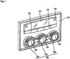
1 ist eine perspektivische Vorderansicht, die eine Bedienkonsole eines Bekleidungsbehandlungsgeräts mit einer Lichtemissionseinrichtung gemäß einer Ausführungsform der Erfindung zeigt; -
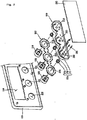
2 ist eine perspektivische Explosionsrückansicht, die die Lichtemissionseinrichtung gemäß der Ausführungsform der Erfindung zeigt; -
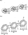
3 ist eine perspektivische Rückansicht, die Kreistasten zeigt, wie sie bei der Lichtemissionseinrichtung gemäß der Ausführungsform der Erfindung angewandt sind; -
4 ist eine perspektivische Vorderansicht, die ein transparentes Fenster zeigt, wie es bei der Lichtemissionseinrichtung gemäß der Ausführungsform der Erfindung angewandt ist; -
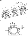
5 ist eine perspektivische Ansicht, die ein Tastenführungselement zeigt, wie es bei der Lichtemissionseinrichtung gemäß der Ausführungsform der Erfindung angewandt ist; -
6 ist eine Vorderansicht, die die gemäß der Ausführungsform der Erfindung angebaute Lichtemissionseinrichtung zeigt; -
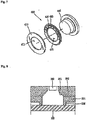
7 ist eine perspektivische Explosionsvorderansicht, die eine Lichtemissionseinrichtung zeigt; -
8 ist eine schematische Schnittansicht, die eine Lichtaufweitungsverhinderungskonstruktion der Lichtemissionseinrichtung zeigt; -
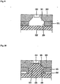
9 ist eine schematische Schnittansicht, die eine Lichtaufweitungsverhinderungskonstruktion der Lichtemissionseinrichtung zeigt; und -
10 ist eine schematische Schnittansicht, die eine Lichtaufweitungsverhinderungskonstruktion der Lichtemissionseinrichtung gemäß einer Ausführungsform der Erfindung zeigt.
-
1 Fig. 15 is a front perspective view showing an operation panel of a clothes treating apparatus having a light emitting device according to an embodiment of the invention; -
2 Fig. 13 is an exploded perspective rear view showing the light emitting device according to the embodiment of the invention; -
3 Fig. 12 is a rear perspective view showing circle buttons applied to the light emitting device according to the embodiment of the invention; -
4 Fig. 12 is a front perspective view showing a transparent window as applied to the light emitting device according to the embodiment of the invention; -
5 Fig. 15 is a perspective view showing a key guide member applied to the light emitting device according to the embodiment of the invention; -
6 Fig. 10 is a front view showing the light emitting device mounted according to the embodiment of the invention; -
7 Fig. 13 is an exploded front perspective view showing a light emitting device; -
8th Fig. 10 is a schematic sectional view showing a light expansion prevention structure of the light emitting device; -
9 Fig. 10 is a schematic sectional view showing a light expansion prevention structure of the light emitting device; and -
10 FIG. 15 is a schematic sectional view showing a light expansion preventing structure of the light emitting device according to an embodiment of the invention. FIG.
DETAILLIERTE BESCHREIBUNG DER ERFINDUNGDETAILED DESCRIPTION OF THE INVENTION
Nachfolgend erfolgt eine detaillierte Beschreibung der bevorzugten Ausführungsformen der Erfindung, zu denen in den beigefügten Zeichnungen Beispiele dargestellt sind.The following is a detailed description of preferred embodiments of the invention, examples of which are illustrated in the accompanying drawings.
Hier ist eine Lichtemissionseinrichtung gemäß der Erfindung offenbart, die bei einer Bedienkonsole eines Bekleidungsbehandlungsgeräts angewandt ist, jedoch kann sie bei anderen Komponenten des Bekleidungsbehandlungsgeräts angewandt sein.Here, there is disclosed a light emitting device according to the invention applied to an operation panel of a clothes treating apparatus, but it can be applied to other components of the clothes treating machine.
Die
Gemäß den
Die Lichtemissionseinrichtung verfügt über Kreistasten
Insbesondere bestehen die Kreistasten aus einer ersten Kreistaste
Die Kreistasten
Die Bedienkonsole
Die mehreren Lichtemissionsbauteilen
Die Lichtemissionsbauteilen
Das transparente Fenster
Jeder der Kreistasten
Das Tastenführungselement
Die Kreistasten
Um den Verbindungsprozess zu erleichtern, bedeckt, nachdem die Kreistasten
Die Lichtemissionsbauteile
Zwischen dem Tastenführungselement
Die
Gemäß der
Jeder Tastenkörper
Jede Halteachse
Die ersten Falschzusammenbauverhinderungsvorsprünge
Wie es in der
Das Tastenführungselement
Die zweiten Falschzusammenbauverhinderungsvorsprünge
Wie es in der
Die oberen Verbindungshaken
Die oberen Verbindungshaken
Außerdem stehen die oberen Verbindungshaken
Die
Gemäß der
Insbesondere sind das erste Tastenfenster
Die integrierten Bauteilabdeckungen
Die Tastendurchdringlöcher
Die ersten Rastvorsprünge
Indessen sind der erste Verbindungsabschnitt
Außerdem kann das transparente Fenster
Die
Gemäß der
Die Lichtemissionslochvorsprungsabschnitte
Die Lichtemissionslöcher
Bei dieser Ausführungsform liegen von den Lichtemissionslochvorsprungsabschnitten
Die Halteachse-Durchdringungslöcher
Die ersten Falschzusammenbauverhinderungslöcher
Außerdem sind die zweiten Falschzusammenbauverhinderungslöcher
Auf Grund dieser Konfiguration können die ersten Falschzusammenbauverhinderungsvorsprünge
Hierbei können die ersten Falschzusammenbauverhinderungsvorsprünge
Die oberen Verbindungshaken
Die Montagelochbildungsvorsprünge
Durch diese Konfiguration ist es möglich, das transparente Fenster
Hierbei können die Montagelochbildungsvorsprünge
Die
Gemäß der
Die
Gemäß der
Der Wählknopf
Das transparente Fenster
Die
Gemäß der
Hierbei stellt die Beschreibung die dritte Führungseinheit
Wie dargestellt, liegen die Trägereinheit
Da die Trägereinheit
Durch diese Konfiguration kann das vom Lichtemissionsbauteil
Außerdem steht der Lichtemissionslochvorsprungsabschnitt
Indessen kann die Trägereinheit
Die
Gemäß der
Durch diese Konfiguration ist es möglich, die Verbindungskonstruktion zwischen der Trägereinheit
Die
Gemäß der
Außerdem ist der zum Lichtemissionsbauteil
Durch eine derartige Konfiguration kann, durch den Vorsprungsabschnitt
Bei der Lichtemissionseinrichtung des Bekleidungsbehandlungsgeräts gemäß einer Ausführungsform der Erfindung kann, durch das mehrere Lichtemissionsbauteil abdeckende transparente Fenster, die Fläche desselben, wie sie jedem Lichtemissionsbauteil zugeordnet ist, vergrößert werden. Demgemäß kann die nach außen gestrahlte Lichtmenge erhöht werden, wodurch es möglich ist, von außen her leicht zu erkennen, ob die Lichtemissionsbauteile Licht emittieren oder nicht.In the light emitting device of the clothes treating apparatus according to an embodiment of the invention, by the transparent window covering a plurality of the light emitting member, the area thereof as assigned to each light emitting member can be increased. Accordingly, the amount of light radiated to the outside can be increased, whereby it is possible to easily recognize from the outside whether the light emitting devices emit light or not.
Ferner ist, bei dieser Lichtemissionseinrichtung für ein Bekleidungsbehandlungsgerät, das transparente Fenster integral ausgebildet, weswegen es möglich ist, für ein hervorragendes Aussehen zu sorgen, die Handhabung des transparenten Fensters zu erleichtern und Zeit und Kosten zu verringern, die beim Verbindungsprozess aufgewandt werden.Further, in this light emitting device for a clothes treating apparatus, the transparent window is integrally formed, and therefore it is possible to provide an excellent appearance, to facilitate the handling of the transparent window, and to reduce the time and cost involved in the joining process.
Ferner sind, bei der Lichtemissionseinrichtung für ein Bekleidungsbehandlungsgerät, das die Tastenführungseinheit bildende Tastenführungselement und das transparente Fenster benachbart zueinander angeordnet, weswegen es möglich ist, die Wechselwirkung zwischen den durch die Lichtemissionslöcher jeder Lichtemissionseinrichtung laufenden Lichtstrahlen zu minimieren. Daher ist, durch integrales Ausbilden des transparenten Fensters, die Fläche desselben, wie sie jedem Lichtemissionsbauteil zugeordnet ist, vergrößert, und demgemäß ist es möglich, die Lichtemissionseffizienz zu erhöhen, was sich daraus ergibt, dass eine Wechselwirkung zwischen den von den jeweiligen Lichtemissionsbauteilen erzeugten Lichtstrahlen verhindert wird, und es kann die nach außen durchgelassene Lichtmenge erhöht werden, und es kann für ein hervorragendes Aussehen gesorgt werden.Further, in the light emitting device for a clothes treating apparatus, the key guiding unit constituting the key guiding unit and the transparent window are adjacent to each other, therefore, it is possible to minimize the interaction between the light beams passing through the light emitting holes of each light emitting means. Therefore, by integrally forming the transparent window, the area thereof as associated with each light emitting device is increased, and accordingly, it is possible to increase the light emitting efficiency, resulting in an interaction between the light beams generated by the respective light emitting devices is prevented, and the amount of light transmitted to the outside can be increased, and excellent appearance can be provided.
Ferner ist es, bei der Lichtemissionseinrichtung für ein Bekleidungsbehandlungsgerät, durch die Falschzusammenbauverhinderungsvorsprünge und die Falschzusammenbauverhinderungslöcher, die benachbart zueinander ausgebildet sind, möglich, einen Fehleinbau der Tasten zu vermeiden, wenn diese jeweils mit dem Tastenführungselement verbunden werden. Demgemäß ist es möglich, Zeit und Kosten zu senken, wie sie bei einem Prozess zum Reparieren eines Fehleinbaus der Tasten aufzuwenden sind, und eine Fehlbedienung des Bekleidungsbehandlungsgeräts zu vermeiden, die sich aus der Auswahl einer falsch eingebauten Taste ergibt.Further, in the light-emitting device for a clothes treating apparatus, by the misinsertion prevention protrusions and the mis-assembly preventing holes formed adjacent to each other, it is possible to avoid mis-installation of the keys when connected to the key-guiding member, respectively. Accordingly, it is possible to reduce the time and cost involved in a process of repairing mis-installation of the keys and to avoid misoperation of the clothes treating apparatus resulting from the selection of a wrongly installed key.
Die vorstehenden Ausführungsformen und Vorteile sind lediglich beispielhaft, und sie sind nicht als die vorliegende Offenbarung beschränkend auszulegen. Die vorliegenden Lehren können leicht bei anderen Vorrichtungstypen angewandt werden. Diese Beschreibung soll veranschaulichend sein und den Schutzumfang der Ansprüche nicht einschränken. Der Fachmann erkennt viele Alternativen, Modifizierungen und Variationen. Die Merkmale, Konstruktionen, Methoden sowie andere Eigenschaften der hier beschriebenen Ausführungsbeispiele können auf verschiedene Arten kombiniert werden, um zusätzliche und/oder alternative Ausführungsbeispiele zu erhalten.The foregoing embodiments and advantages are merely exemplary, and are not to be construed as limiting the present disclosure. The present teachings are readily applicable to other types of devices. This description is intended to be illustrative and not to limit the scope of the claims. The skilled artisan will recognize many alternatives, modifications and variations. The features, constructions, methods and other features of the embodiments described herein may be combined in various ways to obtain additional and / or alternative embodiments.
Claims (7)
Applications Claiming Priority (2)
| Application Number | Priority Date | Filing Date | Title |
|---|---|---|---|
| KR10-2007-0039029 | 2007-04-20 | ||
| KR1020070039029A KR20080094504A (en) | 2007-04-20 | 2007-04-20 | Light emitting device of the clothing processor |
Publications (2)
| Publication Number | Publication Date |
|---|---|
| DE102008019552A1 DE102008019552A1 (en) | 2008-11-13 |
| DE102008019552B4 true DE102008019552B4 (en) | 2018-08-23 |
Family
ID=39829597
Family Applications (1)
| Application Number | Title | Priority Date | Filing Date |
|---|---|---|---|
| DE102008019552.9A Expired - Fee Related DE102008019552B4 (en) | 2007-04-20 | 2008-04-18 | Light emission device for a clothing treatment device |
Country Status (4)
| Country | Link |
|---|---|
| US (1) | US7943876B2 (en) |
| KR (1) | KR20080094504A (en) |
| CN (1) | CN101307558A (en) |
| DE (1) | DE102008019552B4 (en) |
Families Citing this family (9)
| Publication number | Priority date | Publication date | Assignee | Title |
|---|---|---|---|---|
| US9148937B2 (en) | 2008-09-03 | 2015-09-29 | Lutron Electronics Co., Inc. | Radio-frequency lighting control system with occupancy sensing |
| US9277629B2 (en) | 2008-09-03 | 2016-03-01 | Lutron Electronics Co., Inc. | Radio-frequency lighting control system with occupancy sensing |
| US8009042B2 (en) | 2008-09-03 | 2011-08-30 | Lutron Electronics Co., Inc. | Radio-frequency lighting control system with occupancy sensing |
| USRE47511E1 (en) | 2008-09-03 | 2019-07-09 | Lutron Technology Company Llc | Battery-powered occupancy sensor |
| US8228184B2 (en) * | 2008-09-03 | 2012-07-24 | Lutron Electronics Co., Inc. | Battery-powered occupancy sensor |
| US8199010B2 (en) | 2009-02-13 | 2012-06-12 | Lutron Electronics Co., Inc. | Method and apparatus for configuring a wireless sensor |
| JP4830016B2 (en) * | 2009-11-17 | 2011-12-07 | スタンレー電気株式会社 | Vehicle headlamp |
| KR101704046B1 (en) * | 2011-02-28 | 2017-02-07 | 현대자동차주식회사 | Transmission indicator for vehicle |
| PL3187648T3 (en) * | 2015-12-29 | 2022-07-25 | Electrolux Appliances Aktiebolag | Household appliance |
Citations (7)
| Publication number | Priority date | Publication date | Assignee | Title |
|---|---|---|---|---|
| DE2413649B2 (en) * | 1974-03-21 | 1976-02-05 | Licentia Patent-Verwaltungs-Gmbh, 6000 Frankfurt | DISPLAY BOARD WITH OBJECT DISPLAY AND SIGNAL BARS |
| GB2008286A (en) * | 1977-11-16 | 1979-05-31 | Philips Nv | Selection device for a domestic appliance |
| DE10147793C1 (en) * | 2001-09-27 | 2003-02-13 | Miele & Cie | Rotary push-button switch has labyrinth seal defined between inner and outer operating elements for push-button rod and switch rotor shaft |
| DE10144668A1 (en) * | 2001-09-11 | 2003-03-27 | Bsh Bosch Siemens Hausgeraete | Display on e.g. washing and drying machines, includes strip of lights flashing to show rotation, speed and optionally course of program execution |
| DE10309823A1 (en) * | 2003-03-05 | 2004-09-16 | Miele & Cie. Kg | Method for operating washing machine function has push- button in control panel which depresses on to switch plate having light source |
| US20050183471A1 (en) * | 2004-02-25 | 2005-08-25 | Kang Dong W. | Control panel assembly for washing machine |
| DE102006023959A1 (en) * | 2005-05-23 | 2007-01-18 | Lg Electronics Inc. | Operating panel for washing machine or drier, has ribs arranged between transparent projections so that light emitted from each LED is only directed towards corresponding transparent projection |
Family Cites Families (11)
| Publication number | Priority date | Publication date | Assignee | Title |
|---|---|---|---|---|
| JPH0997016A (en) * | 1995-10-02 | 1997-04-08 | Oki Electric Ind Co Ltd | Display device of electronic apparatus |
| US5736965A (en) * | 1996-02-07 | 1998-04-07 | Lutron Electronics Co. Inc. | Compact radio frequency transmitting and receiving antenna and control device employing same |
| JP2004522309A (en) * | 2001-06-22 | 2004-07-22 | エルジー エレクトロニクス インコーポレイティド | Control panel assembly for home appliance and method of manufacturing the same |
| JP3937765B2 (en) * | 2001-07-25 | 2007-06-27 | ティアック株式会社 | Switch device with indicator |
| JP2004073706A (en) | 2002-08-22 | 2004-03-11 | Matsushita Electric Ind Co Ltd | Operation display devices for washing machines, etc. |
| JP2006190597A (en) | 2005-01-07 | 2006-07-20 | Rinnai Corp | Lighting device |
| KR101075225B1 (en) * | 2005-02-02 | 2011-10-19 | 삼성전자주식회사 | Washing machine |
| US7629548B2 (en) * | 2005-07-14 | 2009-12-08 | Access Business Group International Llc | Control panel assembly |
| US7222979B1 (en) * | 2005-11-09 | 2007-05-29 | Cfm Corporation | Illuminated dial |
| US7670039B2 (en) * | 2006-03-17 | 2010-03-02 | Lutron Electronics Co., Inc. | Status indicator lens and light pipe structure for a dimmer switch |
| US7554463B2 (en) * | 2006-04-18 | 2009-06-30 | Whirlpool Corporation | Appliance information communication system |
-
2007
- 2007-04-20 KR KR1020070039029A patent/KR20080094504A/en not_active Ceased
-
2008
- 2008-04-17 US US12/104,867 patent/US7943876B2/en not_active Expired - Fee Related
- 2008-04-18 DE DE102008019552.9A patent/DE102008019552B4/en not_active Expired - Fee Related
- 2008-04-18 CN CNA2008101428675A patent/CN101307558A/en active Pending
Patent Citations (7)
| Publication number | Priority date | Publication date | Assignee | Title |
|---|---|---|---|---|
| DE2413649B2 (en) * | 1974-03-21 | 1976-02-05 | Licentia Patent-Verwaltungs-Gmbh, 6000 Frankfurt | DISPLAY BOARD WITH OBJECT DISPLAY AND SIGNAL BARS |
| GB2008286A (en) * | 1977-11-16 | 1979-05-31 | Philips Nv | Selection device for a domestic appliance |
| DE10144668A1 (en) * | 2001-09-11 | 2003-03-27 | Bsh Bosch Siemens Hausgeraete | Display on e.g. washing and drying machines, includes strip of lights flashing to show rotation, speed and optionally course of program execution |
| DE10147793C1 (en) * | 2001-09-27 | 2003-02-13 | Miele & Cie | Rotary push-button switch has labyrinth seal defined between inner and outer operating elements for push-button rod and switch rotor shaft |
| DE10309823A1 (en) * | 2003-03-05 | 2004-09-16 | Miele & Cie. Kg | Method for operating washing machine function has push- button in control panel which depresses on to switch plate having light source |
| US20050183471A1 (en) * | 2004-02-25 | 2005-08-25 | Kang Dong W. | Control panel assembly for washing machine |
| DE102006023959A1 (en) * | 2005-05-23 | 2007-01-18 | Lg Electronics Inc. | Operating panel for washing machine or drier, has ribs arranged between transparent projections so that light emitted from each LED is only directed towards corresponding transparent projection |
Also Published As
| Publication number | Publication date |
|---|---|
| KR20080094504A (en) | 2008-10-23 |
| CN101307558A (en) | 2008-11-19 |
| US7943876B2 (en) | 2011-05-17 |
| DE102008019552A1 (en) | 2008-11-13 |
| US20080259591A1 (en) | 2008-10-23 |
Similar Documents
| Publication | Publication Date | Title |
|---|---|---|
| DE102008019552B4 (en) | Light emission device for a clothing treatment device | |
| DE102008019555A1 (en) | Selection element attachment for a clothing treatment device and associated cultivation method | |
| DE202020000279U1 (en) | Switch device comprising electrical device device | |
| DE112006002707B4 (en) | Washing machine | |
| EP2979288A1 (en) | Key module for a keyboard key and method for producing a key module for a keyboard key | |
| DE69321521T2 (en) | Light guide with high permeability at a short distance from a function key | |
| DE202013012867U1 (en) | Control panel layout | |
| DE102016220768A1 (en) | Cover for air conditioning and air distribution box for air conditioning | |
| DE102007042069A1 (en) | Control panel arrangement for a laundry machine | |
| DE102006023959A1 (en) | Operating panel for washing machine or drier, has ribs arranged between transparent projections so that light emitted from each LED is only directed towards corresponding transparent projection | |
| DE202017100859U1 (en) | keyboard | |
| DE102004025878B4 (en) | Touch-sensitive pushbutton | |
| DE102010063014A1 (en) | Control panel for use in household appliance e.g. washing machine, has cover-base body comprising switching device that is fixed to conducting surface of cap, where cap is attached to base body in detachable manner by welding or gluing | |
| DE102006012201B4 (en) | Tumble dryer with control panel | |
| DE19740705B4 (en) | Kit for a control panel for household appliances with cabinet-shaped housing | |
| DE112021006136T5 (en) | DISPLAY DEVICE AND INPUT DEVICE | |
| DE102010033390B4 (en) | Capacitive touch and / or proximity switch | |
| DE10158629B4 (en) | switch | |
| DE112005001538B4 (en) | Control panel arrangement of a washing machine | |
| DE102006023954B4 (en) | Control panel for laundry processing machine | |
| DE19737524A1 (en) | Domestic white goods unit, e.g. refrigerator, freezer, washing machine | |
| DE102016218807A1 (en) | household appliance | |
| DE102009010739B4 (en) | Button arrangement and washing machine with this | |
| DE102008019553B4 (en) | Device for mounting a display window and buttons for a clothing treatment device | |
| EP1545177A1 (en) | Centering frame |
Legal Events
| Date | Code | Title | Description |
|---|---|---|---|
| OP8 | Request for examination as to paragraph 44 patent law | ||
| R016 | Response to examination communication | ||
| R016 | Response to examination communication | ||
| R018 | Grant decision by examination section/examining division | ||
| R020 | Patent grant now final | ||
| R119 | Application deemed withdrawn, or ip right lapsed, due to non-payment of renewal fee |