DE102007018564B4 - Method and device for deploying a membrane in space - Google Patents
Method and device for deploying a membrane in space Download PDFInfo
- Publication number
- DE102007018564B4 DE102007018564B4 DE102007018564A DE102007018564A DE102007018564B4 DE 102007018564 B4 DE102007018564 B4 DE 102007018564B4 DE 102007018564 A DE102007018564 A DE 102007018564A DE 102007018564 A DE102007018564 A DE 102007018564A DE 102007018564 B4 DE102007018564 B4 DE 102007018564B4
- Authority
- DE
- Germany
- Prior art keywords
- membrane
- frame
- mast
- bending
- masts
- Prior art date
- Legal status (The legal status is an assumption and is not a legal conclusion. Google has not performed a legal analysis and makes no representation as to the accuracy of the status listed.)
- Expired - Fee Related
Links
Images


Classifications
-
- B—PERFORMING OPERATIONS; TRANSPORTING
- B64—AIRCRAFT; AVIATION; COSMONAUTICS
- B64G—COSMONAUTICS; VEHICLES OR EQUIPMENT THEREFOR
- B64G1/00—Cosmonautic vehicles
- B64G1/22—Parts of, or equipment specially adapted for fitting in or to, cosmonautic vehicles
- B64G1/40—Arrangements or adaptations of propulsion systems
- B64G1/407—Solar sailing
-
- B—PERFORMING OPERATIONS; TRANSPORTING
- B64—AIRCRAFT; AVIATION; COSMONAUTICS
- B64G—COSMONAUTICS; VEHICLES OR EQUIPMENT THEREFOR
- B64G1/00—Cosmonautic vehicles
- B64G1/22—Parts of, or equipment specially adapted for fitting in or to, cosmonautic vehicles
- B64G1/222—Parts of, or equipment specially adapted for fitting in or to, cosmonautic vehicles for deploying structures between a stowed and deployed state
- B64G1/2221—Parts of, or equipment specially adapted for fitting in or to, cosmonautic vehicles for deploying structures between a stowed and deployed state characterised by the manner of deployment
- B64G1/2222—Folding
-
- B—PERFORMING OPERATIONS; TRANSPORTING
- B64—AIRCRAFT; AVIATION; COSMONAUTICS
- B64G—COSMONAUTICS; VEHICLES OR EQUIPMENT THEREFOR
- B64G1/00—Cosmonautic vehicles
- B64G1/22—Parts of, or equipment specially adapted for fitting in or to, cosmonautic vehicles
- B64G1/222—Parts of, or equipment specially adapted for fitting in or to, cosmonautic vehicles for deploying structures between a stowed and deployed state
- B64G1/2229—Parts of, or equipment specially adapted for fitting in or to, cosmonautic vehicles for deploying structures between a stowed and deployed state characterised by the deployment actuating mechanism
-
- B—PERFORMING OPERATIONS; TRANSPORTING
- B64—AIRCRAFT; AVIATION; COSMONAUTICS
- B64G—COSMONAUTICS; VEHICLES OR EQUIPMENT THEREFOR
- B64G1/00—Cosmonautic vehicles
- B64G1/22—Parts of, or equipment specially adapted for fitting in or to, cosmonautic vehicles
- B64G1/42—Arrangements or adaptations of power supply systems
- B64G1/44—Arrangements or adaptations of power supply systems using radiation, e.g. deployable solar arrays
-
- B—PERFORMING OPERATIONS; TRANSPORTING
- B64—AIRCRAFT; AVIATION; COSMONAUTICS
- B64G—COSMONAUTICS; VEHICLES OR EQUIPMENT THEREFOR
- B64G1/00—Cosmonautic vehicles
- B64G1/22—Parts of, or equipment specially adapted for fitting in or to, cosmonautic vehicles
- B64G1/46—Arrangements or adaptations of devices for control of environment or living conditions
- B64G1/50—Arrangements or adaptations of devices for control of environment or living conditions for temperature control
-
- B—PERFORMING OPERATIONS; TRANSPORTING
- B64—AIRCRAFT; AVIATION; COSMONAUTICS
- B64G—COSMONAUTICS; VEHICLES OR EQUIPMENT THEREFOR
- B64G1/00—Cosmonautic vehicles
- B64G1/22—Parts of, or equipment specially adapted for fitting in or to, cosmonautic vehicles
- B64G1/66—Arrangements or adaptations of apparatus or instruments, not otherwise provided for
Landscapes
- Engineering & Computer Science (AREA)
- Remote Sensing (AREA)
- Aviation & Aerospace Engineering (AREA)
- Life Sciences & Earth Sciences (AREA)
- Sustainable Development (AREA)
- Sustainable Energy (AREA)
- Chemical & Material Sciences (AREA)
- Combustion & Propulsion (AREA)
- Health & Medical Sciences (AREA)
- Biodiversity & Conservation Biology (AREA)
- Environmental & Geological Engineering (AREA)
- Environmental Sciences (AREA)
- General Health & Medical Sciences (AREA)
- Toxicology (AREA)
- Aerials With Secondary Devices (AREA)
Abstract
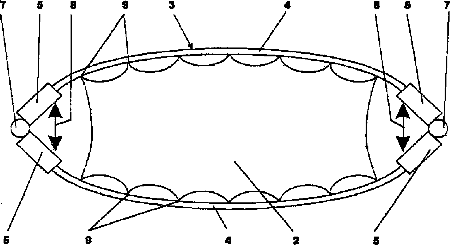
Zum Entfalten einer Membran (2) im Weltraum, wobei die Membran (2) randseitig an einen Rahmen (3) angebunden ist, wird eine von dem Rahmen (3) umschlossene Fläche durch zumindest teilweilweise elastisches Biegen mindestens eines Mastes (4), der Teil des Rahmens (3) ist, vergrößert, bis die Membran (2) innerhalb des Rahmens (3) entfaltet ist.For unfolding a membrane (2) in outer space, wherein the membrane (2) is connected to the edge of a frame (3), a surface enclosed by the frame (3) becomes at least partially elastically bending at least one mast (4), the part of the frame (3) is enlarged until the membrane (2) is deployed inside the frame (3).
Description
TECHNISCHES GEBIET DER ERFINDUNGTECHNICAL FIELD OF THE INVENTION
Die Erfindung bezieht sich auf ein Verfahren zum Entfalten einer Membran im Weltraum mit den Merkmalen des Oberbegriffs des unabhängigen Patentanspruchs 1 sowie auf eine Vorrichtung zum Entfalten einer Membran im Weltraum mit den Merkmalen des Oberbegriffs des unabhängigen Patentanspruchs 9.The invention relates to a method for deploying a membrane in space having the features of the preamble of
Unter einer Membran sind hier insbesondere folgende Strukturen zu verstehen; dennoch ist der Begriff der Membran nicht auf diese zweidimensionalen Strukturen beschränkt sondern umfasst auch andere im Wesentlichen zweidimensionale Strukturen von insbesondere großflächiger Ausdehnung:
- – Membranantennen, z. B. in C-Band, L-Band, P-Band für Fernerkundungsmissionen (GMES);
- – Sonnensegel für treibstofflose Antriebe;
- – Ausleger mit flexiblen Solarzellen;
- – Reflektoren;
- – Luftbremsen für passives Deorbiting zur Vermeidung von Weltraummüll;
- – Sonnenschilde für Kühlungszwecke;
- – Solaröfen zu Erwärmungszwecken.
- - Membrane antennas, z. In C-band, L-band, P-band for remote sensing missions (GMES);
- - Awning for fuel-free drives;
- - Booms with flexible solar cells;
- - reflectors;
- - air brakes for passive deorbiting to avoid space debris;
- - Sunshades for cooling purposes;
- - Solar ovens for heating purposes.
STAND DER TECHNIKSTATE OF THE ART
Große, extrem leichte, entfaltbare Membranen spielen für eine Reihe gegenwärtiger und zukünftiger Raumfahrtanwendungen eine wichtige Rolle, z. B. als Reflektoren, Sonnensegel, Solarzellenausleger und Membranantennen. Innovative Konzepte für derartige Anwendungen basieren häufig auf sehr dünnen Membranen, die über entfaltbare Rahmen oder Stützen im Weltraum aufgespannt werden müssen. Dabei ist für die verlässliche Funktion, z. B. von Membranantennen, die exakte und faltenfreie Ausrichtung der jeweiligen Membran sehr wichtig. Aus diesem Grund müssen Entfaltungs- und Aufspannverfahren und -vorrichtungen bereitgestellt werden, die sowohl das sichere Entfalten der Membran gewährleisten, als auch im Betrieb eine exakte und faltenfreie Positionierung erlauben. Die Größe zukünftiger Membransysteme wird von einigen 10 bis zu mehreren 100 m eingeschätzt, was einer Membranfläche von einigen 100 bis zu mehreren 10.000 qm entspricht.Large, extremely lightweight, deployable membranes play an important role in a range of current and future space applications, such as: As reflectors, awnings, solar cell boom and membrane antennas. Innovative concepts for such applications are often based on very thin membranes that need to be deployed over deployable frames or pillars in space. It is for the reliable function, eg. B. of membrane antennas, the exact and wrinkle-free orientation of the respective membrane very important. For this reason, deployment and clamping methods and devices must be provided which ensure both safe deployment of the membrane and allow accurate and wrinkle-free positioning during operation. The size of future membrane systems is estimated to be from several tens to several hundreds of meters, which corresponds to a membrane area of several 100 to several 10,000 square meters.
Ein Verfahren und eine Vorrichtung zum Entfalten von Membranen im Weltraum sind aus der
Als Vorrichtung mit dem Merkmal des unabhängigen Patentanspruchs 9 ist ein L-Band Antennendemonstrator der Firma ILC Dover mit aufblasbarem Rahmen bekannt. Durch das Aufblasen des Rahmens nimmt dieser seine vorgesehene ebene Form ein, in der er dann im Weltraum aushärten kann, um auch nach einem Verlust des Drucks in seinem inneren die vorgegebene Form beizubehalten. Vorteil ist dabei, dass die in dem Rahmen angeordnete Membranantenne an vielen Punkten randseitig an dem Rahmen befestigt ist und dadurch eine gleichmäßigere Spannungsverteilung aufweist. Allerdings ist die geometrische Konturtreue beim Aushärten des Rahmens im Weltraum relativ gering, da während der Aushärtung kein formgebendes Werkzeug zur Verfügung steht. Inhomogenitäten während der Aushärtung des Rahmens und der damit verbundene geometrische Verzug übertragen sich auf die Membran. Das mit der Aushärtung im Weltraum verbundene Risiko ist folglich sehr hoch. insbesondere bei Anwendungen, die eine hohe Konturtreue verlangen, wie dies bei Membranantennen der Fall ist.As an apparatus having the feature of
Neben dem voranstehend beschriebenen L-Band Antennendemonstrator der Firma ILC Dover, bei dem der ganze Rahmen aus durch Aufblasen entfaltbaren Masten besteht, die ein gemeinsames Innenvolumen einschließen, ist als weitere Vorrichtung mit den Merkmalen des Oberbegriffs des unabhängigen Patentanspruchs 9 eine SAR Antenne der Firma L'Garde mit zwei parallel zueinander angeordneten aufblasbaren Masten bekannt, die parallel zueinander angeordnete starre Rahmenabschnitte auseinander bewegen, um eine Membranantenne zu entfalten. Hier ist die Membranantenne jedoch wieder nur punktuell randseitig angehängt, was mit den bereits voranstehend beschriebenen Nachteilen verbunden ist.In addition to the above-described L-band antenna demonstrator company ILC Dover, in which the whole frame consists of inflatable deployable masts, which include a common internal volume, is a further device having the features of the preamble of
Es ist auch in Betracht gezogen worden, Membranen im Weltraum durch Einsatz von Pantograph-artigen Systemen zu entfalten. Der konstruktive Aufwand und das Gewicht solcher Systeme sind jedoch groß, wenn die jeweilige Membran mit dichten randseitigen Anbindungspunkten an einen allseitig geschlossenen Rahmen angebunden sein soll, um sie über ihre gesamte Fläche geometrisch genau zu entfalten.It has also been considered to develop membranes in space by using pantograph-like systems. However, the design effort and the weight of such systems are great when the respective membrane with Close peripheral attachment points should be connected to a frame closed on all sides in order to develop them geometrically accurate over their entire surface.
Aus der
Aus der
Aus der
AUFGABE DER ERFINDUNGOBJECT OF THE INVENTION
Der Erfindung liegt die Aufgabe zugrunde, ein Verfahren und eine Vorrichtung zum Entfalten einer Membran im Weltraum aufzuzeigen, die es mit vergleichsweise geringem Aufwand erlauben, eine homogene Spannungsverteilung über der Membran einzustellen, um insbesondere ungewollte Knittermuster und andere nicht homogen gespannte Bereiche zu vermeiden.The invention has for its object to provide a method and apparatus for deploying a membrane in space, which allow it with relatively little effort to set a homogeneous stress distribution over the membrane to avoid unwanted creases and other non-homogeneous areas in particular tense.
LÖSUNGSOLUTION
Erfindungsgemäß wir diese Aufgabe durch ein Verfahren mit den Merkmalen des unabhängigen Patentanspruchs 1 und eine Vorrichtung mit den Merkmalen des unabhängigen Patentanspruchs 9 gelöst. Bevorzugte Ausführungsformen des Verfahrens sind in den abhängigen Patentansprüchen 2 bis 8, bevorzugte Ausführungsformen der Vorrichtung in den abhängigen Patentansprüchen 10 bis 16 beschrieben.According to the invention we have achieved this object by a method having the features of
BESCHREIBUNG DER ERFINDUNGDESCRIPTION OF THE INVENTION
Bei dem neuen Verfahren wird der mindestens eine Mast, der Teil des Rahmens ist, zum Vergrößern der von dem Rahmen umschlossenen Fläche gebogen. Diese Deformation erfolgt dabei zumindest teilweise elastisch. Der Mast kann auch zu einem Teil plastisch verformt werden. In jedem Fall ist aber ein wesentlicher Anteil der Verformung elastisch. Die Biegeverformung des Mastes wird dabei nicht nur durch die Elastizität des Mastes selbst sondern auch durch die von der entfalteten Membran bereitgestellten Gegenkräfte abgestützt, so dass ein Einknicken des Mastes in Folge einer überhöhten Durchbiegung durch eine adäquate Ausbildung der Deformationseigenschaften des Mastes leicht zu vermeiden ist. Die gewünschte Formstabilität der entfalteten Membran stellt sich bei dem neuen Verfahren dadurch ein, dass sich ein Kräftegleichgewicht zwischen den Biegemomenten auf den Mast bzw. den daraus resultierenden Kräften einerseits und den elastischen Rückstellkräften des Masts und der Spannung der Membran andererseits einstellt. So kann durch Variation des beim Biegen auf den Mast aufgebrachten Biegemoments eine vorgegebene Spannungsverteilung über der Membran eingestellt werden. Zumindest kann überall eine gewisse Mindestspannung der Membran erreicht werden. Bei adäquater Abstimmung der Membran auf den Rahmen ist die Spannungsverteilung auch weitgehend homogen und durch Erhöhung des Biegemoments wird die im Wesentlichen homogene Spannung der Membran ohne Änderung dieser Homogenität erhöht. Durch Variation des beim Biegen auf den Mast aufgebrachten Biegemoments kann auch eine vorgegebene Oberflächenqualität der Membran aktiv kontrolliert werden, wobei es nicht direkt auf eine homogene Spannungsverteilung über die Membran ankommt, solange diese z. B. glatt, d. h. knitterfrei bleibt. So neigen Membranstrukturen zum Beispiel dazu, unter Temperatureinflüssen Knittermuster auszubilden. Durch das neue Verfahren besteht die Möglichkeit, die Spannungsverteilung der Membran auch während des Betriebs im Weltraum unter unterschiedlichen Umgebungsbedingungen zu korrigieren. Das Biegen des Masts hat bei dem neuen Verfahren demnach häufig eine doppelte Funktion, nämlich einerseits das eigentliche Entfalten der Membran und andererseits die anschließende die anschließende aktive Kontrolle einer gewünschten Spannungsverteilung über der Membran bzw. einer gewünschten Oberflächenqualität der Membran während ihres Betriebs. Die aktive Flächenkontrolle ist insbesondere bei Antennenentwicklungen wichtig.In the new method, the at least one mast, which is part of the frame, is bent to increase the area enclosed by the frame. This deformation takes place at least partially elastic. The mast can also be plastically deformed to a part. In any case, however, a significant proportion of the deformation is elastic. The bending deformation of the mast is supported not only by the elasticity of the mast itself but also by the counter-forces provided by the unfolded membrane, so that buckling of the mast as a result of excessive deflection by an adequate design of the deformation properties of the mast is easy to avoid. The desired dimensional stability of the unfolded membrane adjusts itself in the new method that an equilibrium of forces between the bending moments on the mast and the resulting forces on the one hand and the elastic restoring forces of the mast and the tension of the membrane on the other hand sets. Thus, by varying the bending moment applied to the mast during bending, a predetermined stress distribution over the membrane can be set. At least anywhere a certain minimum voltage of the membrane can be achieved. If the membrane is adequately matched to the frame, the stress distribution is also largely homogeneous and increasing the bending moment increases the substantially homogeneous tension of the membrane without changing this homogeneity. By varying the bending moment applied to the mast during bending, it is also possible to actively control a given surface quality of the membrane, whereby it does not depend directly on a homogeneous distribution of stress across the membrane, as long as these z. B. smooth, ie remains wrinkle-free. For example, membrane structures tend to form creases under the influence of temperature. The new method makes it possible to correct the stress distribution of the membrane during operation in space under different environmental conditions. The bending of the mast has therefore often a double function in the new method, namely on the one hand, the actual unfolding of the membrane and on the other hand, the subsequent subsequent active control of a desired stress distribution across the membrane or a desired surface quality of the membrane during its operation. Active area control is particularly important in antenna developments.
Es gibt verschiedene Möglichkeiten, den Mast zur Vergrößerung der von dem Rahmen umschlossenen Fläche zu biegen. So kann mindestens eines seiner Enden eingebogen werden. Es können auch beide Enden gleichzeitig gegeneinander eingebogen werden. Dies kann aktiv geschehen oder auch passiv, indem die Enden des Masts wie beim Spannen eines Bogens aufeinander zu bewegt werden.There are several ways to bend the mast to increase the area enclosed by the frame. So at least one of its ends can be inflected. It is also possible for both ends to be simultaneously bent against each other. This can be done actively or passively by moving the ends of the mast towards each other as in tensioning a bow.
Besonders bevorzugt ist es bei dem neuen Verfahren, wenn der Mast vor dem Biegen selbst erst entfaltet wird. Dabei ist die Art und Weise, wie der Mast entfaltet wird, nicht entscheidend. Vielmehr kann dies auf sehr unterschiedliche Weise erfolgen, beispielsweise durch Entfalten eines am Boden ausgehärteten zusammengedrückten und aufgerollten Masts entsprechend der
Vorzugsweise werden bei dem neuen Verfahren mehrere Masten zum Vergrößern der von dem Rahmen umschlossenen Fläche zumindest teilweise elastisch gebogen. Beispielsweise können zwei zunächst parallel zueinander angeordnete Masten voneinander weg auseinandergebogen werden. Der Rahmen kann auch eine noch mehrgliedrigere Kette von Masten längs seines Umfangs aufweisen. Vorzugsweise sind die einzelnen Masten dabei in zueinander symmetrischen Randbereichen der Membran angeordnet und werden entsprechend symmetrisch zueinander gebogen. Es versteht sich, dass dabei auch die Membran eine entsprechende Symmetrie aufweist.Preferably, in the new method, a plurality of masts are bent at least partially elastically to increase the area enclosed by the frame. For example, two masts initially arranged parallel to one another can be bent apart from one another. The frame may also have a more multi-link chain of masts along its circumference. Preferably, the individual masts are arranged in mutually symmetrical edge regions of the membrane and are bent correspondingly symmetrical to each other. It is understood that while the membrane has a corresponding symmetry.
Die neue Vorrichtung zum Entfalten einer Membran im Weltraum weist eine Einrichtung auf, die den Mast zum Vergrößern der von dem Rahmen umschlossenen Fläche zumindest teilweise elastisch biegt. Das Biegen erfolgt mit Hilfe mindestens eines Biegeaktuators. Dieser kann dazu vorgesehen sein, ein Ende des Mastes einzubiegen. Zu diesem Zweck kann er einen Zugaktuator aufweisen, mit dem die Enden des Mastes aufeinander zu bewegbar sind.The new device for deploying a membrane in space has means that at least partially elastically flexes the mast to increase the area enclosed by the frame. The bending takes place with the help of at least one bending actuator. This can be intended to insert one end of the mast. For this purpose, it may have a Zugaktuator with which the ends of the mast are movable towards each other.
Eine Entfaltungseinrichtung kann zum Entfalten des Mastes vor dem Biegen vorgesehen sein. Dabei kann zusätzlich eine Aushärteeinrichtung zum Aushärten des Mastes nach dem Entfalten und vor dem Biegen vorgesehen sein. Ein Aushärten des Mastes zu diesem Zeitpunkt kann aber auch bei entsprechender Zusammensetzung des Mastes durch äußere Einflüsse, wie beispielsweise Licht, automatisch erfolgen.An unfolding device may be provided for unfolding the mast prior to bending. In addition, a curing device may be provided for curing the mast after unfolding and before bending. A curing of the mast at this time can also be done automatically with appropriate composition of the mast by external influences, such as light.
Weitere bevorzugte Ausführungsformen der neuen Vorrichtung entsprechen den bereits beschriebenen bevorzugten Ausführungsformen des neuen Verfahrens.Further preferred embodiments of the new device correspond to the already described preferred embodiments of the new method.
Vorteilhafte Weiterbildungen der Erfindung ergeben sich aus den Patentansprüchen, der Beschreibung und den Zeichnungen.Advantageous developments of the invention will become apparent from the claims, the description and the drawings.
KURZBESCHREIBUNG DER FIGURENBRIEF DESCRIPTION OF THE FIGURES
Die Erfindung wird im Folgenden anhand von bevorzugten Ausführungsbeispielen unter Bezugnahme auf die beigefügten Zeichnungen näher erläutert und beschrieben.The invention is explained in more detail below with reference to preferred embodiments with reference to the accompanying drawings and described.
FIGURENBESCHREIBUNGDESCRIPTION OF THE FIGURES
Mit Hilfe von Biegeaktuatoren
Die in verschiedenen Stellungen in den
In
Die folgende
Auch die in
Die vorliegende Erfindung ist jedoch nicht auf zweidimensionale Rahmen
BezugszeichenlisteLIST OF REFERENCE NUMBERS
- 11
- Vorrichtungcontraption
- 22
- Membranmembrane
- 33
- Rahmenframe
- 44
- Mastmast
- 55
- Entfaltungsmoduldeployment module
- 66
- Zugseilrope
- 77
- Gelenkjoint
- 88th
- Biegeaktuatorbending actuator
- 99
- Anbindungspunktaccess point
- 1010
- Gehäusecasing
Claims (16)
Priority Applications (1)
| Application Number | Priority Date | Filing Date | Title |
|---|---|---|---|
| DE102007018564A DE102007018564B4 (en) | 2007-04-18 | 2007-04-18 | Method and device for deploying a membrane in space |
Applications Claiming Priority (1)
| Application Number | Priority Date | Filing Date | Title |
|---|---|---|---|
| DE102007018564A DE102007018564B4 (en) | 2007-04-18 | 2007-04-18 | Method and device for deploying a membrane in space |
Publications (2)
| Publication Number | Publication Date |
|---|---|
| DE102007018564A1 DE102007018564A1 (en) | 2008-10-30 |
| DE102007018564B4 true DE102007018564B4 (en) | 2012-07-26 |
Family
ID=39777337
Family Applications (1)
| Application Number | Title | Priority Date | Filing Date |
|---|---|---|---|
| DE102007018564A Expired - Fee Related DE102007018564B4 (en) | 2007-04-18 | 2007-04-18 | Method and device for deploying a membrane in space |
Country Status (1)
| Country | Link |
|---|---|
| DE (1) | DE102007018564B4 (en) |
Families Citing this family (2)
| Publication number | Priority date | Publication date | Assignee | Title |
|---|---|---|---|---|
| WO2012092933A1 (en) * | 2011-01-07 | 2012-07-12 | Aalborg Universitet | Self-deployable deorbiting space structure |
| DE202014005246U1 (en) | 2014-06-30 | 2015-07-08 | Werner Schaffert | Clamping device for sun sails |
Citations (4)
| Publication number | Priority date | Publication date | Assignee | Title |
|---|---|---|---|---|
| DE1531559A1 (en) * | 1966-10-31 | 1971-04-29 | Hughes Aircraft Co | Foldable frame |
| DE2144034A1 (en) * | 1971-08-30 | 1973-03-08 | Hening W Dipl Ing Scheel | SPACE-SAVING STORAGE OF CIRCULAR AREAS |
| US5515067A (en) * | 1992-03-24 | 1996-05-07 | Agence Spatiale Europenne | Self-supporting shell for use in space |
| DE10109529B4 (en) * | 2001-02-28 | 2005-10-27 | Deutsches Zentrum für Luft- und Raumfahrt e.V. | Device with a flat compressed in cross-section and rolled up length mast |
-
2007
- 2007-04-18 DE DE102007018564A patent/DE102007018564B4/en not_active Expired - Fee Related
Patent Citations (4)
| Publication number | Priority date | Publication date | Assignee | Title |
|---|---|---|---|---|
| DE1531559A1 (en) * | 1966-10-31 | 1971-04-29 | Hughes Aircraft Co | Foldable frame |
| DE2144034A1 (en) * | 1971-08-30 | 1973-03-08 | Hening W Dipl Ing Scheel | SPACE-SAVING STORAGE OF CIRCULAR AREAS |
| US5515067A (en) * | 1992-03-24 | 1996-05-07 | Agence Spatiale Europenne | Self-supporting shell for use in space |
| DE10109529B4 (en) * | 2001-02-28 | 2005-10-27 | Deutsches Zentrum für Luft- und Raumfahrt e.V. | Device with a flat compressed in cross-section and rolled up length mast |
Also Published As
| Publication number | Publication date |
|---|---|
| DE102007018564A1 (en) | 2008-10-30 |
Similar Documents
| Publication | Publication Date | Title |
|---|---|---|
| DE69831695T2 (en) | Deployable precision cantilever arm assembly | |
| DE69428773T2 (en) | Self-expanding spiral structure | |
| DE10048846C1 (en) | Roll-out solar generator for rolling out solar cell structure has roll-out support structure with first transverse support connecting to storage casing for solar cell structure. | |
| DE2110157A1 (en) | Collapsible latticework structure | |
| DE102017101180B4 (en) | Method of packing a spacecraft membrane, spacecraft membrane pack and spacecraft membrane handling unit | |
| DE10109529A1 (en) | Device with a mast compressed flat in cross-section and rolled up lengthways | |
| DE3621430C2 (en) | ||
| DE69206704T2 (en) | Shade sail | |
| DE102011121207A1 (en) | Deformable, developable, changeable and/or multifunctional scissors structures e.g. ladders, manufacturing method for military purpose, involves directly or indirectly providing guides with passively and/or actively activatable drive | |
| DE10043249C2 (en) | Extendable support structure made of deformable tubular elements | |
| DE102007018564B4 (en) | Method and device for deploying a membrane in space | |
| DE102018112690B4 (en) | Device for unfolding a rolled-up elongate hollow body | |
| WO2001016926A1 (en) | Enveloping body | |
| DE102016002372A1 (en) | Method for assembling a tubular tower segment | |
| CH704634B1 (en) | A pneumatic structural component. | |
| DE102010048054A1 (en) | Device for fixing folded sheet, comprises rotated coil body and folded sheet which is wound on coil body, where one end of folded sheet is connected with coil body by mounting device in detached manner | |
| DE102019109810A1 (en) | Apparatus and method for unfolding a rolled up elongated hollow body | |
| DE10241618B4 (en) | Method for stowing and unfolding large-area films | |
| DE2918706A1 (en) | INFLATABLE CONSTRUCTION OF A STRUCTURE OF A FLIGHT DEVICE | |
| EP1593597B1 (en) | Deployable or extendible structure with flexible longerons and supporting elements | |
| DE102017101178B4 (en) | A method of packaging a spacecraft membrane, spacecraft membrane package, and spacecraft membrane handling unit | |
| DE4126933C1 (en) | Spring-joined frame for warning triangle - forms three-side pyramid with four struts and two cords | |
| CH685080A5 (en) | Inflatable antenna reflector | |
| EP1606478A1 (en) | Bow-like support consisting of a pneumatic structural element | |
| DE102023116571B3 (en) | Device for attaching mobile inspection means to inspection objects, arrangement comprising such a device and use of such a device in the inspection of aircraft engines or parts thereof |
Legal Events
| Date | Code | Title | Description |
|---|---|---|---|
| OP8 | Request for examination as to paragraph 44 patent law | ||
| R016 | Response to examination communication | ||
| R018 | Grant decision by examination section/examining division | ||
| R020 | Patent grant now final |
Effective date: 20121027 |
|
| R119 | Application deemed withdrawn, or ip right lapsed, due to non-payment of renewal fee |