DE102007001508B4 - Sliding mechanism for an IS machine - Google Patents
Sliding mechanism for an IS machine Download PDFInfo
- Publication number
- DE102007001508B4 DE102007001508B4 DE102007001508A DE102007001508A DE102007001508B4 DE 102007001508 B4 DE102007001508 B4 DE 102007001508B4 DE 102007001508 A DE102007001508 A DE 102007001508A DE 102007001508 A DE102007001508 A DE 102007001508A DE 102007001508 B4 DE102007001508 B4 DE 102007001508B4
- Authority
- DE
- Germany
- Prior art keywords
- sliding
- axis
- sliding finger
- upper housing
- drive wheel
- Prior art date
- Legal status (The legal status is an assumption and is not a legal conclusion. Google has not performed a legal analysis and makes no representation as to the accuracy of the status listed.)
- Expired - Fee Related
Links
Images

Classifications
-
- C—CHEMISTRY; METALLURGY
- C03—GLASS; MINERAL OR SLAG WOOL
- C03B—MANUFACTURE, SHAPING, OR SUPPLEMENTARY PROCESSES
- C03B9/00—Blowing glass; Production of hollow glass articles
- C03B9/30—Details of blowing glass; Use of materials for the moulds
- C03B9/44—Means for discharging combined with glass-blowing machines, e.g. take-outs
- C03B9/453—Means for pushing newly formed glass articles onto a conveyor, e.g. sweep-out mechanisms; Dead-plate mechanisms
-
- B—PERFORMING OPERATIONS; TRANSPORTING
- B65—CONVEYING; PACKING; STORING; HANDLING THIN OR FILAMENTARY MATERIAL
- B65G—TRANSPORT OR STORAGE DEVICES, e.g. CONVEYORS FOR LOADING OR TIPPING, SHOP CONVEYOR SYSTEMS OR PNEUMATIC TUBE CONVEYORS
- B65G29/00—Rotary conveyors, e.g. rotating discs, arms, star-wheels or cones
-
- C—CHEMISTRY; METALLURGY
- C03—GLASS; MINERAL OR SLAG WOOL
- C03B—MANUFACTURE, SHAPING, OR SUPPLEMENTARY PROCESSES
- C03B35/00—Transporting of glass products during their manufacture, e.g. hot glass lenses, prisms
- C03B35/04—Transporting of hot hollow or semi-hollow glass products
- C03B35/06—Feeding of hot hollow glass products into annealing or heating kilns
- C03B35/08—Feeding of hot hollow glass products into annealing or heating kilns using rotary means directly acting on the products
-
- B—PERFORMING OPERATIONS; TRANSPORTING
- B65—CONVEYING; PACKING; STORING; HANDLING THIN OR FILAMENTARY MATERIAL
- B65G—TRANSPORT OR STORAGE DEVICES, e.g. CONVEYORS FOR LOADING OR TIPPING, SHOP CONVEYOR SYSTEMS OR PNEUMATIC TUBE CONVEYORS
- B65G2201/00—Indexing codes relating to handling devices, e.g. conveyors, characterised by the type of product or load being conveyed or handled
- B65G2201/02—Articles
- B65G2201/0235—Containers
- B65G2201/0244—Bottles
Abstract
Schiebemechanismus zum Schieben von in einer IS-Maschine geformten Flaschen über einen Winkel von ungefähr 90° von einer Totplatte auf einen sich bewegenden Förderer, umfassend: ein unteres Gehäuse (14), ein oberes Gehäuse (16), das auf dem unteren Gehäuse (14) zur Drehung um eine erste Achse (A1) befestigt ist, eine Vorrichtung (12, 18, 20, 22, 24) zum Drehen des oberen Gehäuses, die im unteren Gehäuse (14) zur Drehung des oberen Gehäuses (16) um die erste Achse (A1) befestigt ist, eine Vorrichtung (10, 18) zum Antreiben einer Schiebefingeranordnung, eine Schiebefingeranordnung (50) mit einem Schiebefingerarm (52, 58, 62, 64), der mindestens eine Tasche (60) zum Aufnehmen einer Flasche aufweist, wobei die Schiebefingeranordnung (50) von der Vorrichtung (10, 18) zum Antreiben der Schiebefingeranordnung um eine zweite Achse (A2) gedreht werden kann, die parallel zur ersten Achse (A1) und von dieser beabstandet verläuft, wobei im oberen Gehäuse (16) eine Vorrichtung...A push mechanism for pushing bottles formed in an IS machine through an angle of approximately 90 ° from a dead plate onto a moving conveyor, comprising: a lower housing (14), an upper housing (16) resting on the lower housing (14 ) is mounted for rotation about a first axis (A1), a device (12, 18, 20, 22, 24) for rotating the upper housing, which in the lower housing (14) for rotating the upper housing (16) about the first Axis (A1) is attached, a device (10, 18) for driving a sliding finger arrangement, a sliding finger arrangement (50) with a sliding finger arm (52, 58, 62, 64) which has at least one pocket (60) for receiving a bottle, wherein the sliding finger arrangement (50) can be rotated by the device (10, 18) for driving the sliding finger arrangement about a second axis (A2) which runs parallel to the first axis (A1) and at a distance from it, wherein in the upper housing (16) a device ...
Description
TECHNISCHES GEBIET DER ERFINDUNGTECHNICAL FIELD OF THE INVENTION
Die vorliegende Erfindung bezieht sich auf Schiebemechanismen, die in einer IS-Maschine geformte Flaschen von einer Totplatte auf einen Förderer schieben.The present invention relates to sliding mechanisms that push bottles formed in an IS machine from a dead plate onto a conveyor.
HINTERGRUND DER ERFINDUNGBACKGROUND OF THE INVENTION
In einer IS-Maschine geformte Flaschen werden auf einer Totplatte abgestellt, wo sie für eine kurze Zeitdauer abgekühlt und dann in einem Winkel von ungefähr 90° auf einen sich bewegenden Förderer geschoben werden. Hierzu gibt es bereits verschiedenste Veröffentlichungen:
ZIEL DER ERFINDUNGOBJECT OF THE INVENTION
Es ist dementsprechend ein Ziel der vorliegenden Erfindung, einen Schiebemechanismus vorzusehen, der Flaschen von einer Totplatte sanft auf den Förderer verschieben kann.It is accordingly an object of the present invention to provide a sliding mechanism that can smoothly push bottles from a dead plate onto the conveyor.
Andere Ziele und Vorzüge der vorliegenden Erfindung ergeben sich aus dem folgenden Abschnitt dieser Beschreibung und aus den beigefügten Zeichnungen, die in Übereinstimmung mit in den Patentstatuten eine derzeit bevorzugte Ausführungsform unter Verwendung der Prinzipien der Erfindung zeigen.Other objects and advantages of the present invention will be apparent from the following section of this specification and from the accompanying drawings which, in accordance with the patent statutes, show a presently preferred embodiment using the principles of the invention.
KURZE BESCHREIBUNG DER ZEICHNUNGENBRIEF DESCRIPTION OF THE DRAWINGS
KURZE BESCHREIBUNG DER BEVORZUGTEN AUSFÜHRUNGSFORMBRIEF DESCRIPTION OF THE PREFERRED EMBODIMENT
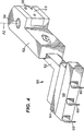
Der Schiebemechanismus ist in
An der Oberseite
Claims (6)
Applications Claiming Priority (2)
| Application Number | Priority Date | Filing Date | Title |
|---|---|---|---|
| US11/351,556 | 2006-02-10 | ||
| US11/351,556 US7426990B2 (en) | 2006-02-10 | 2006-02-10 | Pusher mechanism for I.S. machine |
Publications (2)
| Publication Number | Publication Date |
|---|---|
| DE102007001508A1 DE102007001508A1 (en) | 2007-08-16 |
| DE102007001508B4 true DE102007001508B4 (en) | 2012-07-12 |
Family
ID=37891219
Family Applications (1)
| Application Number | Title | Priority Date | Filing Date |
|---|---|---|---|
| DE102007001508A Expired - Fee Related DE102007001508B4 (en) | 2006-02-10 | 2007-01-10 | Sliding mechanism for an IS machine |
Country Status (9)
| Country | Link |
|---|---|
| US (1) | US7426990B2 (en) |
| JP (1) | JP4758365B2 (en) |
| AU (1) | AU2007200043A1 (en) |
| CZ (1) | CZ306058B6 (en) |
| DE (1) | DE102007001508B4 (en) |
| FR (1) | FR2897353B1 (en) |
| GB (1) | GB2435025B (en) |
| IT (1) | ITMI20070232A1 (en) |
| RU (1) | RU2435737C2 (en) |
Families Citing this family (8)
| Publication number | Priority date | Publication date | Assignee | Title |
|---|---|---|---|---|
| US7930902B2 (en) * | 2006-06-26 | 2011-04-26 | Emhart Glass S.A. | Mechanism for conveying an article |
| DE102008027911B4 (en) * | 2008-06-12 | 2011-06-16 | Heye International Gmbh | Device for pushing glass objects onto a conveyor belt |
| DE102010024301B4 (en) * | 2010-06-18 | 2012-04-05 | Heye International Gmbh | Device for pushing glass objects onto a conveyor belt |
| US9233868B2 (en) | 2011-02-23 | 2016-01-12 | Emhart Glass S.A. | System and method for controlling pusher parameters to adjust the placement of glass containers on the conveyor |
| ES2597239B1 (en) * | 2015-07-17 | 2017-10-24 | Avacon, S.A. | PACKAGING DRIER, FOR HOT GLASS MOVEMENT INSTALLATIONS |
| ITUA20164366A1 (en) * | 2016-06-14 | 2017-12-14 | Bottero Spa | GRIPPING BODY AND GROUP FOR THE TRANSFER OF GLASS CABLES |
| CN107777354B (en) * | 2017-11-24 | 2023-06-06 | 山东三金玻璃机械有限公司 | Bottle pulling device of bottle making machine and adsorbing bottle conveying method |
| CN107902390B (en) * | 2017-11-25 | 2019-11-05 | 山东三金玻璃机械有限公司 | A kind of bottle moving control method of the double servo bottle pulling mechanisms of vial bottle-making machine |
Citations (8)
| Publication number | Priority date | Publication date | Assignee | Title |
|---|---|---|---|---|
| US4414758A (en) * | 1981-03-23 | 1983-11-15 | Fritz Peter | Conveyor for cooling and removal of objects from an in-line sectional production machine |
| CZ288848B6 (en) * | 1996-10-17 | 2001-09-12 | Sklostroj Turnov Cz, S.R.O. | Shut-down mechanism of glass forming machine |
| US6702097B1 (en) * | 2002-09-04 | 2004-03-09 | Owens-Brockway Glass Container Inc. | Method of and apparatus for transferring articles from a fixed position to a moving conveyor |
| US20050193773A1 (en) * | 2004-03-03 | 2005-09-08 | Heye International Gmbh | Process and device for pushing hollow glass objects from a glass forming machine onto a conveyor belt |
| CZ295688B6 (en) * | 2004-06-18 | 2005-09-14 | Sklostroj Turnov Cz, S. R. O. | Dead plate mechanism of glass processing machine |
| WO2005085145A1 (en) * | 2004-03-02 | 2005-09-15 | Sklostroj Turnov Cz, S.R.O. | Pusher mechanism of glasswork forming machine |
| US20050199011A1 (en) * | 2004-03-12 | 2005-09-15 | Heye International Gmbh | Device for transferring hollow glass objects from a glass-forming machine onto a conveyor belt |
| EP1627859A1 (en) * | 2004-08-18 | 2006-02-22 | BOTTERO S.p.A. | Transfer apparatus for transferring glass articles |
Family Cites Families (7)
| Publication number | Priority date | Publication date | Assignee | Title |
|---|---|---|---|---|
| US3308922A (en) * | 1964-03-18 | 1967-03-14 | Brockway Glass Co Inc | Automatic lehr unloader |
| US3853213A (en) * | 1973-03-22 | 1974-12-10 | Anchor Hocking Corp | Lehr loader |
| US5125496A (en) * | 1986-10-14 | 1992-06-30 | Vitro Tec Fideicomiso | Article transfer pusher |
| US5429651A (en) * | 1992-12-30 | 1995-07-04 | I.M.T.E.C. Enterprises, Inc. | Apparatus for transferring glass articles from an is to a high speed transfer conveyor |
| US5992613A (en) * | 1997-09-16 | 1999-11-30 | Owens-Brockway Glass Container Inc. | Air cooled pusher bar support for LEHR loader |
| DE10138529A1 (en) * | 2000-09-28 | 2002-09-12 | Emhart Glass Sa | Mechanism for a glass container forming machine |
| US6604385B2 (en) * | 2001-04-10 | 2003-08-12 | Emhart Glass, S.A. | Control for an I.S. machine |
-
2006
- 2006-02-10 US US11/351,556 patent/US7426990B2/en not_active Expired - Fee Related
- 2006-12-29 CZ CZ2006-836A patent/CZ306058B6/en not_active IP Right Cessation
-
2007
- 2007-01-05 AU AU2007200043A patent/AU2007200043A1/en not_active Abandoned
- 2007-01-10 DE DE102007001508A patent/DE102007001508B4/en not_active Expired - Fee Related
- 2007-01-30 FR FR0752956A patent/FR2897353B1/en not_active Expired - Fee Related
- 2007-02-02 GB GB0702057A patent/GB2435025B/en not_active Expired - Fee Related
- 2007-02-07 JP JP2007027680A patent/JP4758365B2/en not_active Expired - Fee Related
- 2007-02-08 IT IT000232A patent/ITMI20070232A1/en unknown
- 2007-02-09 RU RU2007105079/11A patent/RU2435737C2/en not_active IP Right Cessation
Patent Citations (8)
| Publication number | Priority date | Publication date | Assignee | Title |
|---|---|---|---|---|
| US4414758A (en) * | 1981-03-23 | 1983-11-15 | Fritz Peter | Conveyor for cooling and removal of objects from an in-line sectional production machine |
| CZ288848B6 (en) * | 1996-10-17 | 2001-09-12 | Sklostroj Turnov Cz, S.R.O. | Shut-down mechanism of glass forming machine |
| US6702097B1 (en) * | 2002-09-04 | 2004-03-09 | Owens-Brockway Glass Container Inc. | Method of and apparatus for transferring articles from a fixed position to a moving conveyor |
| WO2005085145A1 (en) * | 2004-03-02 | 2005-09-15 | Sklostroj Turnov Cz, S.R.O. | Pusher mechanism of glasswork forming machine |
| US20050193773A1 (en) * | 2004-03-03 | 2005-09-08 | Heye International Gmbh | Process and device for pushing hollow glass objects from a glass forming machine onto a conveyor belt |
| US20050199011A1 (en) * | 2004-03-12 | 2005-09-15 | Heye International Gmbh | Device for transferring hollow glass objects from a glass-forming machine onto a conveyor belt |
| CZ295688B6 (en) * | 2004-06-18 | 2005-09-14 | Sklostroj Turnov Cz, S. R. O. | Dead plate mechanism of glass processing machine |
| EP1627859A1 (en) * | 2004-08-18 | 2006-02-22 | BOTTERO S.p.A. | Transfer apparatus for transferring glass articles |
Also Published As
| Publication number | Publication date |
|---|---|
| AU2007200043A1 (en) | 2007-08-30 |
| CZ306058B6 (en) | 2016-07-20 |
| CZ2006836A3 (en) | 2008-10-15 |
| RU2007105079A (en) | 2008-08-20 |
| GB0702057D0 (en) | 2007-03-14 |
| FR2897353A1 (en) | 2007-08-17 |
| DE102007001508A1 (en) | 2007-08-16 |
| JP4758365B2 (en) | 2011-08-24 |
| JP2007210883A (en) | 2007-08-23 |
| ITMI20070232A1 (en) | 2007-08-11 |
| FR2897353B1 (en) | 2014-02-14 |
| US20070187210A1 (en) | 2007-08-16 |
| RU2435737C2 (en) | 2011-12-10 |
| GB2435025B (en) | 2011-03-09 |
| GB2435025A (en) | 2007-08-15 |
| US7426990B2 (en) | 2008-09-23 |
Similar Documents
| Publication | Publication Date | Title |
|---|---|---|
| DE102007001508B4 (en) | Sliding mechanism for an IS machine | |
| DE102012206789A1 (en) | Table unit for a machine tool | |
| EP1751008A2 (en) | Machine for orientation and arrangement of objects | |
| EP1571130A2 (en) | Process and apparatus to transfer hollow glass product from a glass forming machine to a conveyor | |
| DE3233428C1 (en) | Feed and removal device, especially on presses | |
| EP0100307A1 (en) | Automatically operated apparatus for assembling, measuring, treating or the like of workpieces | |
| DE102008027911B4 (en) | Device for pushing glass objects onto a conveyor belt | |
| DE3218492C2 (en) | Machine for the production of copy templates for the edge grinding of spectacle lenses | |
| EP1577272A2 (en) | Transfer mechanism for glass articles from a station of an IS machine to a conveyor | |
| DE102010025168B3 (en) | Device for pushing glass objects onto a conveyor belt | |
| DE10233017A1 (en) | Eye buttonhole sewing machine | |
| DE2733353C2 (en) | Alignment and rotation station for automatic slot punching machines | |
| EP1577271B1 (en) | Transfer mechanism for glass articles from a station of an IS machine to a conveyor | |
| DE10118595B4 (en) | Machine tool with tool spindle and tool changer | |
| WO1995017352A1 (en) | Glass tube shaping device | |
| DE879941C (en) | Device for driving different speeds | |
| DE4313799A1 (en) | Leather working and hide cleaning machine - has a positioning system to move grinding disc for blade sharpening | |
| EP0856365A2 (en) | Device for conveying containers | |
| DE4312726C2 (en) | Pad Printing Machine | |
| DE525362C (en) | Speed change gear | |
| DE602004006003T2 (en) | EXHAUST DEVICE FOR CHOCOLATE AND THE SAME | |
| EP0003998A2 (en) | Machine for working a web of material by a welding tool | |
| DE1601064A1 (en) | Timing control | |
| DE19741812C2 (en) | Conveyor device for rotating objects | |
| DE3511560A1 (en) | DEVICE FOR DEPOSITING A CABLE |
Legal Events
| Date | Code | Title | Description |
|---|---|---|---|
| 8110 | Request for examination paragraph 44 | ||
| R018 | Grant decision by examination section/examining division | ||
| R020 | Patent grant now final |
Effective date: 20121013 |
|
| R119 | Application deemed withdrawn, or ip right lapsed, due to non-payment of renewal fee |