DE102006025552B4 - Hydropneumatic pressure accumulator - Google Patents
Hydropneumatic pressure accumulator Download PDFInfo
- Publication number
- DE102006025552B4 DE102006025552B4 DE200610025552 DE102006025552A DE102006025552B4 DE 102006025552 B4 DE102006025552 B4 DE 102006025552B4 DE 200610025552 DE200610025552 DE 200610025552 DE 102006025552 A DE102006025552 A DE 102006025552A DE 102006025552 B4 DE102006025552 B4 DE 102006025552B4
- Authority
- DE
- Germany
- Prior art keywords
- bellows
- pot
- storage enclosure
- storage
- edge
- Prior art date
- Legal status (The legal status is an assumption and is not a legal conclusion. Google has not performed a legal analysis and makes no representation as to the accuracy of the status listed.)
- Active
Links
Classifications
-
- F—MECHANICAL ENGINEERING; LIGHTING; HEATING; WEAPONS; BLASTING
- F16—ENGINEERING ELEMENTS AND UNITS; GENERAL MEASURES FOR PRODUCING AND MAINTAINING EFFECTIVE FUNCTIONING OF MACHINES OR INSTALLATIONS; THERMAL INSULATION IN GENERAL
- F16L—PIPES; JOINTS OR FITTINGS FOR PIPES; SUPPORTS FOR PIPES, CABLES OR PROTECTIVE TUBING; MEANS FOR THERMAL INSULATION IN GENERAL
- F16L55/00—Devices or appurtenances for use in, or in connection with, pipes or pipe systems
- F16L55/04—Devices damping pulsations or vibrations in fluids
- F16L55/045—Devices damping pulsations or vibrations in fluids specially adapted to prevent or minimise the effects of water hammer
- F16L55/05—Buffers therefor
- F16L55/052—Pneumatic reservoirs
- F16L55/053—Pneumatic reservoirs the gas in the reservoir being separated from the fluid in the pipe
-
- F—MECHANICAL ENGINEERING; LIGHTING; HEATING; WEAPONS; BLASTING
- F15—FLUID-PRESSURE ACTUATORS; HYDRAULICS OR PNEUMATICS IN GENERAL
- F15B—SYSTEMS ACTING BY MEANS OF FLUIDS IN GENERAL; FLUID-PRESSURE ACTUATORS, e.g. SERVOMOTORS; DETAILS OF FLUID-PRESSURE SYSTEMS, NOT OTHERWISE PROVIDED FOR
- F15B1/00—Installations or systems with accumulators; Supply reservoir or sump assemblies
- F15B1/02—Installations or systems with accumulators
- F15B1/04—Accumulators
- F15B1/08—Accumulators using a gas cushion; Gas charging devices; Indicators or floats therefor
- F15B1/10—Accumulators using a gas cushion; Gas charging devices; Indicators or floats therefor with flexible separating means
- F15B1/103—Accumulators using a gas cushion; Gas charging devices; Indicators or floats therefor with flexible separating means the separating means being bellows
-
- F—MECHANICAL ENGINEERING; LIGHTING; HEATING; WEAPONS; BLASTING
- F15—FLUID-PRESSURE ACTUATORS; HYDRAULICS OR PNEUMATICS IN GENERAL
- F15B—SYSTEMS ACTING BY MEANS OF FLUIDS IN GENERAL; FLUID-PRESSURE ACTUATORS, e.g. SERVOMOTORS; DETAILS OF FLUID-PRESSURE SYSTEMS, NOT OTHERWISE PROVIDED FOR
- F15B2201/00—Accumulators
- F15B2201/20—Accumulator cushioning means
- F15B2201/205—Accumulator cushioning means using gas
-
- F—MECHANICAL ENGINEERING; LIGHTING; HEATING; WEAPONS; BLASTING
- F15—FLUID-PRESSURE ACTUATORS; HYDRAULICS OR PNEUMATICS IN GENERAL
- F15B—SYSTEMS ACTING BY MEANS OF FLUIDS IN GENERAL; FLUID-PRESSURE ACTUATORS, e.g. SERVOMOTORS; DETAILS OF FLUID-PRESSURE SYSTEMS, NOT OTHERWISE PROVIDED FOR
- F15B2201/00—Accumulators
- F15B2201/30—Accumulator separating means
- F15B2201/315—Accumulator separating means having flexible separating means
- F15B2201/3153—Accumulator separating means having flexible separating means the flexible separating means being bellows
-
- F—MECHANICAL ENGINEERING; LIGHTING; HEATING; WEAPONS; BLASTING
- F15—FLUID-PRESSURE ACTUATORS; HYDRAULICS OR PNEUMATICS IN GENERAL
- F15B—SYSTEMS ACTING BY MEANS OF FLUIDS IN GENERAL; FLUID-PRESSURE ACTUATORS, e.g. SERVOMOTORS; DETAILS OF FLUID-PRESSURE SYSTEMS, NOT OTHERWISE PROVIDED FOR
- F15B2201/00—Accumulators
- F15B2201/40—Constructional details of accumulators not otherwise provided for
- F15B2201/41—Liquid ports
- F15B2201/411—Liquid ports having valve means
Landscapes
- Engineering & Computer Science (AREA)
- General Engineering & Computer Science (AREA)
- Mechanical Engineering (AREA)
- Physics & Mathematics (AREA)
- Fluid Mechanics (AREA)
- Supply Devices, Intensifiers, Converters, And Telemotors (AREA)
Abstract
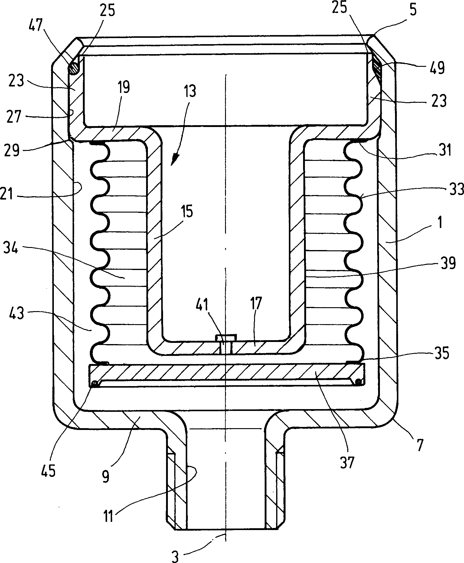
Hydropneumatischer Druckspeicher mit einem innerhalb des Speichergehäuses (1) bewegbaren Trennelement in Form eines Balges (33), insbesondere Metallbalges, der einen Arbeitsraum, insbesondere Gasraum (34), von einem weiteren Arbeitsraum, insbesondere Ölraum (43), separiert, wobei der Balg (33) mit seinem einen freien Ende (35) an einem Schließelement (37), mittels dem in Abhängigkeit von Bewegungen des Balges (33) eine Speichergehäuseöffnung (11) wechselweise freigebbar und verschließbar ist, und mit seinem zweiten freien Ende (31) an einem Wandteil (19) innerhalb des Speichergehäuses (1) angreift, wobei innerhalb des Speichergehäuses (1) ein trogartiger Haltekörper (13) angeordnet ist, der mit dem Speichergehäuse (1) fest verbunden ist, wobei das Schließelement (37) zwischen der Speichergehäuseöffnung (11) und dem Haltekörper (13) bewegbar angeordnet ist, wobei der trogartige Haltekörper einen Topf (15) mit einer sich längs der Innenseite des Balges (33) erstreckenden Seitenwand (39), einem dem Schließelement (37) zugekehrten, geschlossenen Boden (17) und einem offenen Ende aufweist, wobei der Topf (15) am offenen...hydropneumatic Pressure accumulator with a within the storage housing (1) movable separating element in the form of a bellows (33), in particular metal bellows, one working space, in particular gas space (34), of another Working space, especially oil room (43), the bellows (33) having its one free end (35) on a closing element (37), by means of dependence movements of the bellows (33) a storage housing opening (11) alternately releasable and lockable is, and with its second free end (31) on a wall part (19) inside the storage enclosure (1) engages, wherein within the storage housing (1) a trough-like holding body (13) is arranged, which is fixedly connected to the storage housing (1), the closing element (37) between the storage case opening (11) and the holding body (13) is movably arranged, wherein the trough-like holding body a Pot (15) with a longitudinally the inside of the bellows (33) extending side wall (39), a the closing element (37) facing, closed bottom (17) and an open end having the pot (15) at the open ...
Description
Die Erfindung bezieht sich auf einen hydropneumatischen Druckspeicher mit einem innerhalb des Speichergehäuses bewegbaren Trennelement in Form eines Balges, insbesondere Metallbalges, der einen Arbeitsraum, insbesondere Gasraum, von einem weiteren Arbeitsraum, insbesondere Ölraum, separiert, gemäß der Merkmalsausgestaltung des Oberbegriffes des Patentanspruches 1.The The invention relates to a hydropneumatic pressure accumulator with a movable within the storage enclosure separating element in the form of a bellows, in particular metal bellows, a working space, in particular gas space, separated from another working space, in particular oil space, according to the feature design the preamble of claim 1.
Durch
die
Bekanntermaßen muß bei Balgspeichern mit Gummibälgen oder Metallbälgen darauf geachtet werden, dass Überlastungen des Balges vermieden werden. Insbesondere bei einem Einsatz derartiger Druckspeicher als Pulsationsdämpfer, wo sich im Betrieb Wechselbelastungen des Balges ergeben, ist die Betriebssicherheit über lange Betriebszeiträume hinweg nicht immer gewährleistet. Zwar genügt die bekannte Lösung den dahingehenden Anforderungen, jedoch ist der Herstellaufwand für die bekannte Lösung insoweit erhöht, als die vorbereitete Baueinheit aus trogartigem Haltekörper und Metallbalg an die untere Gehäuseplatte des Speichergehäuses mit der Ventilaufnahme anzuschweißen ist, was es wiederum notwendig macht, in einem weiteren Herstellschritt das sonstige Speichergehäuse auf die Baueinheit aufzusetzen und mit der Gehäuseplatte zu verschweißen. Um einen druckdichten Aufbau zu gewährleisten, ist die dahingehende Verbindungsschweißnaht sorgfältig auszuführen und ferner ist sicherzustellen, dass nicht ungewollt Schweißspritzer in das Innere des Speichergehäuses eingetragen werden mit der Folge, dass das empfindliche Balgmaterial entsprechend geschädigt werden könnte.As is known, bellows storage is required with rubber bellows or metal bellows be careful that overloads of the bellows are avoided. Especially when using such pressure accumulator as a pulsation damper, where arise during operation alternating loads of the bellows, is the Operational safety over long operating periods not always guaranteed. It is enough the known solution the pertinent requirements, however, is the manufacturing effort for the known solution insofar increased, as the prepared assembly of trough-like holding body and Metal bellows to the lower housing plate of the storage enclosure welding with the valve seat is what it is necessary to do again makes, in a further manufacturing step on the other storage enclosure set up the unit and weld it to the housing plate. Around to ensure a pressure tight construction the perturbation weld shall be carefully designed and further that does not unintentionally spatter in the interior of the storage enclosure be registered with the consequence that the delicate bellows material damaged accordingly could be.
Zwar
ist in der
Ausgehend von diesem Stand der Technik liegt der Erfindung die Aufgabe zugrunde, einen Druckspeicher der betrachteten Art zu schaffen, der bei guten Betriebseigenschaften eine kostengünstige Fertigung und einen balgschonenden Betrieb ermöglicht. Eine dahingehende Aufgabe löst ein hydropneumatischer Druckspeicher mit der Merkmalsausgestaltung des Patentanspruches 1 in seiner Gesamtheit.outgoing From this prior art, the invention is based on the object to create an accumulator of the type considered, the good at Operating characteristics a cost-effective production and a bellows-friendly operation allows. This task solves a hydropneumatic accumulator with the feature design of claim 1 in its entirety.
Dadurch, dass gemäß dem kennzeichnenden Teil des Patentanspruches 1 die Gehäusewand des Speichergehäuses an ihrem offenen Ende radial nach innen über den Endrand des Fortsatzes verformt ist, und dass an der Innenseite des Speichergehäuses eine Stufe ausgebildet ist, die einen erweiterten, den axialen Fortsatz des Randes des Topfes aufnehmenden Innenwandabschnitt sowie eine Anschlagschulter für eine formschlüssige Sicherung des Randes des Topfes bildet, läßt sich die Einsatzbaugruppe, gebildet aus Haltekörper, Balg und Schließelement, in das Innere des Speichergehäuses einbringen und ohne irgendwelche Schweißarbeiten zwischen dem nach innen zu verformenden Endrand und der genannten absatzartigen Stufe in der Gehäusewand des Speichergehäuses an dieser definiert festlegen. Die dahingehende Bauweise erlaubt insoweit eine besonders kostengünstige Fertigung und auf gegebenenfalls das Balgmaterial schädigende Schweißverfahren kann bei der Verbindung von trogartigem Haltekörper mit Speichergehäuse völlig verzichtet werden.Thereby, that according to the characterizing Part of claim 1, the housing wall of the storage enclosure its open end radially inwardly beyond the end edge of the extension is deformed, and that on the inside of the storage enclosure a Stage is formed, which has an extended, the axial extension the edge of the pot receiving inner wall section and a Stop shoulder for a form-fitting Securing the edge of the pot forms the insert assembly, formed from holding body, Bellows and closing element, into the interior of the storage enclosure bring in and without any welding between the post inside to be deformed end edge and said heel-like step in the housing wall of the storage enclosure set to this defined. The pertinent construction allowed insofar a particularly cost-effective Manufacturing and possibly damaging the bellows material welding processes can be completely dispensed with the connection of trough-like holding body with storage housing become.
Dadurch, dass der trogartige Haltekörper einen Topf mit einer sich längs der Innenseite des Balges erstreckenden Seitenwand, einem dem Schließelement zugekehrten, geschlossenen Boden und einem offenen Ende aufweist, erweist sich eine dahingehende Gestaltung in mehrerer Hinsicht als vorteilhaft. Dadurch, dass der Balg mit seiner Innenseite die im Durchmesser gegenüber dem sonstigen Trog des Haltekörpers verbreiterte Seitenwand des Topfes umringt, ist der Balg bei einem auf seiner Außenseite herrschenden Überdruck auch mechanisch auf der Außenseite des Topfes auf gesamter Länge abgestützt. Wenn die Innenseite des Balges an den Gasraum angrenzt, ermöglicht dies wiederum den Gas-Vorfülldruck nachträglich, wenn bereits der Anschluß an ein Ölsystem vorgenommen ist, aufzubauen oder den erforderlichen Fülldruck zu erhöhen.Due to the fact that the trough-like holding body has a pot with a side wall extending along the inside of the bellows, a closed bottom facing the closing element and an open end, such an arrangement proves to be advantageous in several respects. Due to the fact that the bellows surrounds the side wall of the pot widened in diameter with respect to the other trough of the holding body, the bellows is also mechanically supported on the outside of the pot over its entire length in the event of overpressure prevailing on its outside. When the inside of the bellows to the gas adjacent space, this in turn allows the gas pre-filling subsequently, if the connection to an oil system is already made to build up or to increase the required filling pressure.
Die erfindungsgemäße Anordnung ist so getroffen, dass der Rand des Topfes an seinem radial außen liegenden Ende in einen an der Innenseite des Speichergehäuses anliegenden, sich in Axialrichtung erstreckenden Fortsatz übergeht, der durch an der Innenseite des Speichergehäuses vorgesehene Ausgestaltungen gegen Axialverschiebungen kraft- oder formschlüssig gesichert ist. Das Speichergehäuse bildet einen mechanischen Anschlag für die Bewegung des Schließelementes aus und die derart gebildete Hubbegrenzung für Auszieh- und Einfahrbewegungen des Balges bildet einen wirksamen Schutz gegen Überlastungsprobleme aus, so dass der Balg dünnwandig und damit flexibel gestaltet werden kann, so dass sich ein besonders gutes Ansprechverhalten im Betrieb ergibt, was eine Anwendbarkeit des Erfindungsgegenstandes als Pulsationsdämpfer besonders begünstigt.The inventive arrangement is made so that the edge of the pot at its radially outer End in a voltage applied to the inside of the storage enclosure, extending in the axial direction Extension passes, the provided by on the inside of the storage enclosure embodiments secured against axial displacements non-positively or positively. The storage enclosure forms a mechanical stop for the movement of the closing element from and the stroke limit thus formed for pull-out and retraction movements of the bellows provides effective protection against overload problems, so that the bellows thin-walled and thus can be made flexible, so that is a special good response in operation results, which is an applicability of the subject invention as Pulsationsdämpfer particularly favored.
Durch die Wahl der Tiefe des mit dem Speichergehäuse fest verbundenen Troges lassen sich auf konstruktiv besonders einfache Weise die gewünschten Volumina der innerhalb des Speichergehäuses befindlichen Räume erreichen, also speziell das Volumen des an die Außenseite des Troges angrenzenden Arbeitsraumes in Entsprechung zur Tiefe des Troges, wobei bei Gasdruckspeichern das Verhalten (Charakteristik) gesteuert werden kann (p-V-Kurve).By the choice of the depth of the trough firmly connected to the storage enclosure can be in a structurally particularly simple way the desired Reach volumes of the spaces inside the storage enclosure, so specifically the volume of the adjacent to the outside of the trough Working space corresponding to the depth of the trough, with gas pressure accumulators the behavior (characteristic) can be controlled (p-V curve).
Vorzugsweise besitzt der erfindungsgemäße Druckspeicher eine kreiszylinderförmige Gestalt, wobei der trogartige Haltekörper gleichfalls kreiszylindrisch geformt und zu einer zentralen Längsachse des Speichergehäuses konzentrisch ist. Wenn die Innenseite des Balges an den Gasraum angrenzt, ermöglicht dies wiederum den Gas-Vorfülldruck nachträglich, wenn bereits der Anschluß an ein Ölsystem vorgenommen ist, aufzubauen oder den erforderlichen Fülldruck zu erhöhen.Preferably has the pressure accumulator according to the invention a circular cylindrical Shape, wherein the trough-like holding body also circular cylindrical shaped and to a central longitudinal axis of the storage enclosure is concentric. When the inside of the bellows to the gas space adjacent, allows this in turn the gas pre-charge pressure subsequently, if already the connection to an oil system is made to build or the required inflation pressure to increase.
Die Anordnung kann so getroffen sein, dass der Fortsatz des Randes des Topfes an seiner der Innenseite des Speichergehäuses zugewandten Außen seite radial nach innen versetzte Bezirke als Sitz für Dichtelemente aufweist. In besonders vorteilhafter Weise bildet dadurch der Haltekörper in Zusatzfunktion den dichten Abschluss des Speichergehäuses, d. h. dass am betreffenden Ende des Speichergehäuses kein Gehäusedeckel, beispielsweise durch Anschweißen, angebracht zu werden braucht.The Arrangement can be made such that the extension of the edge of the Pot on its inside of the storage enclosure facing the outer side Having radially inwardly offset districts as a seat for sealing elements. In Particularly advantageous manner thereby forms the holding body in Additional function the tight completion of the storage enclosure, d. H. that at the relevant end of the storage enclosure no housing cover, for example, by welding, needs to be installed.
In besonders einfacher und vorteilhafter Weise kann die Dichtverbindung in der Weise gestaltet sein, dass der Fortsatz zur Bildung einer Kammer, die ein betreffendes Dichtelement, vorzugsweise O-Ring, umfasst, durch eine Wölbung verformt ist, die sich abschnittsweise radial nach innen und radial nach außen erstreckt. Eine derartige, auf einfache Weise ausbildbare Kammerung eines betreffenden Dichtelementes gewährleistet eine besonders betriebssichere Abdichtung.In particularly simple and advantageous manner, the sealing connection be designed in such a way that the extension to form a Chamber, a relevant sealing element, preferably O-ring, includes, by a vault is deformed, the sections radially inward and radially Outside extends. Such, in a simple manner ausbildbare chambering a relevant sealing element ensures a particularly reliable Seal.
Bei vorteilhaften Ausführungsbeispielen kann die Anordnung so getroffen sein, dass der Gasraum an das Innere des Balges angrenzt und das Schließelement eine das zugeordnete Ende des Balges gasdicht abschließende Verschlussplatte ist.at advantageous embodiments can the arrangement be made so that the gas space to the interior of the bellows adjoins and the closing element an associated End of the bellows gas-tight final closure plate is.
In besonders vorteilhafter Weise kann diese Verschlussplatte als Plattenventilkörper ausgebildet sein, der bei Anlage am Bodenteil des Speichergehäuses die im Bodenteil ausgebildete Gehäuseöffnung schließt, die den Zugang zu dem den Balg umgebenden Ölraum bildet. Wenn im Betrieb des erfindungsgemäßen Druckspeichers einmal das Druckgleichgewicht zwischen Gas-Vorfülldruck im Gasraum und Hydraulikdruck im Ölraum hergestellt ist, so dass sich die Verschlussplatte zwischen ihren vorgegebenen Endstellungen befindet, wobei die Gehäuseöffnung nicht gesperrt ist, dann ist am Balg Druckausgleich zwischen Innenseite und Außenseite gegeben. In vorteilhafter Weise bleibt dieser Druckausgleich auch dann erhalten, wenn der Hydraulikdruck auf der Ölseite gegenüber dem Gas-Vorfülldruck abfallen sollte, weil dies zum Sperren der Gehäuseöffnung führt, so dass kein weiterer Druckabfall im Ölraum stattfinden kann.In Particularly advantageously, this closure plate can be designed as a plate valve body, the system formed at the bottom of the storage case in the bottom part Housing opening closes, the forms access to the oil space surrounding the bellows. When in operation the pressure accumulator according to the invention once the pressure balance between gas pre-charge pressure in the gas space and hydraulic pressure in the oil room is made so that the closure plate between their predetermined end positions, wherein the housing opening is not is locked, then is on the bellows pressure equalization between inside and given outside. Advantageously, this pressure compensation is maintained even then when the hydraulic pressure on the oil side across from the gas pre-charge pressure should fall off, because this leads to the blocking of the housing opening, so that no further Pressure drop in the oil room can take place.
Nachstehend ist die Erfindung anhand von in der Zeichnung dargestellten Ausführungsbeispielen im Einzelnen erläutert. Es zeigen:below the invention with reference to embodiments shown in the drawing in Individual explained. Show it:
In
den Fig. ist das Speichergehäuse
eines erfindungsgemäßen Druckspeichers
mit
Beim
erfindungsgemäßen Druckspeicher sind
sämtliche
innerhalb des Speichergehäuses
Wie
die Fig. zeigen, ist der Haltekörper
An
der dem Innenraum des Speichergehäuses
Bei
an der Speichergehäuseöffnung
In
den Fig. sind vier verschiedene Ausführungsbeispiele der Ausbildung
einer Abbildung der Außenseite
des Fortsatzes
Die
Wie
bereits erwähnt,
kann das Speichergehäuse
Claims (8)
Priority Applications (1)
| Application Number | Priority Date | Filing Date | Title |
|---|---|---|---|
| DE200610025552 DE102006025552B4 (en) | 2006-06-01 | 2006-06-01 | Hydropneumatic pressure accumulator |
Applications Claiming Priority (1)
| Application Number | Priority Date | Filing Date | Title |
|---|---|---|---|
| DE200610025552 DE102006025552B4 (en) | 2006-06-01 | 2006-06-01 | Hydropneumatic pressure accumulator |
Publications (2)
| Publication Number | Publication Date |
|---|---|
| DE102006025552A1 DE102006025552A1 (en) | 2007-12-13 |
| DE102006025552B4 true DE102006025552B4 (en) | 2008-07-31 |
Family
ID=38663609
Family Applications (1)
| Application Number | Title | Priority Date | Filing Date |
|---|---|---|---|
| DE200610025552 Active DE102006025552B4 (en) | 2006-06-01 | 2006-06-01 | Hydropneumatic pressure accumulator |
Country Status (1)
| Country | Link |
|---|---|
| DE (1) | DE102006025552B4 (en) |
Families Citing this family (5)
| Publication number | Priority date | Publication date | Assignee | Title |
|---|---|---|---|---|
| DE102008016354A1 (en) * | 2007-08-28 | 2009-05-28 | Continental Teves Ag & Co. Ohg | Pressure reservoir for use in brake system of motor vehicle, has metal bellow cooperating with protection valve that is formed to prevent supply of fluid by closing supply opening during reaching preset deformation |
| DE102009021463A1 (en) | 2009-05-15 | 2010-11-18 | Hydac Technology Gmbh | hydraulic accumulator |
| DE102009056956B4 (en) * | 2009-12-07 | 2019-02-14 | Arianegroup Gmbh | Damping element for a fuel supply pipe system of a space propulsion system |
| DE102011117752A1 (en) * | 2011-11-05 | 2013-05-08 | Hydac Technology Gmbh | Hydraulic accumulator in the form of a bellows accumulator |
| CN110030379B (en) * | 2019-04-17 | 2021-07-06 | 上海进纬仪器设备有限公司 | A bellows tube and an automotive air-conditioning compressor solenoid valve with the bellows |
Citations (3)
| Publication number | Priority date | Publication date | Assignee | Title |
|---|---|---|---|---|
| WO2001055602A1 (en) * | 2000-01-29 | 2001-08-02 | Hydac Technology Gmbh | Hydropneumatic accumulator |
| DE10020903A1 (en) * | 2000-04-28 | 2002-03-07 | Continental Teves Ag & Co Ohg | Accumulator |
| DE10060558A1 (en) * | 2000-11-29 | 2002-06-13 | Bosch Gmbh Robert | Pressure reservoir for vehicle braking system has pressure medium chamber at least partly bounded by partly permeable material enabling gas to escape and preventing pressure medium from escaping |
-
2006
- 2006-06-01 DE DE200610025552 patent/DE102006025552B4/en active Active
Patent Citations (3)
| Publication number | Priority date | Publication date | Assignee | Title |
|---|---|---|---|---|
| WO2001055602A1 (en) * | 2000-01-29 | 2001-08-02 | Hydac Technology Gmbh | Hydropneumatic accumulator |
| DE10020903A1 (en) * | 2000-04-28 | 2002-03-07 | Continental Teves Ag & Co Ohg | Accumulator |
| DE10060558A1 (en) * | 2000-11-29 | 2002-06-13 | Bosch Gmbh Robert | Pressure reservoir for vehicle braking system has pressure medium chamber at least partly bounded by partly permeable material enabling gas to escape and preventing pressure medium from escaping |
Also Published As
| Publication number | Publication date |
|---|---|
| DE102006025552A1 (en) | 2007-12-13 |
Similar Documents
| Publication | Publication Date | Title |
|---|---|---|
| DE102017209609B4 (en) | Vibration damper with adjustable damping force | |
| DE3133839C2 (en) | ||
| EP1250533B1 (en) | Hydropneumatic accumulator | |
| DE102019007454A1 (en) | Valve for pressure equalization and / or for emergency venting of a container, preferably a housing of a battery of electric vehicles, as well as a container with such a valve | |
| DE3004307A1 (en) | SELF-PUMPING HYDROPNEUMATIC TELESCOPIC SPRING DAMPER ELEMENT WITH INTERNAL LEVEL CONTROL | |
| DE102010002937B3 (en) | Vibration damper with stroke-dependent damping force | |
| DE102014208367B4 (en) | Damping valve device for a vibration damper | |
| WO2010066321A1 (en) | Hydraulic accumulator, in particular bellows accumulator | |
| EP1709334A1 (en) | Pressure accumulator, especially pulsation damper | |
| DE102009049547B3 (en) | Hydropneumatic pressure accumulator | |
| EP2773874B1 (en) | Hydraulic accumulator in form of a bellows accumulator | |
| DE102006025552B4 (en) | Hydropneumatic pressure accumulator | |
| DE102015205447A1 (en) | Vibration damper and motor vehicle | |
| EP2519747B1 (en) | Guiding device for metal bellows | |
| EP3317559B1 (en) | Hydraulic vibration damper | |
| DE102017213915A1 (en) | Pressure fluid accumulator, in particular for storing brake fluid in a brake circuit of an electronically slip-controllable vehicle brake system | |
| EP1354139A2 (en) | Hydraulic accumulator, especially bladder accumulator | |
| DE102015001435A1 (en) | Hydraulic accumulator, in particular for a chassis of a vehicle | |
| WO2016173697A1 (en) | Hydraulic accumulator | |
| EP2769102B1 (en) | Hydraulic accumulator in the form of a bellows accumulator | |
| DE202007008175U1 (en) | Hydropneumatic pressure accumulator | |
| DE102016002999B3 (en) | Storage device, mounting kit for producing a storage device and method for producing a storage device | |
| DE4015719A1 (en) | Valve play compensating mechanism - has cam which actuates cap which houses plunger which actuates valve | |
| DE102019128962A1 (en) | Control valve | |
| DE102015113617A1 (en) | Connecting rod and internal combustion engine |
Legal Events
| Date | Code | Title | Description |
|---|---|---|---|
| R012 | Request for examination validly filed | ||
| OP8 | Request for examination as to paragraph 44 patent law | ||
| R016 | Response to examination communication | ||
| R018 | Grant decision by examination section/examining division | ||
| 8364 | No opposition during term of opposition | ||
| R020 | Patent grant now final |
Effective date: 20081031 |