DE102005007767B4 - Discharge lamp with a specially shaped cathode to prevent the fluctuation phenomenon of the arc - Google Patents
Discharge lamp with a specially shaped cathode to prevent the fluctuation phenomenon of the arc Download PDFInfo
- Publication number
- DE102005007767B4 DE102005007767B4 DE102005007767A DE102005007767A DE102005007767B4 DE 102005007767 B4 DE102005007767 B4 DE 102005007767B4 DE 102005007767 A DE102005007767 A DE 102005007767A DE 102005007767 A DE102005007767 A DE 102005007767A DE 102005007767 B4 DE102005007767 B4 DE 102005007767B4
- Authority
- DE
- Germany
- Prior art keywords
- cathode
- convex parts
- concave
- discharge lamp
- convex
- Prior art date
- Legal status (The legal status is an assumption and is not a legal conclusion. Google has not performed a legal analysis and makes no representation as to the accuracy of the status listed.)
- Active
Links
- 230000007423 decrease Effects 0.000 claims description 11
- 238000004031 devitrification Methods 0.000 description 11
- 230000000694 effects Effects 0.000 description 9
- 238000002474 experimental method Methods 0.000 description 9
- 239000007789 gas Substances 0.000 description 9
- 230000005684 electric field Effects 0.000 description 7
- 238000004519 manufacturing process Methods 0.000 description 7
- XKRFYHLGVUSROY-UHFFFAOYSA-N Argon Chemical compound [Ar] XKRFYHLGVUSROY-UHFFFAOYSA-N 0.000 description 4
- QSHDDOUJBYECFT-UHFFFAOYSA-N mercury Chemical compound [Hg] QSHDDOUJBYECFT-UHFFFAOYSA-N 0.000 description 4
- 229910052753 mercury Inorganic materials 0.000 description 4
- 229910052756 noble gas Inorganic materials 0.000 description 4
- 239000000126 substance Substances 0.000 description 4
- 229910052724 xenon Inorganic materials 0.000 description 4
- FHNFHKCVQCLJFQ-UHFFFAOYSA-N xenon atom Chemical compound [Xe] FHNFHKCVQCLJFQ-UHFFFAOYSA-N 0.000 description 4
- 230000015556 catabolic process Effects 0.000 description 3
- 239000011261 inert gas Substances 0.000 description 3
- 238000009413 insulation Methods 0.000 description 3
- 239000004065 semiconductor Substances 0.000 description 3
- ZSLUVFAKFWKJRC-IGMARMGPSA-N 232Th Chemical compound [232Th] ZSLUVFAKFWKJRC-IGMARMGPSA-N 0.000 description 2
- AANMVENRNJYEMK-UHFFFAOYSA-N 4-propan-2-ylcyclohex-2-en-1-one Chemical compound CC(C)C1CCC(=O)C=C1 AANMVENRNJYEMK-UHFFFAOYSA-N 0.000 description 2
- 229910052776 Thorium Inorganic materials 0.000 description 2
- 229910052786 argon Inorganic materials 0.000 description 2
- 239000013078 crystal Substances 0.000 description 2
- 238000010891 electric arc Methods 0.000 description 2
- 238000010438 heat treatment Methods 0.000 description 2
- 238000000034 method Methods 0.000 description 2
- 150000002835 noble gases Chemical class 0.000 description 2
- NJPPVKZQTLUDBO-UHFFFAOYSA-N novaluron Chemical compound C1=C(Cl)C(OC(F)(F)C(OC(F)(F)F)F)=CC=C1NC(=O)NC(=O)C1=C(F)C=CC=C1F NJPPVKZQTLUDBO-UHFFFAOYSA-N 0.000 description 2
- 230000002093 peripheral effect Effects 0.000 description 2
- 230000003716 rejuvenation Effects 0.000 description 2
- WFKWXMTUELFFGS-UHFFFAOYSA-N tungsten Chemical compound [W] WFKWXMTUELFFGS-UHFFFAOYSA-N 0.000 description 2
- 229910052721 tungsten Inorganic materials 0.000 description 2
- 239000010937 tungsten Substances 0.000 description 2
- 230000015572 biosynthetic process Effects 0.000 description 1
- 238000001816 cooling Methods 0.000 description 1
- 238000011161 development Methods 0.000 description 1
- 230000018109 developmental process Effects 0.000 description 1
- 230000002996 emotional effect Effects 0.000 description 1
- 238000000227 grinding Methods 0.000 description 1
- 238000005286 illumination Methods 0.000 description 1
- 229910052743 krypton Inorganic materials 0.000 description 1
- DNNSSWSSYDEUBZ-UHFFFAOYSA-N krypton atom Chemical compound [Kr] DNNSSWSSYDEUBZ-UHFFFAOYSA-N 0.000 description 1
- 239000000463 material Substances 0.000 description 1
- 239000000155 melt Substances 0.000 description 1
- 238000002844 melting Methods 0.000 description 1
- 230000008018 melting Effects 0.000 description 1
- 238000002360 preparation method Methods 0.000 description 1
- 238000007789 sealing Methods 0.000 description 1
- 230000007704 transition Effects 0.000 description 1
- 238000002834 transmittance Methods 0.000 description 1
- 238000009281 ultraviolet germicidal irradiation Methods 0.000 description 1
- 230000000007 visual effect Effects 0.000 description 1
Images


Classifications
-
- H—ELECTRICITY
- H01—ELECTRIC ELEMENTS
- H01J—ELECTRIC DISCHARGE TUBES OR DISCHARGE LAMPS
- H01J61/00—Gas-discharge or vapour-discharge lamps
- H01J61/02—Details
- H01J61/04—Electrodes; Screens; Shields
- H01J61/06—Main electrodes
- H01J61/073—Main electrodes for high-pressure discharge lamps
- H01J61/0732—Main electrodes for high-pressure discharge lamps characterised by the construction of the electrode
-
- H—ELECTRICITY
- H01—ELECTRIC ELEMENTS
- H01J—ELECTRIC DISCHARGE TUBES OR DISCHARGE LAMPS
- H01J61/00—Gas-discharge or vapour-discharge lamps
- H01J61/84—Lamps with discharge constricted by high pressure
- H01J61/86—Lamps with discharge constricted by high pressure with discharge additionally constricted by close spacing of electrodes, e.g. for optical projection
-
- H—ELECTRICITY
- H01—ELECTRIC ELEMENTS
- H01J—ELECTRIC DISCHARGE TUBES OR DISCHARGE LAMPS
- H01J2893/00—Discharge tubes and lamps
- H01J2893/0064—Tubes with cold main electrodes (including cold cathodes)
- H01J2893/0065—Electrode systems
- H01J2893/0066—Construction, material, support, protection and temperature regulation of electrodes; Electrode cups
Landscapes
- Discharge Lamp (AREA)
Abstract
Entladungslampe, welche eine Leuchtröhre (11) aufweist, in welcher ein Entladungsraum (5) gebildet und in welcher eine Kathode (20) und eine Anode (15) gegenüberliegend angeordnet sind, wobei die Kathode einen sich verjüngenden Teil aufweist, dessen Durchmesser sich in Richtung auf die Spitze verkleinert, wobei in dem sich verjüngenden Teil (21) ein sich über dessen gesamten Umfang in der Umfangsrichtung erstreckender Bereich (30) mit unterschiedlichen Durchmessern ausgebildet ist, der konkav-konvexe Teile (31A, 31B) aufweist, dadurch gekennzeichnet, dass die konkav-konvexen Teile (31A, 31B) jeweils aus einer Mehrzahl (32) konvexer Teile (33) bestehen, die in Achsrichtung der Kathode (20) nebeneinander angeordnet sind, wobei die konkav-konvexen Teile (31A, 31B) im Querschnitt, welcher die Mittelachse (C) der Kathode einschließt, in der Weise angeordnet sind, dass die Eckpunkte eines jeden konvexen Teils (33) sich innerhalb der verlängerten Kantenlinie (R) des sich verjüngenden Teils (21) befinden und die Mantelkurve (L), welche die Eckpunkte verbindet,...Discharge lamp which has an arc tube (11) in which a discharge space (5) is formed and in which a cathode (20) and an anode (15) are arranged opposite one another, the cathode having a tapering part whose diameter tapers in the direction reduced to the tip, wherein in the tapering part (21) a region (30) extending over its entire circumference in the circumferential direction with different diameters is formed which has concavo-convex parts (31A, 31B), characterized in that the concavo-convex parts (31A, 31B) each consist of a plurality (32) of convex parts (33) which are arranged next to one another in the axial direction of the cathode (20), the concavo-convex parts (31A, 31B) in cross section, which includes the central axis (C) of the cathode, are arranged in such a way that the corner points of each convex part (33) are within the extended edge line (R) of the tapered part (2 1) and the jacket curve (L), which connects the corner points, ...
Description
Die Erfindung betrifft eine Entladungslampe. Die Erfindung betrifft insbesondere eine Entladungslampe vom Kurzbogentyp, welche beispielsweise als Lichtquelle bei einer UV-Bestrahlungs-Behandlung in der fotochemischen Industrie, bei der Halbleiterherstellung und dergleichen oder als Lichtquelle bei Projektionen wie bei einem Projektor oder dergleichen verwendet wird.The invention relates to a discharge lamp. More particularly, the invention relates to a discharge lamp of the short arc type which is used, for example, as a light source in a UV irradiation treatment in the photochemical industry, semiconductor manufacturing and the like or as a light source in projections such as a projector or the like.
Eine Entladungslampe
Die Kathode
Bei einer derartigen Entladungslampe vom Kurzbogentyp
Nachfolgend wird das Entladungsphänomen beim Starten der Lampe konkret beschrieben.Hereinafter, the discharge phenomenon at the start of the lamp will be concretely described.
Unmittelbar nachdem der Isolationsdurchschlag zwischen der Kathode
Dadurch, dass die Kathode
Bei einer Entladungslampe vom Kurzbogentyp
Wenn der Startpunkt P des Lichtbogens A an der vorstehend beschriebenen Position gebildet wird, wird, wie vorstehend beschrieben wurde, der Lichtbogen A beispielsweise in der Weise gebildet, dass er sich entlang der Innenoberfläche der Leuchtröhre
- (1) Die Kontaktstelle des Lichtbogens A mit der
Leuchtröhre 41 unterliegt einer Entglasung. Dadurch verringert sich der Lichtdurchlassgrad derLeuchtröhre 41 . Die Intensität des von der Entladungslampe vomKurzbogentyp 40 ausgestrahlten Lichtes wird deshalb ungleichmäßig. Als Folge davon wird die Beleuchtungsintensität auf einem Gegenstand, welcher mit dem Licht bestrahlt wird, ungleichmäßig. Im Fall beispielsweise einer Verwendung als Lichtquelle im Gebiet einer Halbleiterbelichtung kann man eine erwartete Behandlung nicht zuverlässig durchführen, weil eine Belichtungsungleichmäßigkeit auftritt. Im Fall einer Verwendung als Lichtquelle im Gebiet einer Projektion kann man kein Bild mit einer ausreichenden Helligkeit anbieten. - (2) Durch einen Kontakt oder eine Annäherung des Lichtbogens A mit Hochtemperatur wird die Innenoberfläche der
Leuchtröhre 41 rasch erwärmt. Dadurch entsteht ein Wärmeverzug. Infolge dieses Wärmeverzugs wird die Entladungslampe vomKurzbogentyp 40 beschädigt.
- (1) The contact point of the arc A with the
arc tube 41 is subject to devitrification. This reduces the light transmittance of thearc tube 41 , The intensity of the discharge of theshort arc type 40 emitted light is therefore uneven. As a result, the illumination intensity on an object which is irradiated with the light becomes uneven. For example, in the case of use as a light source in the field of semiconductor exposure, expected processing can not be reliably performed because of exposure unevenness. In the case of using as a light source in the area of a projection, one can not offer a picture with a sufficient brightness. - (2) Contacting or approaching the high-temperature arc A causes the inner surface of the
arc tube 41 heated quickly. This creates a heat distortion. As a result of this thermal distortion, the discharge lamp becomes of theshort arc type 40 damaged.
Das vorstehend beschriebene Schwankungsphänomen des Lichtbogens A tritt im Lauf einer wiederholten Verwendung der Lampe (Ein- oder Ausschaltbetrieb) immer deutlicher auf. Die Gründe hierfür bestehen in folgendem:
- (1) Während des Lampenbetriebs erreicht der Spitzenbereich der
Kathode 44 eine hohe Temperatur von beispielsweise ca. 2000°C bis 2500°C. Der Spitzenbereich schmilzt, verdampft und verformt sich deshalb. Der Konzentrationsgrad des elektrischen Feldes verringert sich. - (2) Der Emitterstoff, welchen die
Kathode 44 enthält, trocknet im Lauf einer wiederholten Verwendung der Lampe aus. Die Elektronenemissions-Kapazität des Spitzenbereiches verringert sich deshalb. - (3) Die Kristalle des Spitzenbereiches vergröbern sich durch den thermischen Einfluss, und die Korngrenzen zwischen den Kristallen vermindern sich. Dadurch wird der Emitterstoff schlechter zum Spitzenbereich geführt, und die Elektronenemissions-Kapazität des Spitzenbereiches verringert sich.
- (1) During lamp operation, the tip area of the cathode reaches
44 a high temperature of, for example, about 2000 ° C to 2500 ° C. The tip area melts, evaporates and therefore deforms. The degree of concentration of the electric field decreases. - (2) The emitter substance, which is the
cathode 44 contains, dries out in the course of repeated use of the lamp. The electron emission capacity of the tip region therefore decreases. - (3) The crystals of the tip portion coarsen by the thermal influence, and the grain boundaries between the crystals decrease. As a result, the emitter substance is conducted worse to the tip portion, and the electron emission capacity of the tip portion decreases.
Verschiedene Faktoren wie diese und ähnliche Gründe verursachen insgesamt ein Entstehen des Schwankungsphänomens des Lichtbogens A, da der Startpunkt P des Lichtbogens A sich häufiger zu einer Position außerhalb der Spitzenfläche
Angesichts eines derartigen Nachteils wurde Technik offenbart (siehe beispielsweise
Wie beispielsweise in
Such as in
Selbst bei Verwendung der in der
In der
Die Erfindung wurde gemacht, um den vorstehend beschriebenen Nachteil beim Stand der Technik zu beseitigen. Die Aufgabe der Erfindung besteht darin, eine Entladungslampe anzugeben, bei welcher man ein Entstehen des Schwankungsphänomens des Lichtbogens beim Starten der Lampe zuverlässig verhindern kann, bei welcher man dadurch eine Entglasung sowie eine Beschädigung der Leuchtröhre verhindern kann, bei welcher man deshalb das Maß der Verringerung der Lichtintensität gering halten kann und bei welcher man Licht mit einer gleichmäßigen Intensität über eine lange Zeit mit Sicherheit erhalten kann.The invention has been made to overcome the above-described disadvantage of the prior art. The object of the invention is to provide a discharge lamp in which to reliably prevent the occurrence of the fluctuation phenomenon of the arc when starting the lamp in which one can thereby prevent devitrification as well as damage to the arc tube, in which therefore the degree of reduction of the light intensity can be kept low and in which light with a uniform intensity over a long time can be obtained with certainty.
Die Aufgabe wird durch die Entladungslampe gemäß Anspruch 1 gelöst. Weiterbildungen sind in den Unteransprüchen beschrieben. Bei der erfindungsgemäßen Entladungslampe, welche eine Leuchtröhre aufweist, in welcher ein Entladungsraum gebildet und in welcher eine Kathode und eine Anode gegenüberliegend angeordnet sind, weist die Kathode einen sich verjüngenden Teil auf, dessen Durchmesser sich in Richtung auf die Spitze verkleinert. In dem sich verjüngenden Teil ist über dessen gesamten Umfang in der Umfangsrichtung ein Bereich mit unterschiedlichen Durchmessern ausgebildet, welcher konkav-konvexe Teile aufweist, die aus Gruppen konvexer Teile bestehen, die in Achsrichtung der Kathode nebeneinander angeordnet sind, wobei die konkav-konvexen Teile im Querschnitt, welcher die Mittelachse der Kathode einschließt, in der Weise angeordnet sind, dass die Eckpunkte eines jeden konvexen Teils sich auf der Innenseite der Kantenlinie des sich verjüngenden Teils befindet und die Mantelkurve, welche die Eckpunkte verbindet, bezüglich der Mittellinie der Kathode konvex ist.The object is achieved by the discharge lamp according to claim 1. Further developments are described in the subclaims. In the discharge lamp according to the invention, which has a luminous tube in which a discharge space is formed and in which a cathode and an anode are arranged opposite one another, the cathode has a tapered part whose diameter decreases in the direction of the tip. In the tapered part over its entire circumference in the circumferential direction, a region of different diameters is formed, which has concave-convex parts which consist of groups of convex parts which are arranged side by side in the axial direction of the cathode, wherein the concave-convex parts in the Cross section, which includes the central axis of the cathode, are arranged in such a way that the vertices of each convex part is on the inside of the edge line of the tapered part and the mantle curve, which connects the vertices, is convex with respect to the center line of the cathode.
Ferner wird die Aufgabe bei einer erfindungsgemäßen Entladungslampe dadurch vorteilhaft gelöst, dass in dem Bereich mit unterschiedlichen Durchmessern bei der Kathode konkav-konvexe Teile an zwei Stellen an Positionen gebildet sind, welche in der Achsrichtung voneinander entfernt sind.Furthermore, the object in a discharge lamp according to the invention is advantageously achieved in that in the area with different diameters at the cathode concave-convex parts are formed at two locations at positions which are distant from each other in the axial direction.
In der erfindungsgemäßen Entladungslampe weist die Kathode einen sich verjüngenden Teil auf, dessen Durchmesser sich in Richtung auf die Spitze verkleinert. In diesem sich verjüngenden Teil ist ein Bereich mit unterschiedlichen Durchmessern gebildet, welcher über den gesamten Umfang in der Umfangsrichtung der Kathode konkav-konvexe Teile mit einer bestimmten Form aufweist. Durch diese Maßnahme kann durch die Anordnung der konkav-konvexen Teile an sich, welche den Bereich mit unterschiedlichen Durchmessern bilden, sowie durch die Anordnung des gesamten Bereiches mit unterschiedlichen Durchmessern das elektrische Feld beim Starten der Lampe auf die konkav-konvexen Teile konzentriert werden, selbst wenn das Ein- oder Ausschalten der Lampe wiederholt wird und dadurch die Elektronenemissions-Kapazität im Spitzenbereich der Kathode verringert ist. Man kann deshalb mit Sicherheit verhindern, dass der Startpunkt des zwischen der Kathode und der Anode gebildeten Lichtbogens in der Achsrichtung sich hinter diesen Bereich mit unterschiedlichen Durchmessern bewegt. Dadurch kann man ein Entstehen des Schwankungsphänomens des Lichtbogens mit Sicherheit verhindern und als Folge davon eine Entglasung oder eine Beschädigung der Leuchtröhre. Man kann deshalb Licht mit einer gleichmäßigen Intensität über eine lange Zeit mit Sicherheit ausstrahlen.In the discharge lamp according to the invention, the cathode has a tapered part whose diameter decreases in the direction of the tip. In this tapered part, a region of different diameters is formed, which has concave-convex parts of a certain shape over the entire circumference in the circumferential direction of the cathode. By this measure, by the arrangement of the concavo-convex parts per se, which form the area with different diameters, as well as by the arrangement of the entire area with different diameters, the electric field at the start of the lamp can be concentrated on the concavo-convex parts, even when turning on or off the lamp is repeated, thereby reducing the electron emission capacity at the tip portion of the cathode. It is therefore safe to prevent the starting point of the arc formed between the cathode and the anode from moving in the axial direction behind this region of different diameters. As a result, it is possible to prevent a generation of the fluctuation phenomenon of the arc with certainty, and as a result, devitrification or damage to the arc tube. It is therefore possible to radiate light with a uniform intensity over a long time with certainty.
Ferner kann man durch die Anordnung, bei welcher in dem Bereich mit unterschiedliches Durchmessern bei der Kathode die konkav-konvexen Teile an zwei Stellen an Positionen gebildet sind, welche in Achsrichtung voneinander entfernt sind, die vorstehend beschriebene Wirkung noch zuverlässiger erhalten.Further, by the arrangement in which the concavo-convex portions are formed at two positions in positions different in the axial direction in the cathode different diameter portion, the above-described effect can be more reliably obtained.
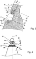
Nachfolgend wird die Erfindung anhand von Zeichnungen weiter beschrieben. Es zeigen schematisch:The invention will be further described with reference to drawings. They show schematically:
Diese Entladungslampe vom Kurzbogentyp
Bei der Anode
Bei dieser Entladungslampe vom Kurzbogentyp
Konkret ist der Bereich mit unterschiedlichen Durchmessern
- – Es sind beispielsweise sägezahnförmige konkav-
konvexe Teile 31A ,31B an zwei Stellen angeordnet, welche ausGruppen 32 konvexer Teile bestehen, die inAchsrichtung der Kathode 20 nebeneinander angeordnet sind, wobei - – im Querschnitt, welche die Mittelachse C der Kathode
20 einschließt, der Eckpunkt eines jeweiligen konvexen Teils33 von der Kantenlinie R des sich verjüngenden Teils21 aus gesehen auf deren Innenseite positioniert ist, und - – die Mantelkurve L, welche die jeweiligen Eckpunkte verbindet, bezüglich der Mittellinie C der Kathode
20 konvex ist. - – Es ist
ein glatter Teil 35 angeordnet, dessen eines Ende angrenzt an einen konvexen Teil33A am hinteren Ende der Anordnung der konvexen Teile33 des konkav-konvexen Teils 31A von der Spitze her gesehen, dessen anderes Ende zugleich an einen konvexen Teil33B am äußersten vorderen Ende der Anordnung der konvexen Teile33 des konkav-konvexen Teils 31B auf der Seite des hinteren Endes angrenzt und dessen Oberfläche im Wesentlichen glatt ist.
- - For example, they are sawtooth-shaped concave-
convex parts 31A .31B arranged in two places, which are made up ofgroups 32 Convex parts exist in the axial direction of thecathode 20 are arranged next to each other, wherein - - In cross section, which the central axis C of the
cathode 20 includes, the vertex of a respectiveconvex part 33 from the edge line R of thetapered part 21 Seen from the inside, and - - The envelope curve L, which connects the respective vertices, with respect to the center line C of the
cathode 20 is convex. - - It's a
smooth part 35 arranged one end adjacent to aconvex part 33A at the rear end of the arrangement of theconvex parts 33 of the concavo-convex part 31A seen from the top, the other end at the same time to aconvex part 33B at the extreme front end of the arrangement of theconvex parts 33 of the concavo-convex part 31B on the side of the rear end and whose surface is substantially smooth.
Der Bereich mit unterschiedlichen Durchmessern
Der Bereich mit unterschiedlichen Durchmessern
Man bildet an einer vorgegebenen Stelle in dem sich verjüngenden Teil
Die Tiefe d1 des glatten Teils
Es ist vorteilhaft, dass die Stelle, an welcher der Bereich mit unterschiedlichen Durchmessern
Nachfolgend werden die Zahlenwerte bei der Entladungslampe vom Kurzbogentyp
Es liegen:
- – der maximale Außendurchmesser der Leuchtröhre
11 bei 45 mm bis 300 mm; - – das Innenvolumen der Leuchtröhre
11 bei 40 cm3 bis 16000 cm3; - – der Abstand zwischen der Kathode
20 und derAnode 15 bei 3.5mm bis 50 mm; - – die Gesamtlänge (Länge in der Achsrichtung) des sich verjüngenden Teils
21 der Kathode 20 bei 3mm bis 55 mm; - – der Spitzenwinkel des sich verjüngenden Teils
21 der Kathode20 (Verjüngungswinkel θ) bei 30 bis 80°; - – die Gesamtlänge des Rumpfteils
22 der Kathode 20 bei 1 mm bis 100 mm; - – der Durchmesser des Rumpfteils
22 der Kathode 20 bis 5mm bis 30 mm; - – eine Tiefe d1 des glatten Teils
35 , welcher den Bereich mit unterschiedlichen Durchmessern30 bildet, ausgehend von der Oberfläche des sich verjüngenden Teils21 , bei 0.3 mm bis 3 mm; - – eine Breite W1 des glatten Teils
35 , welcher den Bereich mit unterschiedlichen Durchmessern30 bildet, (Länge in der Achsrichtung entlang der Oberfläche des sich verjüngenden Teils21 ) bei 0.3mm bis 15 mm; - – eine Tiefe d2 der konkaven Teile
34 ,34 der konkav-konvexen Teile 31A ,31B , welche den Bereich mit unterschiedlichen Durchmessern30 bilden, bei 0.2 mm bis 2 mm; - – Breiten W2, W2 der konkav-
konvexen Teile 31A ,31B , welche den Bereich mit unterschiedlichen Durchmessern30 bilden, bei 0.3mm bis 10 mm; - – die Anzahl der konvexen Teile
33 bei den konkav-konvexen Teile 31A ,31B bei größer/gleich 3 und - – der Abstand zwischen den Eckpunkten der benachbarten konvexen Teile
33 bei 0.1 mm bis 0.4 mm.
- - the maximum outside diameter of the
arc tube 11 at 45 mm to 300 mm; - - the internal volume of the
arc tube 11 at 40 cm 3 to 16000 cm 3 ; - - the distance between the
cathode 20 and theanode 15 at 3.5 mm to 50 mm; - The total length (length in the axial direction) of the
tapered part 21 thecathode 20 at 3 mm to 55 mm; - - the point angle of the
tapered part 21 the cathode20 (Taper angle θ) at 30 to 80 °; - - the total length of the
body part 22 thecathode 20 at 1 mm to 100 mm; - - the diameter of the
body part 22 thecathode 20 up to 5 mm to 30 mm; - A depth d1 of the
smooth part 35 , which is the area withdifferent diameters 30 forms, starting from the surface of thetapered part 21 at 0.3 mm to 3 mm; - A width W1 of the
smooth part 35 , which is the area withdifferent diameters 30 forms (length in the axial direction along the surface of the tapered part21 ) at 0.3 mm to 15 mm; - A depth d2 of the
concave parts 34 .34 the concave-convex parts 31A .31B showing the area withdifferent diameters 30 form, at 0.2 mm to 2 mm; - Widths W2, W2 of the concavo-
convex parts 31A .31B showing the area withdifferent diameters 30 form, at 0.3 mm to 10 mm; - - the number of
convex parts 33 at the concave-convex parts 31A .31B at greater than or equal to 3 and - - The distance between the vertices of the adjacent
convex parts 33 at 0.1 mm to 0.4 mm.
Im Fall einer Verwendung als Lichtquelle im Gebiet der Projektion wird die Einfüllmenge des Edelgases auf einen Druck in einem Bereich von 0.1 MPa bis 4 MPa bei einer Bezugstemperatur von 300 K festgelegt. Im Fall einer Verwendung als Lichtquelle im Gebiet der Halbleiter-Herstellung wird die Einfüllmenge des Edelgases auf einen Druck in einem Bereich von 0.01 MPa bis 1 MPa bei einer Bezugstemperatur von 300 K festgelegt, und die Einfüllmenge des Quecksilbers liegt bei 1 mg/cm3 bis 100 mg/cm3.In the case of use as a light source in the field of projection, the filling amount of the rare gas is set to a pressure in a range of 0.1 MPa to 4 MPa at a reference temperature of 300 K. In the case of use as a light source in the field of semiconductor manufacturing, the filling amount of the rare gas is set to a pressure in a range of 0.01 MPa to 1 MPa at a reference temperature of 300 K, and the mercury charging amount is 1 mg / cm 3 to 100 mg / cm 3 .
Bei der Entladungslampe vom Kurzbogentyp
Das heißt, man hat eine Anordnung, bei welcher sich der Konzentrationsgrad des elektrischen Feldes der konkav-konvexen Teile
Wenn bei der Kathode
Man kann die vorstehend beschriebene Wirkung ferner durch die Anordnung noch zuverlässiger erhalten, bei welcher in dem Bereich mit unterschiedlichen Durchmessern
Vorstehend wurde zwar ein Ausführungsbeispiel der erfindungsgemäßen Lampeneinheit beschrieben. Die Erfindung ist jedoch nicht auf die vorstehend beschriebene Ausführung beschränkt, sondern man kann ihr verschiedene Änderungen hinzufügen.Although an embodiment of the lamp unit according to the invention has been described above. However, the invention is not limited to the embodiment described above, but various changes can be added thereto.
Die Form der konkav-konvexen Teile, welche den Bereich mit unterschiedlichen Durchmessern bei der Kathode bilden, sowie die Form des glatten Teils sind beispielsweise nicht speziell beschränkt, sondern man kann die konkav-konvexen Teile
Es ist ausreichend, wenn der glatte Teil, welcher den Bereich mit unterschiedlichen Durchmessern bildet, einen Bereich darstellt, dessen Feldstärke zur Feldstärke der mit den konkav-konvexen Teilen versehenen Bereichen diskontinuierlich ist. Man kann in dem glatten Teil beispielsweise auch ringförmige Rillen oder Vorsprünge, welche sich in der Umfangsrichtung erstrecken, bilden.It is sufficient if the smooth part constituting the region of different diameters represents a region whose field strength is discontinuous to the field strength of the regions provided with the concavo-convex parts. For example, annular grooves or protrusions extending in the circumferential direction may also be formed in the smooth part.
Es ist nicht erforderlich, dass die konkav-konvexen Teile, welche den Bereich mit unterschiedlichen Durchmessern bilden, an zwei Stellen gebildet sind. Es ist ausreichend, wenn sie zumindest an die Spitzenseite der Kathode in dem glatten Teil angrenzen.It is not necessary that the concavo-convex parts constituting the area of different diameters are formed in two places. It is sufficient if they are at least adjacent to the tip side of the cathode in the smooth part.
Nachfolgend werden Versuchsbeispiele beschrieben, welche für eine Bestätigung der Wirkung der Erfindung durchgeführt wurden. Die Erfindung ist jedoch nicht darauf beschränkt.Hereinafter, experimental examples which have been carried out for confirming the effect of the invention will be described. However, the invention is not limited thereto.
Herstellungsbeispiel 1 einer Lampe vom KurzbogentypProduction example 1 of a lamp of the short arc type
Entsprechend der in
Leuchtröhre (
Innenvolumen: 600 cm3
Kathode (
Gesamtlänge (Länge in der Achsrichtung) des sich verjüngenden Teils (
Spitzenwinkel (θ) des sich verjüngenden Teils: 60°
Gesamtlänge des Rumpfteils (
Durchmesser des Rumpfteils: 20 mm
Anordnung des Bereichs mit unterschiedlichen Durchmessern (
Position, an welcher der konkav-konvexe Teil (
Oberflächenform des glatten Teils, welcher den Bereich mit unterschiedlichen Durchmessern bildet: flach
Tiefe (d1) des glatten Teils ausgehend von der Oberfläche des sich verjüngenden Teils: 0.5 mm
Breite (W1) des glatten Teils: 1.7 mm
Form des jeweiligen konkav-konvexen Teils, welcher den Bereich mit unterschiedlichen Durchmessern bildet: ringförmige Rille mit einem V-förmigen Querschnitt
Tiefe (d2) des jeweiligen konkaven Teils (
Breite (W2) des jeweiliger konkav-konvexen Teils: 1.2 mm
Anzahl der konvexen Teile (
Abstand zwischen den Eckpunkten der benachbarten konvexen Teile (
Anode (
Gesamtlänge: 50 mm
Abstand zwischen der Kathode (
Eingefülltes Gas: Xenongas
Einfüllgasdruck: 0.90 × 10⁵ Pa
Quecksilbermenge: 20 mg/cm3
Eingangsleistung: 10 kW
Lampenspannung im stabilen Zustand (zu Anfang): 90 VAccording to the in
Light tube (
Inner volume: 600 cm 3
Cathode (
Total length (length in the axial direction) of the tapered part (
Point angle (θ) of the tapered part: 60 °
Total length of the body part (
Diameter of the fuselage: 20 mm
Arrangement of the area with different diameters (
Position at which the concavo-convex part (
Surface shape of the smooth part, which forms the area with different diameters: flat
Depth (d1) of the smooth part from the surface of the tapered part: 0.5 mm
Width (W1) of the smooth part: 1.7 mm
Shape of the respective concavo-convex portion forming the range of different diameters: annular groove having a V-shaped cross section
Depth (d2) of the respective concave part (
Width (W2) of the respective concavo-convex part: 1.2 mm
Number of convex parts (
Distance between the vertices of adjacent convex parts (
Anode (
Total length: 50 mm
Distance between the cathode (
Filled gas: Xenon gas
Filling gas pressure: 0.90 × 10 5 Pa
Amount of mercury: 20 mg / cm 3
Input power: 10 kW
Lamp voltage in stable state (at the beginning): 90 V
Herstellungsbeispiel 2 einer Lampe vom KurzbogentypProduction example 2 of a lamp of the short arc type
Eine erfindungsgemäße Entladungslampe vom Kurzbogentyp mit derselben Anordnung wie die Lampe A wurde hergestellt, abgesehen von der Verwendung einer Kathode mit einer nachstehend beschriebenen Anordnung (siehe
Anordnung des Bereichs mit unterschiedlichen Durchmessern (
Position, an welcher der konkav-konvexe Teil (
Oberflächenform des glatten Teils, welcher den Bereich mit unterschiedlichen Durchmessern bildet: kugelflächig
Maximale Tiefe des glatten Teils ausgehend von der Oberfläche des sich verjüngenden Teils: 0.6 mm
Breite (W3) des glatten Teils: 0.6 mm
Form der konkav-konvexen Teile, welche den Bereich mit unterschiedlichen Durchmessern bilden: spiralförmige Rillen mit einem V-förmigen Querschnitt
Anzahl der konvexen Teile (
Abstand zwischen den Eckpunkten der benachbarten konvexen Teile bei den konkav-konvexen Teilen: 0.15 mm
Tiefe des jeweiligen konkaven Teils (
Breite (W4) des jeweiligen konkav-konvexen Teils: 0.9 mmA short arc type discharge lamp according to the present invention having the same arrangement as the lamp A was manufactured except for using a cathode having an arrangement described below (see FIG
Arrangement of the area with different diameters (
Position at which the concavo-convex part (
Surface shape of the smooth part, which forms the area with different diameters: spherical surface
Maximum depth of the smooth part from the surface of the tapered part: 0.6 mm
Width (W3) of the smooth part: 0.6 mm
Shape of the concavo-convex parts forming the area of different diameters: spiral grooves having a V-shaped cross section
Number of convex parts (
Distance between the vertices of the adjacent convex parts in the concavo-convex parts: 0.15 mm
Depth of the respective concave part (
Width (W4) of the respective concavo-convex part: 0.9 mm
Herstellungsbeispiel 3 einer Lampe vom KurzbogentypProduction example 3 of a lamp of the short arc type
Eine Entladungslampe vom Kurzbogentyp zum Vergleichszweck mit derselben Anordnung wie die Lampe A, abgesehen von der Verwendung einer Kathode mit der in
Form des konkaven Teils (
Position, an welcher der konkave Teil gebildet ist: eine Stelle, welche sich bezüglich der Achsrichtung um 2 mm hinter der Spitzenfläche der Kathode befindet.
Tiefe des konkaven Teils: 0.5 mm
Breite des konkaven Teils: 0.15 mmA discharge lamp of the short arc type for the purpose of comparison with the same arrangement as the lamp A, except for the use of a cathode with the in
Shape of the concave part (
Position at which the concave part is formed: a position which is 2 mm behind the tip surface of the cathode with respect to the axial direction.
Depth of the concave part: 0.5 mm
Width of the concave part: 0.15 mm
Herstellungsbeispiel 4 einer Lampe vom Kurzbogentyp Production Example 4 of a Short-arc Type Lamp
Eine Entladungslampe vom Kurzbogentyp zum Vergleichszweck mit derselben Anordnung wie die Lampe A wurde hergestellt, abgesehen von der Verwendung einer Kathode für die bei dem vorstehend beschriebenen Herstellungsbeispiel 1 erhaltene Lampe A mit einer Anordnung, bei welcher kein Bereich mit unterschiedlichen Durchmessern angeordnet ist. Nachfolgend wird diese Entladungslampe vom Kurzbogentyp ”Lampe D” genannt. Die Abmessung des sich verjüngenden Teils sowie die Abmessung des Rumpfteils der Kathode bei dieser Lampe D sind mit der Größe der Lampe A identisch.A discharge lamp of the short arc type for comparison purpose having the same arrangement as the lamp A was prepared except for using a cathode for the lamp A obtained in the above-described Production Example 1 with an arrangement in which no area of different diameters is arranged. Hereinafter, this discharge lamp is called the short arc type "lamp D". The dimension of the tapered portion and the dimension of the body portion of the cathode in this lamp D are identical to the size of the lamp A.
Versuchsbeispielexperimental example
Ein Versuch, bei welchem man die vorstehend beschriebenen Lampen A bis D jeweils sechs Stunden lang ununterbrochen betreibt und sie danach zwei Stunden lang ausschaltet, wurde 150-mal wiederholt. Zu einem Zeitpunkt, zu welchem dieser Versuch zum 50. Mal durchgeführt wurde, zu einem Zeitpunkt, zu welchem dieser Versuch zum 100. Mal durchgeführt wurde, sowie zu einem Zeitpunkt, zu welchem dieser Versuch zum 150. Mal durchgeführt wurde, wurde die Entstehungshäufigkeit des Schwankungsphänomens des Lichtbogens beim Starten der Lampe visuell bestätigt. Zugleich hat man zu einem Zeitpunkt, zu welchem dieser Versuch zum 50. Mal durchgeführt wurde, zu einem Zeitpunkt, zu welchem dieser Versuch zum 100. Mal durchgeführt wurde, sowie zu einem Zeitpunkt, zu welchem dieser Versuch zum 150. Mal durchgeführt wurde, visuell bestätigt, ob eine Entglasung der Leuchtröhre entstanden ist oder nicht. Nachfolgend wird anhand von Tabelle 1 das Ergebnis gezeigt. Hierbei soll man unter dem Begriff ”Entstehungshäufigkeit des Schwankungsphänomens des Lichtbogens” eine gezählte Häufigkeit verstehen, mit welcher sich beim Starten der Lampe der Startpunkt des Lichtbogens von der Spitzenfläche der Kathode zur Oberflächenposition des Rumpfteils der Kathode bewegt hat (beispielsweise eine Häufigkeit, mit welcher der in
Wie vorstehend beschrieben wurde, hat man für die erfindungsgemäßen Lampen A und B folgendes bestätigt:
- – Das Entstehen des Schwankungsphänomens des Lichtbogens wird mit Sicherheit verhindert.
- – Das Entstehen einer Entglasung der Leuchtröhre infolge des Schwankungsphänomens des Lichtbogens wird mit Sicherheit verhindert.
- – Man kann deshalb eine gewünschte Leistungsfähigkeit der Lampe über eine lange Zeit erhalten.
- - The emergence of the fluctuation phenomenon of the arc is prevented with certainty.
- - The emergence of devitrification of the arc tube due to the fluctuation phenomenon of the arc is prevented with certainty.
- It is therefore possible to obtain a desired efficiency of the lamp for a long time.
Bei den Lampen C und D zum Vergleichszweck wurde dagegen folgendes bestätigt:
- – Die Entstehungshäufigkeit des Schwankungsphänomens des Lichtbogens erhöht sich entsprechend einer Zunahme de Häufigkeit des Ein- oder Ausschaltbetriebs der Lampe (Versuchshäufigkeit).
- – Eine Entglasung der Leuchtröhre entsteht bei der Lampe C zum Zeitpunkt nach 150-maliger Versuchsdurchführung.
- – Eine Entglasung der Leuchtröhre entsteht bei der Lampe D zum Zeitpunkt nach 100-maliger Versuchsdurchführung.
- - The frequency of occurrence of the fluctuation phenomenon of the arc increases in accordance with an increase de frequency of on or off operation of the lamp (experimental frequency).
- Devitrification of the arc tube occurs at lamp C at the time after 150 experiments.
- Devitrification of the arc tube occurs with the lamp D at the time after 100 experiments.
Claims (6)
Applications Claiming Priority (2)
| Application Number | Priority Date | Filing Date | Title |
|---|---|---|---|
| JP2004/057757 | 2004-03-02 | ||
| JP2004057757A JP4714418B2 (en) | 2004-03-02 | 2004-03-02 | Discharge lamp |
Publications (2)
| Publication Number | Publication Date |
|---|---|
| DE102005007767A1 DE102005007767A1 (en) | 2005-09-22 |
| DE102005007767B4 true DE102005007767B4 (en) | 2012-09-27 |
Family
ID=34879835
Family Applications (1)
| Application Number | Title | Priority Date | Filing Date |
|---|---|---|---|
| DE102005007767A Active DE102005007767B4 (en) | 2004-03-02 | 2005-02-19 | Discharge lamp with a specially shaped cathode to prevent the fluctuation phenomenon of the arc |
Country Status (6)
| Country | Link |
|---|---|
| US (1) | US7759872B2 (en) |
| JP (1) | JP4714418B2 (en) |
| KR (1) | KR100764385B1 (en) |
| CN (1) | CN100550276C (en) |
| DE (1) | DE102005007767B4 (en) |
| TW (1) | TW200531120A (en) |
Families Citing this family (14)
| Publication number | Priority date | Publication date | Assignee | Title |
|---|---|---|---|---|
| US7652430B1 (en) * | 2005-07-11 | 2010-01-26 | Kla-Tencor Technologies Corporation | Broadband plasma light sources with cone-shaped electrode for substrate processing |
| JP4830638B2 (en) * | 2006-05-29 | 2011-12-07 | ウシオ電機株式会社 | High pressure discharge lamp |
| WO2008055550A1 (en) * | 2006-11-10 | 2008-05-15 | Osram Gesellschaft mit beschränkter Haftung | Electrode, in particular cathode, for a discharge lamp |
| DE102006061375B4 (en) | 2006-12-22 | 2019-01-03 | Osram Gmbh | Mercury high-pressure discharge lamp with an anode containing tungsten and potassium, which has a grain count greater than 200 grains per mm 2 and a density greater than 19.05 g / cm 3 |
| JP4993478B2 (en) * | 2007-03-23 | 2012-08-08 | 株式会社オーク製作所 | Discharge lamp and method of manufacturing electrode thereof |
| JP4868036B2 (en) * | 2009-07-31 | 2012-02-01 | ウシオ電機株式会社 | High pressure discharge lamp |
| JP5369360B2 (en) * | 2009-09-11 | 2013-12-18 | 岩崎電気株式会社 | Light source electrode |
| TWM403094U (en) * | 2010-05-26 | 2011-05-01 | Arclite Optronics Corp | Structure of gas discharge lamp |
| JP5056916B2 (en) * | 2010-07-12 | 2012-10-24 | ウシオ電機株式会社 | High pressure discharge lamp |
| JP5664602B2 (en) * | 2012-07-10 | 2015-02-04 | ウシオ電機株式会社 | Short arc type mercury lamp |
| JP6633826B2 (en) * | 2014-09-24 | 2020-01-22 | 株式会社オーク製作所 | Discharge lamp |
| JP6647678B2 (en) * | 2015-12-02 | 2020-02-14 | 岩崎電気株式会社 | Short arc discharge lamp |
| DE102018206770A1 (en) * | 2018-05-02 | 2019-11-07 | Osram Gmbh | Electrode for a discharge lamp, discharge lamp and method for producing an electrode |
| JP2024012866A (en) * | 2022-07-19 | 2024-01-31 | ウシオ電機株式会社 | Xenon lamp for projectors |
Citations (5)
| Publication number | Priority date | Publication date | Assignee | Title |
|---|---|---|---|---|
| GB2107921A (en) * | 1981-10-15 | 1983-05-05 | Emi Plc Thorn | Discharge lamp electrode |
| DE20005534U1 (en) * | 2000-03-29 | 2000-06-21 | Patent Treuhand Ges Fuer Elektrische Gluehlampen Mbh | Short arc lamp |
| US20030042853A1 (en) * | 2001-08-30 | 2003-03-06 | Ushiodenki Kabushiki Kaisha | Mercury discharge lamp of the short arc type |
| JP2003223865A (en) * | 2002-01-31 | 2003-08-08 | Ushio Inc | Positive electrode for discharge lamp and short arc discharge lamp |
| JP2003257363A (en) * | 2002-03-01 | 2003-09-12 | Ushio Inc | Short arc type discharge lamp |
Family Cites Families (4)
| Publication number | Priority date | Publication date | Assignee | Title |
|---|---|---|---|---|
| JPH09231946A (en) * | 1996-02-23 | 1997-09-05 | Ushio Inc | Short arc electric discharge lamp |
| JPH11102662A (en) * | 1997-09-25 | 1999-04-13 | Ushio Inc | Short arc type discharge lamp |
| DE19749908A1 (en) * | 1997-11-11 | 1999-05-12 | Patent Treuhand Ges Fuer Elektrische Gluehlampen Mbh | Electrode component for discharge lamps |
| JP4512968B2 (en) * | 2000-08-03 | 2010-07-28 | ウシオ電機株式会社 | Short arc type high pressure discharge lamp |
-
2004
- 2004-03-02 JP JP2004057757A patent/JP4714418B2/en not_active Expired - Lifetime
- 2004-11-11 TW TW093134484A patent/TW200531120A/en unknown
-
2005
- 2005-01-24 KR KR1020050006326A patent/KR100764385B1/en active IP Right Grant
- 2005-02-19 DE DE102005007767A patent/DE102005007767B4/en active Active
- 2005-03-01 US US11/067,951 patent/US7759872B2/en active Active
- 2005-03-02 CN CNB2005100531124A patent/CN100550276C/en active Active
Patent Citations (5)
| Publication number | Priority date | Publication date | Assignee | Title |
|---|---|---|---|---|
| GB2107921A (en) * | 1981-10-15 | 1983-05-05 | Emi Plc Thorn | Discharge lamp electrode |
| DE20005534U1 (en) * | 2000-03-29 | 2000-06-21 | Patent Treuhand Ges Fuer Elektrische Gluehlampen Mbh | Short arc lamp |
| US20030042853A1 (en) * | 2001-08-30 | 2003-03-06 | Ushiodenki Kabushiki Kaisha | Mercury discharge lamp of the short arc type |
| JP2003223865A (en) * | 2002-01-31 | 2003-08-08 | Ushio Inc | Positive electrode for discharge lamp and short arc discharge lamp |
| JP2003257363A (en) * | 2002-03-01 | 2003-09-12 | Ushio Inc | Short arc type discharge lamp |
Also Published As
| Publication number | Publication date |
|---|---|
| US20050194904A1 (en) | 2005-09-08 |
| DE102005007767A1 (en) | 2005-09-22 |
| JP4714418B2 (en) | 2011-06-29 |
| TW200531120A (en) | 2005-09-16 |
| TWI320576B (en) | 2010-02-11 |
| CN100550276C (en) | 2009-10-14 |
| JP2005251471A (en) | 2005-09-15 |
| CN1664982A (en) | 2005-09-07 |
| US7759872B2 (en) | 2010-07-20 |
| KR20050088932A (en) | 2005-09-07 |
| KR100764385B1 (en) | 2007-10-08 |
Similar Documents
| Publication | Publication Date | Title |
|---|---|---|
| DE102005007767B4 (en) | Discharge lamp with a specially shaped cathode to prevent the fluctuation phenomenon of the arc | |
| EP1481418B1 (en) | Short arc high-pressure discharge lamp- | |
| DE69822014T2 (en) | Method for producing a high-pressure discharge lamp | |
| EP0451647B1 (en) | High-pressure discharge lamp and method for its manufacture | |
| DE60126704T2 (en) | High pressure discharge lamp with long life | |
| DE102007013583A1 (en) | High pressure discharge lamp for e.g. projector or utilization of digital light processing technology as source of light, has bulb and oppositely arranged anode and cathode, which has tungsten with thorium dioxide | |
| DE3616330A1 (en) | SHORT BOW LAMP | |
| DD245081A5 (en) | COMPACT MERCURY LOW-PRESSURE DAMPING DISCHARGE LAMP AND A METHOD OF MANUFACTURING THEREOF | |
| DE19747803C2 (en) | Metal halide lamp, this comprehensive lighting device and use of the latter | |
| DE4031117A1 (en) | High pressure discharge lamp and method for producing the lamp | |
| DE102006061375B4 (en) | Mercury high-pressure discharge lamp with an anode containing tungsten and potassium, which has a grain count greater than 200 grains per mm 2 and a density greater than 19.05 g / cm 3 | |
| DE10305339B4 (en) | Short-arc discharge lamp | |
| DE102004053094B4 (en) | High-pressure discharge lamp | |
| EP0479088B1 (en) | High pressure discharge lamp and method for producing the same | |
| EP0383108B1 (en) | High-pressure discharge lamp for operation with an alternating current | |
| DE60221221T2 (en) | Super high-pressure discharge lamp of the short arc type | |
| DE2223084A1 (en) | Arc lamp and method of assembling it | |
| DE102013107327B4 (en) | Short arc type mercury lamp containing Kr and whose anode has a conical end portion with a flat front end surface | |
| DE102012005373B4 (en) | Short-arc discharge lamp with spherical or oval outer shape of the fluorescent tube part and a spiral part at the tip end of an electrode | |
| DE102011016363B4 (en) | SHORT-DISCHARGE DISCHARGE LAMP WITH CATHODE, IN WHICH AN EMITTER MATERIAL IS EITHER EQUALLY ORGANIC OR ELLIPTICALLY CONSTRUCTED | |
| DE60038414T2 (en) | discharge lamp | |
| DE102010034661B4 (en) | Short arc discharge lamp with longitudinal opening in the anode, on whose inner surface microcracks are formed | |
| DE60224041T2 (en) | FLUORESCENT LAMP AND METHOD OF MANUFACTURING | |
| DE102010024240A1 (en) | Anode for use in fluorescent tube in short arc-discharge lamp utilized as light source for exposure device that forms little switching circuit pattern, has boundary area distanced from anode middle axis in radial outward aligned manner | |
| DE102011105403A1 (en) | High pressure discharge lamp |
Legal Events
| Date | Code | Title | Description |
|---|---|---|---|
| 8110 | Request for examination paragraph 44 | ||
| R016 | Response to examination communication | ||
| R016 | Response to examination communication | ||
| R018 | Grant decision by examination section/examining division | ||
| R020 | Patent grant now final |
Effective date: 20121228 |
|
| R082 | Change of representative |
Representative=s name: MAIWALD GMBH, DE |