DE10162656B4 - Servo-pneumatic modular welding gun - Google Patents

Servo-pneumatic modular welding gun Download PDF

Info

Publication number
DE10162656B4
DE10162656B4 DE10162656A DE10162656A DE10162656B4 DE 10162656 B4 DE10162656 B4 DE 10162656B4 DE 10162656 A DE10162656 A DE 10162656A DE 10162656 A DE10162656 A DE 10162656A DE 10162656 B4 DE10162656 B4 DE 10162656B4
Authority
DE
Germany
Prior art keywords
welding
pneumatic
servo
control device
nxx
Prior art date
Legal status (The legal status is an assumption and is not a legal conclusion. Google has not performed a legal analysis and makes no representation as to the accuracy of the status listed.)
Revoked
Application number
DE10162656A
Other languages
German (de)
Other versions
DE10162656A1 (en
Inventor
William E. Canton Janssens
Thomas J. Birmingham Cusumano
Tarek El-Sawaf
Michael Zona
Louis Ariosto
Current Assignee (The listed assignees may be inaccurate. Google has not performed a legal analysis and makes no representation or warranty as to the accuracy of the list.)
Festo SE and Co KG
Original Assignee
Festo SE and Co KG
Priority date (The priority date is an assumption and is not a legal conclusion. Google has not performed a legal analysis and makes no representation as to the accuracy of the date listed.)
Filing date
Publication date
Family has litigation
First worldwide family litigation filed litigation Critical https://patents.darts-ip.com/?family=25034980&utm_source=google_patent&utm_medium=platform_link&utm_campaign=public_patent_search&patent=DE10162656(B4) "Global patent litigation dataset” by Darts-ip is licensed under a Creative Commons Attribution 4.0 International License.
Application filed by Festo SE and Co KG filed Critical Festo SE and Co KG
Publication of DE10162656A1 publication Critical patent/DE10162656A1/en
Application granted granted Critical
Publication of DE10162656B4 publication Critical patent/DE10162656B4/en
Anticipated expiration legal-status Critical
Revoked legal-status Critical Current

Links

Classifications

    • BPERFORMING OPERATIONS; TRANSPORTING
    • B23MACHINE TOOLS; METAL-WORKING NOT OTHERWISE PROVIDED FOR
    • B23KSOLDERING OR UNSOLDERING; WELDING; CLADDING OR PLATING BY SOLDERING OR WELDING; CUTTING BY APPLYING HEAT LOCALLY, e.g. FLAME CUTTING; WORKING BY LASER BEAM
    • B23K11/00Resistance welding; Severing by resistance heating
    • B23K11/30Features relating to electrodes
    • B23K11/31Electrode holders and actuating devices therefor
    • B23K11/314Spot welding guns, e.g. mounted on robots
    • BPERFORMING OPERATIONS; TRANSPORTING
    • B23MACHINE TOOLS; METAL-WORKING NOT OTHERWISE PROVIDED FOR
    • B23KSOLDERING OR UNSOLDERING; WELDING; CLADDING OR PLATING BY SOLDERING OR WELDING; CUTTING BY APPLYING HEAT LOCALLY, e.g. FLAME CUTTING; WORKING BY LASER BEAM
    • B23K11/00Resistance welding; Severing by resistance heating
    • B23K11/30Features relating to electrodes
    • B23K11/31Electrode holders and actuating devices therefor
    • B23K11/314Spot welding guns, e.g. mounted on robots
    • B23K11/315Spot welding guns, e.g. mounted on robots with one electrode moving on a linear path
    • BPERFORMING OPERATIONS; TRANSPORTING
    • B23MACHINE TOOLS; METAL-WORKING NOT OTHERWISE PROVIDED FOR
    • B23KSOLDERING OR UNSOLDERING; WELDING; CLADDING OR PLATING BY SOLDERING OR WELDING; CUTTING BY APPLYING HEAT LOCALLY, e.g. FLAME CUTTING; WORKING BY LASER BEAM
    • B23K11/00Resistance welding; Severing by resistance heating
    • B23K11/30Features relating to electrodes
    • B23K11/31Electrode holders and actuating devices therefor
    • B23K11/317Equalizing; Balancing devices for electrode holders

Landscapes

  • Engineering & Computer Science (AREA)
  • Mechanical Engineering (AREA)
  • Robotics (AREA)
  • Resistance Welding (AREA)

Abstract

Servo-pneumatische Punktschweißzange (10), welche aufweist:
ein Schweißzangen-Basismodul (12);
einen Pneumatikzylinder (16), der an das Basismodul (12) angekoppelt ist und einen beweglichen Kolben enthält mit einer ersten Schweißelektrode (30), die mit seinem äußeren Ende verbunden ist für eine Hin- und Herbewegung von einem ersten Ende des Zylinders (16);
einen Arm (14) mit einem ersten Ende, das an dem Schweißzangen-Basismodul (12) befestigt ist, und einem zweiten Ende, mit dem eine zweite Schweißelektrode (36) verbunden ist, wobei die zweite Schweißelektrode (36) axial ausgerichtet ist und zu der ersten Schweißelektrode (30) weist, wobei zwischen ihnen ein Spalt bestimmt wird; und
eine eingebaute programmierbare Steuerungsvorrichtung (88) mit einem Mikroprozessor, die eine frei programmierbare Positions- und Schweißdrucksteuerung für den zwischen der ersten und der zweiten Schweißelektrode (30, 36) angelegten Schweißdruck aufweist, und die mit dem Pneumatikzylinder (16) funktionell verbunden ist, zum Steuern der Bewegung der ersten Schweißelektrode (30) zu einer Vielzahl programmierbarer...
Servo-pneumatic spot welding gun (10), comprising:
a welding tongs base module (12);
a pneumatic cylinder (16) coupled to the base module (12) and including a movable piston having a first welding electrode (30) connected at its outer end for reciprocating movement from a first end of the cylinder (16) ;
an arm (14) having a first end attached to the welding gun base module (12) and a second end to which a second welding electrode (36) is connected, the second welding electrode (36) being axially aligned and closed the first welding electrode (30) points, between which a gap is determined; and
a built-in programmable controller (88) having a microprocessor having freely programmable position and welding pressure control for the welding pressure applied between the first and second welding electrodes (30, 36) and operatively connected to the pneumatic cylinder (16); Controlling the movement of the first welding electrode (30) to a plurality of programmable ...

Figure 00000001
Figure 00000001

Description

Gebiet der ErfindungField of the invention

Die vorliegende Erfindung bezieht sich allgemein auf Punktschweißzangen und insbesondere auf ein servo-pneumatisches modulares Schweißzangensystem mit einer frei programmierbaren Positions- und Drucksteuerung mit einer geschlossenen Schleife bzw. mit Rückkopplung. Die vorliegende Erfindung eignet sich gut für Schweißanwendungen bei einer Schnellmontagelinie insbesondere in der Automobilindustrie.The The present invention relates generally to spot welding guns and in particular to a servo-pneumatic modular welding gun system with a freely programmable position and pressure control with a closed loop or with feedback. The present Invention is well suited for welding applications in a quick assembly line, especially in the automotive industry.

Hintergrund der ErfindungBackground of the invention

Widerstands- oder Punktschweißen verbindet mittlere bzw. mittelstarke Bleche oder Strukturen durch Wärme, die durch den Widerstand gegenüber dem Fluß des elektrischen Stroms erzeugt wird. Die zu verschweissenden Metallstrukturen werden üblicherweise mit stabförmigen Elektroden zusammengeklemmt, wobei an entgegengesetzten Seiten Druck angelegt wird. Ein zwischen den Elektroden hindurchtretender elektrischer Strom trifft auf einen Widerstand, wenn er durch die Metallstrukturen fließt, wodurch Hitze erzeugt wird, die das Metall schmelzt und es zusammenschweißt.resistance or spot welding combines medium and medium strength sheets or structures by heat, the through the resistance the river of electric current is generated. The metal structures to be welded become common with rod-shaped Electrodes are clamped together, with pressure on opposite sides is created. A passing between the electrodes electrical Electricity encounters resistance when passing through the metal structures flows, generating heat that melts the metal and welds it together.

Herkömmliche Punktschweißzangen verwenden einen oder mehrere Pneumatikzylinder, um eine bewegbare Elektrode auszufahren und einzuziehen und um die Klemmkraft an den zu schwei ßenden Materialien anzulegen. Der Pneumatikzylinder bewegt die Elektrodenschweißspitze zu einer von mindestens drei bekannten Positionen. Diese Festanschlag-Positionen enthalten eine völlig eingezogene, eine völlig ausgefahrene und ein Mittelpunkt-Position. Nach dem Schweißen mit der Schweißspitze in ihrer völlig ausgefahrenen Position kehrt die Kolbenstange zu einer Mittelpunkt-Position anstatt ihrer vollständig eingezogenen Position zurück. Dies verringert die Zykluszeit zwischen den Schweißungen. Um diesen Auslegungsparameter zu erzielen, wird normalerweise ein Dreipositions-Pneumatikzylinder mit einer festgelegten Mittelpunkt-Position in der Punktschweißzange verwendet.conventional Spot welding guns Use one or more pneumatic cylinders to move one Extend and retract electrode and the clamping force to the too shy Create materials. The pneumatic cylinder moves the electrode welding tip to one of at least three known positions. These hard stop positions contain a completely fed, one completely extended and a midpoint position. After welding with the welding tip in her completely extended position, the piston rod returns to a midpoint position instead of her completely retracted position back. This reduces the cycle time between the welds. To achieve this design parameter is usually a Three-position pneumatic cylinder with a fixed center position in the spot welding gun used.

Üblicherweise diktiert die spezielle Schweißanwendung die Auslegung der Konfiguration der Schweißzange. Mit anderen Worten werden Schweißzangen üblicherweise speziell angefertigt, um der speziellen Schweißanwendung gerecht zu werden. Einige Betrachtungen müssen bei der speziellen Auslegung einer Schweißzange angesprochen werden. Die Auslegungsparameter enthalten den Spalt zwischen den Elektroden-Schweißspitzen, den Hub der beweglichen Elektrode, den Festpositionen der Elektroden-Schweißspitze und die Zykluszeit. So wird je nach den Schweißanwendungen eine speziell angefertigte Schweißzange um einen ausgewählten Dreipositions-Pneumatikzylinder ausgelegt. Somit können im Umfeld einer Montagelinie verschiedene unterschiedliche Konfigurationen von Schweißzangen zu irgendeiner Zeit in Betrieb sein. Der offensichtliche Nachteil speziell ausgelegter Schweißzangen ist das vollständige Fehlen der Standardisierung und Austauschbarkeit.Usually dictates the special welding application the design of the configuration of the welding gun. In other words Welding tongs are usually specially made to meet the specific welding application. Some considerations need be addressed in the special design of a welding gun. The design parameters include the gap between the electrode tips, the stroke of the movable electrode, the fixed positions of the electrode welding tip and the cycle time. Thus, depending on the welding applications a special made welding tongs around a selected one Three-position pneumatic cylinder designed. Thus, in the Environment of an assembly line different different configurations of welding tongs be in operation at any time. The obvious disadvantage specially designed welding guns is the whole Lack of standardization and interchangeability.

Wenn ein Schweißparameter in einem herkömmlichen Schweißzangensystem verändert wird, muß außerdem die Schweißzange gewöhnlicherweise auseinandergebaut und für den neuen Schweißparameter erneut ausgelegt werden. Wenn man z. B. die Schweißspitzen-Mittelpunkt-Position ändern möchte, muß man den bestehenden Zylinder durch einen neuen Pneumatikzylinder ersetzen. Während dieser Neuanpassung muß die Schweißzange aus der Montagelinie herausgenommen werden, was zu Produktions-Stillstandszeiten führt. Versuche zur Vermeidung des Nachteils bestehen unter anderem darin, Schweißzangen mit mehrfachen Pneumatikzylindern bereitzustellen. Allerdings ist ein Nachteil von Mehrfachzylinder-Schweißzangen die Gewichtszunahme und die Komplexität.If a welding parameter in a conventional Welding gun system changed must, must also welding gun usually disassembled and for the new welding parameter again be interpreted. If you z. B. would like to change the welding point-center position, you have the replace existing cylinder with a new pneumatic cylinder. While This adjustment must be the welding gun removed from the assembly line, resulting in production downtime. tries To avoid the disadvantage, among other things, there are welding tongs to provide with multiple pneumatic cylinders. However, that is a disadvantage of multiple cylinder welding guns is the increase in weight and the complexity.

Aus der EP 0 569 831 A2 ist eine Schweißzange mit einer externen Steuerungsvorrichtung und externen Ventilen bekannt, die keine programmierbare Steuerungsvorrichtung aufweist. Dies führt zu einer relativ unflexiblen und wenig kompakten Anordnung.From the EP 0 569 831 A2 a welding gun with an external control device and external valves is known, which has no programmable control device. This leads to a relatively inflexible and less compact arrangement.

Eine aus der EP 1 010 491 A2 bekannte Punktschweißzange weist zwar einen mittels eines Proportionalfluss-Steuerventils angesteuerten Pneumatikzylinder auf, jedoch sind keine Angaben für die spezielle Art der Steuerung enthalten.One from the EP 1 010 491 A2 Although known spot welding gun has a controlled by a proportional flow control valve pneumatic cylinder, but no information for the specific type of control are included.

Aus der US 5 478 982 A ist es zwar bekannt, zur Erfassung einer Kolbenposition ein lineares Potentiometer zu verwenden, jedoch bezieht sich der Gegenstand dieser Druckschrift nicht auf eine Punktschweißzange, sondern auf eine Vorrichtung zum Verschweißen von elektrischen Drähten.From the US 5,478,982 A. Although it is known to use a linear potentiometer to detect a piston position, however, the subject of this document does not refer to a spot welding gun, but to a device for welding electrical wires.

Aus der DE 32 06 432 C2 ist ein Schutzmantel zur Verhinderung des Anhaftens von Schweißspritzern auf einer Kolbenstange eines Arbeitszylinders an Schweißvorrichtungen bekannt, wobei der Pneumatikzylinder mit einem Schaberring ausgestattet ist. Im Hinblick auf eine Steuerung einer Punktschweißzange ist dieser Druckschrift nichts zu entnehmen.From the DE 32 06 432 C2 For example, there is known a protective jacket for preventing the adhesion of welding spatters on a piston rod of a working cylinder to welding apparatus, the pneumatic cylinder being provided with a scraper ring. With regard to a control of a spot welding gun this document is not apparent.

Es ist daher eine Aufgabe der Erfindung, eine Schweißzangen-Konfiguration mit einer standardmäßigen Auslegung bereitzustellen, die ohne weiteres mit anderen Schweißzangen ausgetauscht werden kann und die frei programmierbar ist, um eine beliebige Schweißspitzen-Positionierung und/oder einen beliebigen Druck zu erzeugen.It It is therefore an object of the invention to provide a welding tongs configuration with a standard design to provide that readily with other welding tongs can be exchanged and which is freely programmable to a any welding tip positioning and / or to generate any pressure.

Zusammenfassung der ErfindungSummary of the invention

Die vorliegende Erfindung betrifft eine servo-pneumatische Punktschweißzange mit den Merkmalen des Anspruchs 1.The The present invention relates to a servo-pneumatic spot welding gun with the features of claim 1.

Der Pneumatikzylinder enthält einen internen Positionscodierer zum Erfassen einer Kolbenposition und Übertragen der Kolbenposition-Information zu der Steuerungsvorrichtung, um die Bewegung des Kolbens durch ein Proportional-Strömungssteuerungsventil und einen Proportional-Druckregler zu steuern. Vorzugsweise ist der interne Positionscodierer ein lineares Potentiometer, das innerhalb der Kolbenstange des Pneumatikzylinders eingepaßt ist, um die Aussparung und Einziehung der Kolbenstange genau zu bestimmen.Of the Pneumatic cylinder contains an internal position encoder for detecting a piston position and transmitting the piston position information to the control device to the movement of the piston through a proportional flow control valve and a proportional pressure regulator to control. Preferably, the internal position encoder is a linear one Potentiometer inside the piston rod of the pneumatic cylinder fitted is accurate to the recess and retraction of the piston rod determine.

Die Schleifen-Positionssteuerung bzw. rückgekoppelte Positionssteuerung ermöglicht die Verwendung eines standardmäßigen Pneumatikzylinders mit bekanntem Hub und bekannter Zylinderbohrung. Somit ist die Schweißzange für eine lösbare Anbringung des Pneumatikzylinders und des Kanonenarms ausgelegt, wodurch der Pneumatikzylinder und der Kanonenarm mit anderen Pneumatikzylindern und Kanonenarmen ausgetauscht werden kann. Zusätzlich werden die Schweißzangen- Basismodulkomponenten aus hochfestem maschinell bearbeitetem Aluminium gefertigt, um das Gewicht zu verringern.The Loop position control or feedback position control allows the use of a standard pneumatic cylinder with known stroke and known cylinder bore. Thus, the welding gun is for a detachable attachment designed the pneumatic cylinder and the gun arm, whereby the Pneumatic cylinder and the gun arm with other pneumatic cylinders and gun arms can be exchanged. In addition, the welding tongs base module components become Made of high strength machined aluminum to make the Reduce weight.

Zum Steuern der Positon einer Punktschweißzangen-Schweißspitze wird eine Sequenz aus einer Vielzahl von Binärbit-Positionssequenzen, die einer unterschiedlichen Schweißspitzen-Position entsprechen, in einer Steuerungsvorrichtung eingegeben, welche die eingegebene Sequenz mit der durch einen interenen Positionscodierer erfaßten tatsächlichen Position der Schweißspitze vergleicht. Auf der Grundlage des Vergleiches aktiviert die Steuerungsvorrichtung ein Steuerungsventil eines Pneumatikzylinders, um die Schweißspitze auszufahren oder einzuziehen. Vorzugsweise umfaßt die Bitsequenz vier binäre Bits, die 16 mögliche Schweißspitzen-Orte darstellen.To the Controlling the position of a spot welding gun welding tip becomes a sequence a plurality of binary bit position sequences, which correspond to a different welding point position, entered in a control device which the entered Sequence with the detected by an internal position encoder actual Position of the welding tip compares. Based on the comparison, the control device activates a control valve of a pneumatic cylinder to the welding tip extend or retract. Preferably, the bit sequence comprises four binary bits, the 16 possible perspiration places represent.

Durch Manipulieren der Bitsequenzen und in Abhängigkeit von den eingegebenen Adressen der Steuerungsvorrichtung können andere Schweißparameter wie z. B. Schweißdruck, Ausgleichsdruck und Spitzendämpfung gesteuert werden. So enthält z. B. ein Verfahren zum Steuern des Schweißdruckes an der Schweißspitze Schritte zum Eingeben einer von mehreren Binärbit-Drucksequenzen in eine Steuerungsvorrichtung, wobei jede Drucksequenz einem unterschiedlichen Druck entspricht, der an die Schweißspitze angelegt wird. Die Drucksequenz wird mit dem durch einen Druckregler erfaßten tatsächlichen Schweißspitzen-Druck verglichen, und auf der Grundlage des Vergleichs betätigt die Steuerungsvorrichtung das Steuerungsventil des Pneumatikzylinders, um den an der Schweißspitze angelegten Druck zu erhöhen oder zu verringern. Auf ähnliche Weise können mehrfache Schweißspitzen-Positionen in die Steuerungsvorrichtung programmiert werden, um der Schweißzange das Merkmal der Spitzendämpfung zu verleihen.By Manipulating the bit sequences and depending on the entered Addresses of the control device can be other welding parameters such as B. welding pressure, Balance pressure and peak damping to be controlled. So contains z. Example, a method for controlling the welding pressure at the welding tip Steps to input one of several binary bit print sequences into one Control device, wherein each pressure sequence a different Corresponds to pressure applied to the welding tip. The Print sequence is the actual detected by a pressure regulator Welding tips print compared, and based on the comparison actuates the Control device, the control valve of the pneumatic cylinder, around the welding tip increase applied pressure or decrease. On similar Way you can multiple welding tips positions programmed into the control device to the welding tongs the Feature of peak attenuation to rent.

Für ein besseres Verständnis der vorliegenden Erfindung wird auf die folgende ausführliche Beschreibung verwiesen, die anhand der begleitenden Zeichnung zu lesen ist und deren Schutzbereich in den beigefügten Ansprüchen bestimmt wird.For a better one understanding The present invention is made to the following detailed Description referenced with reference to the accompanying drawings is read and whose scope is defined in the appended claims.

Kurzbeschreibung der ZeichnungBrief description of the drawing

1 ist eine Perspektivansicht der erfindungsgemäßen servo-pneumatischen Schweißzange von oben. 1 is a perspective view of the inventive servo-pneumatic welding gun from above.

2 ist eine Querschnittsansicht des Pneumatikzylinders entlang der Linie 2-2 von 1. 2 is a cross-sectional view of the pneumatic cylinder along the line 2-2 of 1 ,

Ausführliche Beschreibung der bevorzugten Ausführungsbeispiele.Full Description of the preferred embodiments.
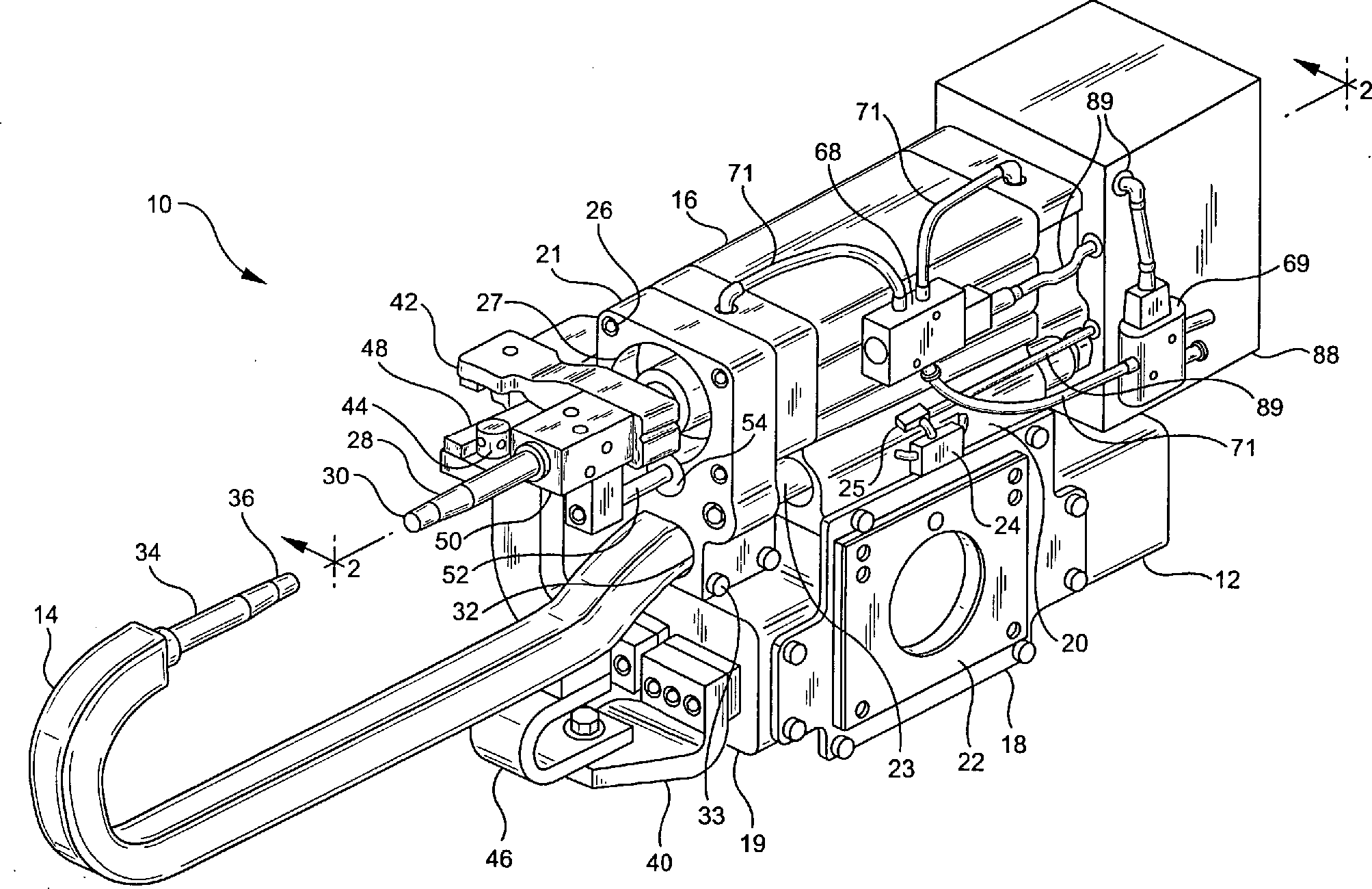
In 1 ist eine servo-pneumatische modulare Schweißzange 10 gezeigt, die gemäß der vorliegenden Erfindung gefertigt ist. Die Schweißzange 10 enthält im allgemeinen ein Schweißzangen-Basismodul 12, einen J-förmigen Kanonenarm 14, einen Pneumatikzylinder 16 und eine Unter-Steuerungsvorrichtung 88.In 1 is a servo-pneumatic modular welding gun 10 shown manufactured according to the present invention. The welding tongs 10 generally includes a welding tongs base module 12 , a J-shaped gun arm 14 , a pneumatic cylinder 16 and a sub-control device 88 ,

Das Schweißzangen-Basismodul 12 ist so aufgebaut, daß es als Plattform für eine Vielzahl von Bauarten verwendet werden kann. Mit anderen Worten bleibt das Basismodul 12 unabhängig von der Art des verwendeten Pneumatikzylinders oder des verwendeten Kanonenarms dasselbe. Durch Austauschen stationärer Kanonenarme kann eine große Vielzahl von Schweißbedingungen erfüllt werden, während die Gesamtzahl der Schweißzangen-Komponenten minimal gehalten wird. Eine Verringerung der Anzahl der Schweißzangen-Komponenten kommt dem Endkunden zugute, indem sowohl die Anforderungen an Ersatz-Schweißzangen und die Ersatzteil-Lagerhaltung verringert werden. Die Wartungskosten und die Ausbildung werden aufgrund der Gemeinsamkeit des Basismoduls ebenfalls minimiert.The welding tongs base module 12 is constructed so that it can be used as a platform for a variety of types. In other words, the base module remains 12 regardless of the type of pneumatic cylinder or gun arm used. By replacing stationary gun arms, a wide variety of welding conditions can be met while minimizing the total number of welding gun components. A reduction in the number of welding gun components benefits the end customer by reducing both the requirements for replacement welding guns and spare parts warehousing. Maintenance costs and training are also minimized due to the commonality of the base module.

Das Basismodul 12 umfaßt eine Basis 18, einen Schweißtransformator 19, eine Ausgleichsanordnung 20, einen Schweißzangen-Basisflansch 21 sowie Montageklammern 22. Die Basis 18, der Basisflansch 21 und die Montageklammern 22 werden aus hochfestem Aluminium mit Flugzeugqualität maschinell gefertigt, wodurch das Gesamtgewicht des Basismoduls 12 veringert wird, jedoch die notwendige Festigkeit erzeugt wird. Die Montageklammern 22 sind an zwei Seiten und am Boden der Basis 18 vorgesehen, um die Anbringung der Schweißzange 10 an einem Roboterarm oder einer. anderen Montagelinien-Schweißmaschine in irgendeiner von drei Konfigurationen zu ermöglichen. Alle Teile werden aus Strangmaterial bzw. Barrenmaterial gefertigt, wodurch das Gewicht verringert und die Notwendigkeit für Gießmuster beseitigt wird, wodurch die Herstellungszeit verringert wird.The basic module 12 includes a base 18 , a welding transformer 19 , a balancing arrangement 20 , a welding gun base flange 21 as well as mounting brackets 22 , The base 18 , the base flange 21 and the mounting brackets 22 are machined from high quality aircraft grade aluminum, reducing the overall weight of the base module 12 is reduced, but the necessary strength is generated. The mounting brackets 22 are on two sides and at the bottom of the base 18 provided to attach the welding gun 10 on a robotic arm or a. enable other assembly line welding machine in any of three configurations. All parts are made of billet material which reduces weight and eliminates the need for foundry patterns, thereby reducing manufacturing time.

Der Transformator 19, die Ausgleichsanordnung 20 und die Montageklammern 22 sind mit der Basis 18 durch Bolzen verbunden. Der Schweißtransformator 19 enthält elektrische Verbindungsstücke (nicht gezeigt) zur Verbindung mit einer externen Stromquelle und erzeugt den notwendigen Strom zu der Schweißzange. Die offene Gestaltung des Basismoduls 12 ermöglicht eine Vielzahl von Schweißtransformatoren, wie z. B. Wechselstrom- und Gleichstrom-US-Standards wie auch ISO-Standard-Bauarten.The transformer 19 , the balancing arrangement 20 and the mounting brackets 22 are with the base 18 connected by bolts. The welding transformer 19 includes electrical connectors (not shown) for connection to an external power source and generates the necessary current to the welding gun. The open design of the base module 12 allows a variety of welding transformers, such. B. AC and DC US standards as well as ISO standard types.

Die Ausgleichsanordnung 20 ist ein herkömmlicher Pneumatikzylinder mit einer Kolbenstange 12, die sich hiervon nach außen erstreckt. An dem Ende der Kolbenstange 23 ist der Schweißzangen-Basisflansch 21 befestigt. Somit bewegt sich der Basisflansch 21 zusammen mit der Kolbenstange 23 der Ausgleichsanordnung 20. Die Ausgleichsanordnung 20 enthält ein Proportional-Steuerungsventil 24 und einen Druckregler 25 zum Steuern und Überwachen des Luftdrucks, der durch Pneumatikzylinder zugeführt wird, zum Ausfahren und Einziehen der Ausgleichs-Kolbenstange 23. Der Betrieb der Ausgleichsanordnung 20 wird weiter unten ausführlich beschrieben.The balancing arrangement 20 is a conventional pneumatic cylinder with a piston rod 12 which extends to the outside thereof. At the end of the piston rod 23 is the welding gun base flange 21 attached. Thus, the base flange moves 21 together with the piston rod 23 the balancing arrangement 20 , The balancing arrangement 20 contains a proportional control valve 24 and a pressure regulator 25 for controlling and monitoring the air pressure supplied by pneumatic cylinders for extending and retracting the compensating piston rod 23 , The operation of the balancing arrangement 20 will be described in detail below.

Ebenfalls mit dem Basismodul 12 verbunden sind eine Transformator-Busstange 40, eine bewegliche Busstange 42, Elektrodenadapter 44, ein stationärer Nebenschluß 46 und ein beweglicher Nebenschluß 48 zum Erzeugen elektrischer Verbindungen zu dem Schweißtransformator 19. Die bewegliche Busstange 42 und der bewegliche Nebenschluß 48 sind mit einem beweglichen Schaftabschnitt 28 des Pneumatikzylinders 16 durch einen Arm 50 verbunden, der einen Führungsschaft 52 enthält, der in einem in dem Basisflansch 21 befestigten Lager 44 mit einem Drehzapfen gelagert ist. Der Führungsschaft 52 und das Lager 54 helfen, um eine richtige Ausrichtung des beweglichen Schaftabschnitts 28 des Zylinderkolbens während der Bewegung zu gewährleisten.Also with the basic module 12 connected are a transformer bus bar 40 , a movable bus bar 42 , Electrode adapter 44 , a stationary shunt 46 and a movable shunt 48 for generating electrical connections to the welding transformer 19 , The moving bus bar 42 and the movable shunt 48 are with a movable shaft section 28 of the pneumatic cylinder 16 through an arm 50 connected to a leadership team 52 contains, in one in the base flange 21 fortified warehouse 44 is mounted with a pivot. The leadership 52 and the camp 54 help to get a proper alignment of the movable shaft section 28 to ensure the cylinder piston during the movement.

An dem Basismodul 12 nicht gezeigt sind herkömmliche Wasserleitungsanschlüsse und dazu gehörende innere Wasserdurchtritte und Verteiler zum Kühlen der Komponenten der Schweißzange. Jede beliebige Kühlsystem-Auslegung kann mit der Schweißzange der vorliegenden Erfindung verwendet werden. Derartige Systeme sind im Stand der Technik weitgehend bekannt und müssen nicht ausführlich besprochen werden.At the base module 12 not shown are conventional water line connections and associated internal water passages and manifolds for cooling the components of the welding gun. Any cooling system design can be used with the welding gun of the present invention. Such systems are well known in the art and need not be discussed in detail.

Der Basisflansch 21 enthält außerdem einen Kanonenarm-Aufnahmehohlraum 32 für die Befestigungs des Kanonenarms 14. Der Kanonenarm 14 ist ebenfalls aus einem hochfesten Aluminium in Flugzeugqualität maschinell gefertigt, um das Gewicht zu verringern. Der Kanonenarm 14 ist im allgemeinen J-förmig, wobei ein Ende an dem Basisflansch 21 befestigt ist und ein stationärer Schaft 34 mit einer Schweißspitze 36 an einem entgegengesetzten Ende davon befestigt ist. Der Kanonenarm 14 ist an dem Basisflansch 21 durch Bolzen 33 derart befestigt, daß der stationäre Schaftabschnitt 34 des Kanonenarms mit dem beweglichen Schaftabschnitt 28 des Zylinderkolbens axial ausgerichtet ist und ein Spalt zwischen den gegenüberliegenden Schweißspitzen der Schäfte gebildet wird. Wenn die Ausgleichsanordnung 20 aktiviert wird, bewegt sich daher der stationäre Schaftabschnitt 34 des Kanonenarms 14 zusammen mit der Ausgleichs-Kolbenstange 23 zu dem beweglichen Schaftabschnitt des Zylinderkolbens hin oder von ihm weg. Durch Austauschen unterschiedlicher Kanonenarme kann der Spalt zwischen den Schweißspitzen eingestellt werden. Der Kanonenarm 14 und der Pneumatikzylinder 16 sind nun wiederum mit dem Basisflansch 21 lösbar verbunden, um eine vollständige Austauschbarkeit zu erzeugen.The base flange 21 Also includes a gun arm receiving cavity 32 for the attachment of the gun arm 14 , The gun arm 14 is also machined from a high-strength aircraft-grade aluminum to reduce weight. The gun arm 14 is generally J-shaped with one end on the base flange 21 is attached and a stationary shaft 34 with a welding tip 36 attached to an opposite end thereof. The gun arm 14 is on the base flange 21 by bolts 33 fixed so that the stationary shaft portion 34 the gun arm with the movable shaft portion 28 the cylinder piston is axially aligned and a gap between the opposite welding tips of the shafts is formed. If the balancing arrangement 20 is activated, therefore moves the stationary shaft portion 34 of the cannon arm 14 along with the compensation piston rod 23 to the moving Shaft portion of the cylinder piston towards or away from him. By exchanging different gun arms, the gap between the welding tips can be adjusted. The gun arm 14 and the pneumatic cylinder 16 are now again with the base flange 21 releasably connected to produce full interchangeability.

Der Pneumatikzylinder 16 ist mit dem Basisflansch 21 durch Bolzen 26 verbunden. Der Basisflansch 21 ist mit einer Bohrung 27 gebildet, durch die sich die Zylinder-Kolbenstange erstreckt. Mit der Zylinder-Kolbenstange ist ein beweglicher Schaftabschnitt 28 verbunden, der eine Schweißspitze 30 an seinem äußeren Ende hat.The pneumatic cylinder 16 is with the base flange 21 by bolts 26 connected. The base flange 21 is with a hole 27 formed, through which the cylinder piston rod extends. With the cylinder piston rod is a movable shaft portion 28 connected, which is a welding tip 30 at its outer end.

Ein wichtiger Nutzen der vorliegenden Erfindung besteht darin, daß die Verwendung eines Mehrfachpositions-Pneumatikzylinders vom Standard ISO 6431 ermöglicht wird. Ein geeigneter Pneumatikzylinder zur Verwendung mit der Schweißzange der vorliegenden Erfindung ist das Modell Nr. DNC 125–200 Markenbezeichnung das von der Festo-Corporation in Hauppauge, New York, gefertig wird. Wie oben besprochen, werden herkömmliche Schweißzangen gewöhnlicherweise unter Verwendung eines Drei-Positions-Zylinders speziell angefertigt. Wenn eine neue Anwendung erforderlich ist, muß die Schweißzange auseinandergebaut und für die neue Anwendung erneut konfiguriert werden. Es gibt somit praktisch keine Austauschbarkeit mit vorhandenen Schweißzangen. Durch Standardisieren des Pneumatikzylinders kann der Endnutzer verschiedene identische Schweißzangen bereithalten, die ohne weiteres ausgetauscht werden können. Hierdurch ergibt sich eine dramatische Verringerung der Stillstandszeit, wenn sich die Werkzeuganwendungen verändern. Wie weiter unten ausführlicher besprochen wird, wird die Standardisierung durch Einbauen eines internen Positionscodierers 78 in einem Standardzylinder und Bereitstellen einer Unter-Steuerungsvorrichtung 88 erzielt, um eine kontinuierliche Positionssteuerung mit geschlossener Schleife bzw. mit Rückkopplung zu erzeugen.An important benefit of the present invention is that it enables the use of a multi-position pneumatic cylinder of the ISO 6431 standard. A suitable pneumatic cylinder for use with the welding gun of the present invention is the Model No. DNC 125-200 brand name manufactured by Festo Corporation of Hauppauge, New York. As discussed above, conventional welding tongs are custom made using a three-position cylinder. If a new application is required, the welding gun must be disassembled and reconfigured for the new application. There is thus virtually no interchangeability with existing welding tongs. By standardizing the pneumatic cylinder, the end user can have various identical welding guns ready for replacement. This results in a dramatic reduction in downtime as tooling applications change. As will be discussed in more detail below, standardization is accomplished by incorporating an internal position encoder 78 in a standard cylinder and providing a sub-control device 88 achieved to produce a continuous closed-loop position feedback control.

Kontinuierliche Positionierungssteuerung mit geschlossener Schleife bzw. Rückkopplung bedeutet, daß die tatsächliche Position der Schweißspitze 30 durch den internen Positionscodierer 78 kontinuierlich überwacht wird, und diese Information wird zur Unter-Steuerungsvorrichtung 88 gesendet, wo sie mit Eingabeinformation verglichen wird, die einer gewünschten Schweißspitzen-Position enspricht. Die Position der Schweißspitze 30 wird dann auf der Grundlage des Vergleichs der tatsächlichen Positon und der Eingabeinformation durch die Unter-Steuerungsvorrichtung 88 automatisch eingestellt.Continuous closed-loop positioning control means that the actual position of the welding tip 30 through the internal position encoder 78 is continuously monitored, and this information becomes the sub-control device 88 where it is compared to input information corresponding to a desired weld position. The position of the welding tip 30 is then based on the comparison of the actual position and the input information by the sub-control device 88 automatically set.

2 veranschaulicht einen Querschnitt des Pneumatikzylinders 16 entlang der Linie 2-2 in 1. Der Pneumatikzylinder 16 enthält im allgemeinen ein zylindrisches Gehäuse 56, Lagerkappen 58 und 60, einen Kolben 62 und eine Kolbenstange 64. Die Lagerkappen 58 und 60 sind an den Enden des zylindrischen Gehäuses 56 befestigt, um dadurch eine Kolbenkammer 66 darin zu bilden. Die Lagerkappen 58 und 60 enthalten Anschlüsse 67 zur Verbindung mit einer Druckluftquelle durch ein Proportional-Steuerungsventil 68 und einen Proportional-Druckregler 69, die in 1 gezeigt sind. Der Proportional-Druckregler 69 überwacht und steuert Druckluft, die zu dem Proportional-Steuerungsventil 68 durch die Pneumatikleitungen 71 wandert, wie weiter unten ausführlich beschrieben wird. Die vordere Lagerkappe 58 enthält außerdem eine mittige Bohrung 70, durch die sich die Kolbenstange 64 bewegen kann. Der Kolben 62 ist an der Kolbenstange 64 befestigt und bildet eine luftdichte Abdichtung gegenüber dem Inneren des Zylindergehäuses 56, so daß beim Zuführen von Druckluft durch einen der Anschlüsse 67 einer der Lagerkappen sich der Kolben in einer von dem zugeführten Druck weggewandten Richtung bewegt, wodurch die Kolbenstange 64 in einer axialen Richtung bewegt wird. Die Standardbohrung für die innere Kammer 66 ist eine 125 mm-Bohrung, und der Hub der Kolbenstange 64 ist 185 mm. 2 illustrates a cross section of the pneumatic cylinder 16 along the line 2-2 in 1 , The pneumatic cylinder 16 generally includes a cylindrical housing 56 , Bearing caps 58 and 60 , a piston 62 and a piston rod 64 , The stock caps 58 and 60 are at the ends of the cylindrical housing 56 attached to thereby a piston chamber 66 to form in it. The stock caps 58 and 60 contain connections 67 for connection to a compressed air source through a proportional control valve 68 and a proportional pressure regulator 69 , in the 1 are shown. The proportional pressure regulator 69 monitors and controls compressed air coming to the proportional control valve 68 through the pneumatic lines 71 migrates, as described in detail below. The front bearing cap 58 also contains a central hole 70 through which the piston rod 64 can move. The piston 62 is on the piston rod 64 attached and forms an airtight seal against the interior of the cylinder housing 56 so that when supplying compressed air through one of the ports 67 one of the bearing caps, the piston moves in a direction away from the supplied pressure, whereby the piston rod 64 is moved in an axial direction. The standard hole for the inner chamber 66 is a 125 mm bore, and the stroke of the piston rod 64 is 185 mm.

Innerhalb der mittigen Bohrung 70 der vorderen Lagerkappe 58 ist ein metallischer Schaberring 72 befestigt, der zwischen einem Schnappring 73 und einem Lager 74 an seinem Ort gehalten wird. Der Schaberring 72 hat einen Innendurchmesser, der so bemessen ist, daß der Schaberring mit dem Umfangsrand der Kolbenstange 64 innig in Berührung ist. Wenn sich die Kolbenstange 64 bewegt, entfernt der Schaberring somit jegliche Schweißschlacke, die sich an der Kolbenstange anhäufen kann, wodurch verhindert wird, daß derartige zerriebene Ablagerungen in die innere Kammer 66 des Pneumatikzylinders 14 eindringen.Inside the central hole 70 the front bearing cap 58 is a metallic scraper ring 72 fastened between a snap ring 73 and a warehouse 74 is held in its place. The scraper ring 72 has an inner diameter which is dimensioned so that the scraper ring with the peripheral edge of the piston rod 64 is intimately in touch. When the piston rod 64 Thus, the scraper ring thus removes any weld slag which may accumulate on the piston rod, thereby preventing such grated deposits from entering the inner chamber 66 of the pneumatic cylinder 14 penetration.

Der Pneumatikzylinder 14 ist mit einer gehärteten und mit C45-Chrom beschichteten Kolbenstange 64 ausgestattet, die entlang ihrer Mittenlinie zur Bildung einer axialen Bohrung 76 darin angebohrt wurde. Die axiale Bohrung 76 ist bemessen, daß sie den inneren Positonscodierer 78 aufnimmt. Die Kolbenstange 64 enthält weiterhin einen Verriegelungsring 80, der an ihrem äußeren Ende befestigt ist, um die Anbringung des beweglichen Arms 50, des beweglichen Schaftabschnitts 28 und der Schweißspitze 30 daran zu erleichtern.The pneumatic cylinder 14 is equipped with a hardened and C45-chrome coated piston rod 64 fitted along its center line to form an axial bore 76 was drilled in it. The axial bore 76 is dimensioned to be the inner position encoder 78 receives. The piston rod 64 also contains a locking ring 80 which is attached at its outer end to the attachment of the movable arm 50 , the movable shaft portion 28 and the welding tip 30 to facilitate it.

Der innere Positionscodierer 78 ist vorzugsweise ein lineares Potentiometer, das an einem Ende mit der hinteren Lagerkappe 60 mit Edelstahl-Nylon-Verriegelungsmuttern 81 befestigt ist. Das lineare Potentiometer 78 enthält außerdem eine an dem äußeren Ende der Kolbenstange 64 befestigte Sonde 82. Ein geeignetes lineares Potentiometer für die Verwendung mit der Schweißzange der vorliegenden Erfindung trägt die Teile-Nummer 04LF8258 Markenbezeichnung und wird von der Betatronics Inc. in Hauppauge, New York hergestellt. 2 zeigt ein Verfahren zum Befestigen der Kolbensonde 82 an der Kolbenstange 64. Eine Schraube 83 mit einem inneren axialen Gewinde 84 ist in die Endfläche des äußeren Endes der Kolbenstange 64 eingeschraubt. Die Sonde 82 wird dann in das innere Gewinde der Schraube geschraubt, wodurch die Sonde an der Kolbenstange befestigt wird. Das Potentiometer 78 hat einen Arbeitshub von 10 Zoll (254 mm), wovon nur 7,28 Zoll (185 mm) verwendet werden. Wenn die Kolbenstange 64 vollständig eingezogen ist, hat das Potentiometer einen Totbereich von 1,35 Zoll (34 mm), was genauso ist, als ob sie vollständig ausgefahren wäre. Das lineare Potentiometer 78 arbeitet auf eine bekannte Art und Weise, wobei die Aus legung der Sonde 82 genau gemessen werden kann. Folglich können die Position und die Bewegung der Kolbenstange 64 genau überwacht werden.The inner position encoder 78 is preferably a linear potentiometer, which at one end with the rear bearing cap 60 with stainless steel nylon locking nuts 81 is attached. The linear potentiometer 78 Also includes one at the outer end of the piston rod 64 attached probe 82 , A suitable linear potentiometer for use with the welding gun of the present invention is part number 04LF8258, and manufactured by Betatronics Inc. of Hauppauge, New York. 2 shows a method for attaching the piston probe 82 on the piston rod 64 , A screw 83 with an internal axial thread 84 is in the end face of the outer end of the piston rod 64 screwed. The probe 82 is then screwed into the internal thread of the screw, whereby the probe is attached to the piston rod. The potentiometer 78 has a 10 inch (254 mm) working stroke, of which only 7.28 inches (185 mm) are used. When the piston rod 64 Fully retracted, the potentiometer has a dead band of 1.35 inches (34 mm), which is exactly as if it were fully extended. The linear potentiometer 78 works in a known manner, with the interpretation of the probe 82 can be measured exactly. Consequently, the position and movement of the piston rod can 64 be closely monitored.

Ein Elektro-Verschlußkasten 85 ist mit der hinteren Lagerkappe 60 verbunden, um die Potentiometerverdrahtung aufzunehmen. Der Elektro-Verschlußkasten 85 enthält außerdem elektrische Verbindungsglieder 86, um die elektrische Verbindung zwischen dem linearen Potentiometer 78 und einer Unter-Steuerungsvorrichtung 88 zu erleichtern. Die Unter-Steuerungsvorrichtung 88 ist die Schnittstelle zwischen der Schweißzange 10 und einer Haupt-Steuerungsvorrichtung (nicht gezeigt). Die Unter-Steuerungsvorrichtung 88 ist im wesentlichen ein Mikroprozessor, der Signale von der Codiervorrichtung 70, dem Proportional-Druckregler 69 und dem Ausgleichs-Druckregler 25 empfängt und diese Signale mit Signalen vergleicht, die von der Haupt-Steuerungsvorrichtung empfangen werden. Das Proportional-Steuerungsventil 68, der Proportional-Druckregler 69, das Ausgleichs-Steuerungsventil 24 und der Ausgleichs-Druckregler 25 sind allesamt durch Leitungen 89 mit der Unter-Steuerungsvorrichtung 88 elektrisch verbunden.An electric lock box 85 is with the rear bearing cap 60 connected to receive the potentiometer wiring. The electric lock box 85 also contains electrical connectors 86 to the electrical connection between the linear potentiometer 78 and a sub-control device 88 to facilitate. The sub-control device 88 is the interface between the welding gun 10 and a main control device (not shown). The sub-control device 88 is essentially a microprocessor that receives signals from the encoder 70 , the proportional pressure regulator 69 and the equalizing pressure regulator 25 receives and compares these signals with signals received from the main controller. The proportional control valve 68 , the proportional pressure regulator 69 , the balancing control valve 24 and the equalizing pressure regulator 25 are all through lines 89 with the sub-control device 88 electrically connected.

Die Schweißzange 10 arbeitet im allgemeinen auf die folgende Art und Weise. Wenn die Schweißspitzen 30 und 36 in einer vollständig offenen Stellung sind, positioniert ein Roboterarm die Schweißzange so, daß sich das Metall-Werkstück zwichen den Schweißspitzen befindet. Die Ausgleichsanordnung 20 wird aktiviert, um die Ausgleichs-Kolbenstange 23 einzuziehen und die Schweißspitze 36 zu dem Werkstück hin zu bewegen, bis es zu einem Kontakt kommt. So stützt man das Werkstück während des Schweißens ab und verhindert eine Beschädigung des Pneumatikzylinders 16. Sobald das Werkstück abgestützt ist, wird der Pneumatikzylinder 16 akti viert, um die Schweißspitze 30 zu dem Werkstück hin zu bewegen. Sobald die Schweißspitze 30 das Werkstück kontaktiert, erzeugt der Transformator 19 einen gewünschten Strom zwischen den Schweißspitzen 30 und 36. Der Strom tritt durch das Metall-Werkstück hindurch, wodurch das Metall geschmolzen wird und eine Verschweißung erzeugt wird. Wenn die Verschweißung abgeschlossen ist, zieht der Pneumatikzylinder 16 die Schweißspitze 30 zu einer Mittelpunkt-Position zurück, und das Werkstück und/oder die Kanone wird an einen neuen Ort bewegt, woraufhin sich der Zyklus wiederholt.The welding tongs 10 generally works the following way. When the welding tips 30 and 36 In a fully open position, a robotic arm positions the welding gun so that the metal workpiece is between the welding tips. The balancing arrangement 20 is activated to the balancing piston rod 23 to feed and the welding tip 36 to move towards the workpiece until it comes to a contact. To support the workpiece during welding and prevents damage to the pneumatic cylinder 16 , Once the workpiece is supported, the pneumatic cylinder 16 Acti fourth to the welding tip 30 to move towards the workpiece. Once the welding tip 30 contacted the workpiece, the transformer generates 19 a desired current between the welding tips 30 and 36 , The current passes through the metal workpiece, melting the metal and creating a weld. When the welding is complete, the pneumatic cylinder pulls 16 the welding tip 30 to a mid-point position, and the workpiece and / or gun is moved to a new location, whereupon the cycle repeats.

Wie oben erwähnt, wird durch Einziehen der Schweißspitze 30 zu einer Mittelpunkt-Position anstatt zu einer vollständig eingezogenen Position die Zykluszeit zwischen den Verschweißungen stark verringert. Durch den Einbau eines internen Positioniercodierers 78 und einer Unter-Steuerungsvorrichtung 88 ermöglicht die vorliegende Erfindung die Programmierung jeder beliebigen Mittelpunkt-Position durch die Haupt-Steuerungsvorrichtung. Zusätzlich werden andere Eigenschaften, wie z. B. eine Spitzenabnutzungs-Kompensation, eine Spitzendämpfung und eine genaue Kalibrierung erreicht, wie weiter unten ausführlich beschrieben wird.As mentioned above, by retracting the welding tip 30 to a midpoint position rather than a fully retracted position greatly reduces the cycle time between welds. By installing an internal positioning encoder 78 and a sub-control device 88 For example, the present invention allows the programming of any midpoint position by the main controller. In addition, other properties, such. For example, peak wear compensation, peak attenuation, and accurate calibration are achieved, as described in detail below.

Die Haupt-Steuerungsvorrichtung koordiniert die gesamte Bewegung, die Drucksteuerung sowie die Sequenzierung für den Schweißzangen-Roboterarm auf der Grundlage ihres eigenen internen Programms und der Rückkopplung von der Unter-Steuerungsvorrichtung 88. Dies wird erreicht durch die Übertragung von Bitsequenzen zwischen der Haupt-Steuerungsvorrichtung und der Unter-Steuerungsvorrichtung 88. Die Haupt-Steuerungsvorrichtung und die Unter-Steuerungsvorrichtung kommunizieren miteinander durch ein standardmäßiges Kommunikationsprotokoll, das als DeviceNet bezeichnet wird. Die folgende Tabelle ist eine Bitkarte, welche die Eingaben der Haupt-Steuerungsvorrichtung von der Unter-Steuerungsvorrichtung und die Ausgaben der Haupt-Steuerungsvorrichtung zu der Unter-Steuerungsvorrichtung zeigt.The main controller coordinates all movement, pressure control and sequencing for the welding gun robotic arm based on their own internal program and feedback from the sub-controller 88 , This is achieved by the transmission of bit sequences between the main controller and the sub-controller 88 , The main controller and the sub-controller communicate with each other through a standard communication protocol called DeviceNet. The following table is a bit map showing the inputs of the main control device from the sub-control device and the outputs of the main control device to the sub-control device.

Tabelle 1Table 1

Bit-KarteBit card

Eingabenentries

  • Nxx:i01 – System EIN/System OKNxx: i01 system ON / System OK
  • Nxx:i02 – Position erreichtNxx: i02 position reached
  • Nxx:i03 – Positioniert für Verschweißung (Stapelung OK)Nxx: i03 - Positioned for welding (stacking OK)
  • Nxx:i04 – Positions-Überbewegung (gezogene Kappe)Nxx: i04 - Position override (drawn cap)
  • Nxx:i05 – Ausgleichsdruck erzieltNxx: i05 - compensation pressure achieved
  • Nxx:i06 – Schweißdruck erzieltNxx: i06 - welding pressure achieved
  • Nxx:i07 – System kalibriertNxx: i07 system calibrated

Ausgabenexpenditure

  • Nxx:o01 – Kanonenspitzen-SchließtaktNxx: o01 - Cannon tip close cycle
  • Nxx:o02 – Kalibriere SchweißspitzeNxx: o02 - Calibrate welding tip
  • Nxx:o03 – Kanonen-Vorwärts-/Rückwärts-TaktNxx: o03 - Gun Forward / Reverse Clock
  • Nxx:o04 – Vorwärts-/Rückwärts-Position Bit 1Nxx: o04 - forward / reverse position Bit 1
  • Nxx:o05 – Vorwärts-/Rückwärts-Position Bit 2Nxx: o05 - forward / reverse position Bit 2
  • Nxx:o06 – Vorwärts-/Rückwärts-Position Bit 3Nxx: o06 - forward / reverse position Bit 3
  • Nxx:o07 – Vorwärts-/Rückwärts-Position Bit 4Nxx: o07 - forward / reverse position Bit 4
  • Nxx:o08 – Spitzenschließ- und Schweißposition Bit 1Nxx: o08 - tip closing and welding position Bit 1
  • Nxx:o09 – Spitzenschließ- und Schweißposition Bit 2Nxx: o09 - tip closing and welding position Bit 2
  • Nxx:o10 – Spitzenschließ- und Schweißposition Bit 3Nxx: o10 - tip closing and welding position Bit 3
  • Nxx:o11 – Spitzenschließ- und Schweißposition Bit 4Nxx: o11 - tip closing and welding position Bit 4
  • Nxx:o12 – Schweißdruck Bit 1Nxx: o12 - welding pressure bit 1
  • Nxx:o13 – Schweißdruck Bit 2Nxx: o13 - welding pressure bit 2
  • Nxx:o15 – Schweißdruck Bit 3Nxx: o15 - welding pressure bit 3
  • Nxx:o16 – Schweißdruck Bit 4Nxx: o16 - welding pressure bit 4
  • Nxx:o17 – Spitze bewegen (+)Nxx: o17 - top move (+)
  • Nxx:o18 – Spitze bewegen (–)Nxx: o18 - top move (-)
  • Nxx:o19 – Ausgleichsdruck Bit 1Nxx: o19 - equalizing pressure Bit 1
  • Nxx:o20 – Ausgleichsdruck Bit 2Nxx: o20 - compensation pressure Bit 2
  • Nxx:o21 – Ausgleichsdruck Bit 3Nxx: o21 - compensation pressure Bit 3
  • Nxx:o22 – Ausgleichsdruck Bit 4Nxx: o22 - compensation pressure Bit 4

Die Haupt-Steuerungsvorrichtung steuert die Schweißzange durch Manipulieren einer Sequenz von binären Bits. Die Bits 1 bis 4 werden manipuliert, um verschiedene Betriebsparameter in Abhängigkeit von der Ausgabeadresse der Haupt-Steuerungsvorrichtung zu erstellen. Das Bit 5 ist ein Takt-Bit, das den ausgeführten Befehl trägt bzw. mitführt.The Main control device controls the welding gun by manipulating a Sequence of binary Bits. Bits 1 through 4 are manipulated to different operating parameters dependent on from the output address of the main control device to create. Bit 5 is a clock bit which carries the executed instruction or carries.

Ein "Ein"-Bit von der Haupt-Steuerungsvorrichtung-Ausgabe Nxx:o12 schaltet das Schweißzangensystem ein. Die Haupt-Steuerungsvorrichtung-Ausgaben Nxx:o04–07 steuern die Mittelpunkt-Position der Pneumatikzylinder-Kolbenstange 64 auf der Grundlage einer Rückkopplung von dem internen Codierer 78. Die Kolbenstange 64 hat einen möglichen Hub von 150 mm für Positionierzwecke. Die Vorwärts-/Rückwärts-Positionsadressen Nxx:o04–07 stellen 0 mm–150 mm in 10 mm-Inkrementen gemäß der in Tabelle 2 gezeigten folgenden Bitsequenz dar. Tabelle 2 Vorschub-/Einzug-Positionstabelle Bit 1 Nxx:o04 Bit 2 Nxx:o05 Bit 3 Nxx:o06 Bit 4 Nxx:o07 Meßposition 0 0 0 0 0 mm geschlossen 0 0 0 1 10 mm 0 0 1 0 20 mm 0 0 1 1 30 mm 0 1 0 0 40 mm 0 1 0 1 50 mm 0 1 1 0 60 mm 0 1 1 1 70 mm 1 0 0 0 80 mm 1 0 0 1 90 mm 1 0 1 0 100 mm 1 0 1 1 110 mm 1 1 0 0 120 mm 1 1 0 1 130 mm 1 1 1 0 140 mm 1 1 1 1 150 mm An "on" bit from the main controller output Nxx: o12 turns on the welding gun system. The main controller outputs Nxx: o04-07 control the midpoint position of the pneumatic cylinder piston rod 64 based on feedback from the internal encoder 78 , The piston rod 64 has a possible stroke of 150 mm for positioning purposes. The forward / backward position addresses Nxx: o04-07 represent 0 mm-150 mm in 10 mm increments according to the following bit sequence shown in Table 2. Table 2 Feed / Pull-in Position Table Bit 1 Nxx: o04 Bit 2 Nxx: o05 Bit 3 Nxx: o06 Bit 4 Nxx: o07 measuring position 0 0 0 0 0 mm closed 0 0 0 1 10 mm 0 0 1 0 20 mm 0 0 1 1 30 mm 0 1 0 0 40 mm 0 1 0 1 50 mm 0 1 1 0 60 mm 0 1 1 1 70 mm 1 0 0 0 80 mm 1 0 0 1 90 mm 1 0 1 0 100 mm 1 0 1 1 110 mm 1 1 0 0 120 mm 1 1 0 1 130 mm 1 1 1 0 140 mm 1 1 1 1 150 mm

Die Ausgabe Nxx:o03 "Ein" positioniert die Kolbenstange 64 an einem Ort gemäß der Bestimmung durch die Bitsequenz von Nxx:o04–07 und relativ zu der letzten Operation in der Kalibrierungsausgabe Nxx:o02. Dies wiederum kann nicht erzielt werden ohne eine positive Rückkopplung mittels geschlossener Schleife von der internen Positionierungs-Codiervorrichtung 78, die Signale zu der Unter-Steuerungsvorrichtung 88 zurücksendet für einen Vergleich mit den Ausgaben von der Haupt-Steuerungsvorrichtung.The output Nxx: o03 "on" positions the piston rod 64 at a location as determined by the bit sequence of Nxx: o04-07 and relative to the last operation in the calibration output Nxx: o02. This, in turn, can not be achieved without a positive closed loop feedback from the internal positioning encoder 78 supplying the signals to the sub-control device 88 returns for comparison with the outputs from the main controller.

Die Haupt-Steuerungsvorrichtung-Ausgaben Nxx:o08–11 verwenden ebenfalls eine 4-Bitsequenz, um die Schweißzange bis auf einen gewünschten Spalt zwischen den Schweißspitzen 30 und 36 zu schließen. Diese Bitsequenz gestattet eine automatische Kalibrierung und eine Spitzen- Dämpfungseigenschaft. Durch Manipulieren der Bitsequenz können die Schweißspitzen vor dem Schweißen bei einer "Spitze-geschlossen"-Position zu einem äußerlichen Spalt positioniert werden mit der in Tabelle 3 gezeigten folgenden Bitsequenz. Tabelle 3 Spitzenschließ- und Schweißpositionstabelle Bit 1 Nxx:o08 Bit 2 Nxx:o09 Bit 3 Nxx:o10 Bit 4 Nxx:o11 Hubposition 0 0 0 0 0 mm 0 0 0 1 1 mm 0 0 1 0 2 mm 0 0 1 1 3 mm 0 1 0 0 4 mm 0 1 0 1 5 mm 0 1 1 0 6 mm 0 1 1 1 7 mm 1 0 0 0 8 mm 1 0 0 1 9 mm 1 0 1 0 10 mm 1 0 1 1 11 mm 1 1 0 0 12 mm 1 1 0 1 13 mm 1 1 1 0 14 mm 1 1 1 1 15 mm The main controller outputs Nxx: o08-11 also use a 4-bit sequence to move the welding gun to a desired gap between the welding tips 30 and 36 close. This bit sequence allows automatic calibration and a peak damping characteristic. By manipulating the bit sequence, the welding tips can be positioned at an "apex closed" position to an external gap prior to welding with the following bit sequence shown in Table 3. Table 3 Peak closing and welding position table Bit 1 Nxx: o08 Bit 2 Nxx: o09 Bit 3 Nxx: o10 Bit 4 Nxx: o11 stroke position 0 0 0 0 0 mm 0 0 0 1 1 mm 0 0 1 0 2 mm 0 0 1 1 3 mm 0 1 0 0 4 mm 0 1 0 1 5 mm 0 1 1 0 6 mm 0 1 1 1 7 mm 1 0 0 0 8 mm 1 0 0 1 9 mm 1 0 1 0 10 mm 1 0 1 1 11 mm 1 1 0 0 12 mm 1 1 0 1 13 mm 1 1 1 0 14 mm 1 1 1 1 15 mm

Die in Tabelle 3 aufgeführten Hubpositionen sind relativ zum Ort der "Spitze-geschlossen"-Position und müssen vor dem Betrieb kalibriert werden. Die Schweißspitze hat einen relativen Hub von 15 mm für Schweißzwecke, wobei die Spitzegeschlossen-Position-Bits Nxx:o08–11 10 mm–15 mm in 1 mm-Inkrementen darstellen. Die Ausgabe Nxx:o01 "Ein" positioniert die Schweißspitze an einem Ort, der durch die Bitsequenz Nxx:o08–11 und relativ zu der letzten Operation des Kalibrierungsbits Nxx:o02 bestimmt ist.The listed in Table 3 Stroke positions are relative to the location of the "tip-closed" position and must be calibrated prior to operation become. The welding tip has a relative stroke of 15mm for welding, with the tip-closed position bits Nxx: o08-11 10 mm-15 mm in 1 mm increments. The output Nxx: o01 "On" positions the welding tip at a location specified by the bit sequence Nxx: o08-11 and relative to the last one Operation of the calibration bit Nxx: o02 is determined.

Eine dritte 4-Bit-Sequenz, die den Ausgaben Nxx:o13–16 entspricht, wird verwendet, um den an den Spitzen 30 und 36 angelegten Schweißdruck zu manipulieren, und eine vierte 4-Bit-Sequenz, die den Ausgaben Nxx:o19–22 entspricht, wird verwendet, um den Ausgleichsdruck zu manipulieren. Der Schweißspitzen-Druck hat einen Bereich von 90 psi mit einer Bitauflösung von opsi, die durch Sequenzieren der Bits entsprechend den Ausgaben Nxx:o13–16 eingestellt wird. Der Ausgleichsanordnung-Druck hat ebenfalls einen Bereich von 90 psi und einer Auflösung von 6 psi pro Bit, die durch Sequenzieren der Bits von dem Haupt-Steuerungsvorrichtungs-Ausgaben Nxx:o19–22 eingestellt wird. Tabelle 4 zeigt die Bitsequenz zum Einstellen sowohl des Schweißspitzen-Drucks als auch des Ausgleichsdrucks. Tabelle 4 Schweiß- und Ausgleichsdruck-Werttabelle Bit 1 Nxx:o13 Nxx:o19 Bit 2 Nxx:o14 Nxx:o20 Bit 3 Nxx:o15 Nxx:o21 Bit 4 Nxx:o16 Nxx:o22 Druck Schweißung Ausgleichsvorrichtung 0 0 0 0 0 psi 0 0 0 1 6 psi 0 0 1 0 12 psi 0 0 1 1 18 psi 0 1 0 0 24 psi 0 1 0 1 30 psi 0 1 1 0 36 psi 0 1 1 1 42 psi 1 0 0 0 48 psi 1 0 0 1 54 psi 1 0 1 0 60 psi 1 0 1 1 66 psi 1 1 0 0 72 psi 1 1 0 1 78 psi 1 1 1 0 84 psi 1 1 1 1 90 psi A third 4-bit sequence, corresponding to the outputs Nxx: o13-16, is used at the tips 30 and 36 to manipulate applied welding pressure, and a fourth 4-bit sequence corresponding to the outputs Nxx: o19-22 is used to manipulate the balance pressure. The spike pressure has a range of 90 psi with a bit resolution of opsi set by sequencing the bits corresponding to the outputs Nxx: o13-16. Equalizer pressure also has a range of 90 psi and a resolution of 6 psi per bit which is set by sequencing the bits from the main controller output Nxx: o19-22. Table 4 shows the bit sequence for adjusting both the weld tip pressure and the balance pressure. Table 4 Welding and balancing pressure table of values Bit 1 Nxx: o13 Nxx: o19 Bit 2 Nxx: o14 Nxx: o20 Bit 3 Nxx: o15 Nxx: o21 Bit 4 Nxx: o16 Nxx: o22 Pressure welding compensating device 0 0 0 0 0 psi 0 0 0 1 6 psi 0 0 1 0 12 psi 0 0 1 1 18 psi 0 1 0 0 24 psi 0 1 0 1 30 psi 0 1 1 0 36 psi 0 1 1 1 42 psi 1 0 0 0 48 psi 1 0 0 1 54 psi 1 0 1 0 60 psi 1 0 1 1 66 psi 1 1 0 0 72 psi 1 1 0 1 78 psi 1 1 1 0 84 psi 1 1 1 1 90 psi

Die Haupt-Steuerungsvorrichtungs-Eingaben Nxx:i05 und Nxx:i06 "Ein" werden verwendet, um die Druckausgabe des Proportional-Druckreglers 69 anzuzeigen, oder der Ausgleichs-Druckregler 25 befindet sich innerhalb einer +/–2%-Genauigkeit des beabsichtigten Drucks, der durch die Bitsequenz Nxx:o13–16 oder Nxx:o19–22 bestimmt wird. Der Schweißdruck-Befehl wird nur dann tätig, wenn die Spitze geschlossen- und die Schweißposition ausgeführt wird. Die Haupt-Steuerungsvorrichtung hat eine vollständige Kontrolle für den Ausgleichsdruck und muß je nach der Kanonenausrichtung notwendige Druckwerte ändern.The main controller inputs Nxx: i05 and Nxx: i06 "on" are used to control the pressure output of the proportional pressure controller 69 or the equalizing pressure regulator 25 is within a +/- 2% accuracy of the intended pressure as determined by the bit sequence Nxx: o13-16 or Nxx: o19-22. The weld pressure command only operates when the tip is closed and the welding position is executed. The main controller has complete control of the balance pressure and must change necessary pressure values depending on the gun orientation.

Die Haupt-Steuerungsvorrichtung-Ausgaben Nxx:o17 und Nxx:o18 werden verwendet, um die Schweißzange manuell zu betätigen. Die Ausgabe Nxx:o17 läßt den Zylinder zu einer Spitze-geschlossen-Position wandern, und die Ausgabe Nxx:o18 läßt den Zylinder zu einer Spitze-offen-Position wandern. Diese Eigenschaften ermöglichen das manuelle Ausfahren und Einfahren von der Haupt-Steuerungsvorrichtung.The Main controller outputs Nxx: o17 and Nxx: o18 used the welding tongs to operate manually. The output Nxx: o17 leaves the cylinder wander to a peak-closed position, and the output Nxx: o18 leaves the cylinder hike to a top-open position. These properties allow the manual extension and retraction of the main control device.

Die Haupt-Steuerungsvorrichtungs-Eingaben Nxx:i01–07 empfangen Signale von Unter-Steuerungsvorrichtung 88, die verschiedene Betriebsparameter der Schweißzangen anzeigen. Die Eingabe Nxx:i01 "Ein" zeigt der Haupt-Steuerungsvorrichtung an, daß das System eingeschaltet ist und kein fehlerhafter Zustand vorliegt. Die Eingabe Nxx:i02 "Ein" zeigt an, daß eine Vorschub/Einzug-Position erreicht worden ist. Die Eingabe Nxx:iO3 "Ein" zeigt an, daß der Schweißstapel innerhalb der zusätzlichen Toleranz liegt, während "Aus" anzeigt, daß der Stapel zu dick ist oder irgendetwas innerhalb des Weges der Schweißspitze stört. Die Eingabe Nxx:iO4 "Ein" zeigt der Haupt-Steuerungsvorrichtung die Positon über dem Weg oder einen Zustand der "gezogenen Kappe" an.The main controller inputs Nxx: i01-07 receive signals from sub-controller 88 indicating various operating parameters of the welding guns. The input Nxx: i01 "on" indicates to the main controller that the system is turned on and there is no erroneous state. The input Nxx: i02 "on" indicates that a feed / retract position has been reached. The input Nxx: iO3 "on" indicates that the welding stack is within the additional tolerance, while "off" indicates that the stack is too thick or interfering with anything within the path of the welding tip. The input Nxx: iO4 "on" indicates to the main controller the position over the path or a state of the "pulled cap".

Die Eingabe Nxx:i05 "Ein" zeigt an, daß der angewiesene Schweißdruck erreicht ist, der durch die Ausgaben Nxx:o13–16 ausgewählt wird. Die Eingabe Nxx:o06 "Ein" zeigt an, daß der angewiesene Ausgleichsdruck erzielt worden ist, der durch die Ausgaben Nxx:o19. 22 ausgewählt wurde. Schließlich zeigt die Eingabe Nxx:i07 "Ein" an, daß sich das System im Kalibrierungsmodus befindet, während "Aus" anzeigt, daß die Kalibrierung abgeschlossen ist und der Normalbetrieb erneut beginnen kann.The Input Nxx: i05 "On" indicates that the instructed welding pressure is reached, which is selected by the outputs Nxx: o13-16. The entry Nxx: o06 "On" indicates that the instructed Balancing pressure has been achieved by the expenditure Nxx: o19. 22 selected has been. After all displays the entry Nxx: i07 "On" indicating that the System is in calibration mode while "off" indicates that the Calibration is complete and normal operation starts again can.

Nachdem die Initialisierung und Kalibrierung abgeschlossen ist, läßt sich der Betrieb des Schweißzangensystems gemäß der vorliegenden Erfindung durch die folgenden Schritte darstellen:

  • 1. Einstellen der Bits Nxx:o04–Nxx:o07 für eine beabsichtigte Position.
  • 2. Halten des Bits Nxx:o03 auf einem hohen Wert, um zu der Position auszufahren.
  • 3. Einstellen der Bits Nxx:o13–Nxx:o16 für den gewünschten Druck.
  • 4. Einstellen der Bits Nxx:o08–Nxx:o11 für die gewünschte Metalldicke.
  • 5. Halten des Bits Nxx:o01 auf einem hohen Wert, um das Schweißen durchzuführen.
  • 6. Prüfen des Bits Nxx:iO3 für "Positioniert zum Schweißen".
  • 7. Prüfen des Bits Nxx:i06 für erreichten Schweißdruck.
  • 8. Prüfen des Bits Nxx:iO4, ob es bei abgezogener Kappe nicht an ist.
  • 9. Durchführen der Schweißung mit gesteuerter Schweißung.
  • 10. Fallenlassen des Bits Nxx:o01, um zu dem Ort zurückzukehren, der durch die Bits Nxx:o04–Nxx:o07 sequenziert wird und durch Nxx:o03 eingestellt ist.
  • 11. Fallenlassen des Bits Nxx:o03.
  • 12. Einstellen der neuen Rückfahrort-Schritte 1 bis 2.
  • 13. Einstellen des neuen Schweißdruck-Schrittes 3.
  • 14. Aussendendes neue-Dicke-Schrittes 4.
  • 15. Ausführen der Schweißsequenz-Schritte 5 bis 9.
  • 16. Ausführen des Einzieh-Schrittes 10 bis 11.
After the initialization and calibration is complete, the operation of the welding gun system according to the present invention can be represented by the following steps:
  • 1. Setting bits Nxx: o04-Nxx: o07 for an intended position.
  • 2. Hold the Nxx: o03 bit high to exit to the position.
  • 3. Setting the bits Nxx: o13-Nxx: o16 for the desired pressure.
  • 4. Set bits Nxx: o08-Nxx: o11 for the desired metal thickness.
  • 5. Hold the Nxx: o01 bit high to perform the welding.
  • 6. Check bit Nxx: iO3 for "Positioned for welding".
  • 7. Check bit Nxx: i06 for achieved welding pressure.
  • 8. Check the Nxx: iO4 bit if it is not on when the cap is removed.
  • 9. Perform welding with controlled welding.
  • 10. Drop bit Nxx: o01 to return to the location which is sequenced by bits Nxx: o04-Nxx: o07 and set by Nxx: o03.
  • 11. Dropping the Nxx bit: o03.
  • 12. Setting the new reversing steps 1 to 2.
  • 13. Set the new welding pressure step 3.
  • 14. Sending New Thickness Step 4.
  • 15. Perform welding sequence steps 5 through 9.
  • 16. Perform the pull-in step 10 to 11.

Für den Fachmann ist es selbstverständlich, daß die oben vorgestellten Tabellen lediglich der Veranschaulichung dienen. Natürlich kann je nach den Auslegungsparametern das Steuerungsprogramm modifiziert werden, um einem gewünschten Bedarf gerecht zu werden.For the expert it goes without saying that the Tables presented above are for illustrative purposes only. Naturally Depending on the design parameters, the control program can be modified, to a desired one Need to be met.

Der Pneumatikzylinder 14 ist daher mit einer Positions-Steuerungsvorrichtung ausgestattet, die ein Proportional- Steuerungsventil ansteuert, das mit einem oder beiden der Anschlüsse 68 der Lagerkappen 58 und 60 verbunden ist, um eine rückgekoppelte Positionierungssteuerung bzw. eine Positionierungsteuerung mit geschlossener Schleife für die Kolbenstange 64 zu erzeugen. Dieses System ist ausgestattet mit einer frei programmierbaren rückgekoppelten Positions- und Drucksteuerung aufgrund des internen Positionierungscodierers 78 und der Unter-Steuerungsvorrichtung 88. Außerdem lernt das Positionierungssystem und kompensiert jegliche Zylinderabnutzung über die Zeit hinweg und ermöglicht eine Spitzendämpfungs-Eigenschaft.The pneumatic cylinder 14 is therefore equipped with a position control device that drives a proportional control valve that is connected to one or both of the ports 68 the stock caps 58 and 60 connected to a closed loop positioning control or a closed loop positioning control for the piston rod 64 to create. This system is equipped with a freely programmable feedback position and pressure control due to the internal positioning encoder 78 and the sub-control device 88 , In addition, the positioning system learns and compensates for any cylinder wear over time and provides a peak dampening property.

Claims (15)

Servo-pneumatische Punktschweißzange (10), welche aufweist: ein Schweißzangen-Basismodul (12); einen Pneumatikzylinder (16), der an das Basismodul (12) angekoppelt ist und einen beweglichen Kolben enthält mit einer ersten Schweißelektrode (30), die mit seinem äußeren Ende verbunden ist für eine Hin- und Herbewegung von einem ersten Ende des Zylinders (16); einen Arm (14) mit einem ersten Ende, das an dem Schweißzangen-Basismodul (12) befestigt ist, und einem zweiten Ende, mit dem eine zweite Schweißelektrode (36) verbunden ist, wobei die zweite Schweißelektrode (36) axial ausgerichtet ist und zu der ersten Schweißelektrode (30) weist, wobei zwischen ihnen ein Spalt bestimmt wird; und eine eingebaute programmierbare Steuerungsvorrichtung (88) mit einem Mikroprozessor, die eine frei programmierbare Positions- und Schweißdrucksteuerung für den zwischen der ersten und der zweiten Schweißelektrode (30, 36) angelegten Schweißdruck aufweist, und die mit dem Pneumatikzylinder (16) funktionell verbunden ist, zum Steuern der Bewegung der ersten Schweißelektrode (30) zu einer Vielzahl programmierbarer diskreter Inkremente für einen Abschnitt der Hublänge des Pneumatikzylinders (16).Servo-pneumatic spot welding gun ( 10 ), comprising: a welding tongs base module ( 12 ); a pneumatic cylinder ( 16 ) connected to the base module ( 12 ) is coupled and includes a movable piston with a first welding electrode ( 30 ) connected to its outer end for reciprocating movement from a first end of the cylinder ( 16 ); an arm ( 14 ) having a first end attached to the welding tongs base module ( 12 ) and a second end to which a second welding electrode ( 36 ), the second welding electrode ( 36 ) is axially aligned and to the first welding electrode ( 30 ), whereby a gap is determined between them; and a built-in programmable control device ( 88 ) with a microprocessor having a freely programmable position and welding pressure control for between the first and second welding electrodes ( 30 . 36 ) and the pressure associated with the pneumatic cylinder ( 16 ) is operatively connected to control the movement of the first welding electrode ( 30 ) to a plurality of programmable discrete increments for a portion of the stroke length of the pneumatic cylinder ( 16 ). Servo-pneumatische Punktschweißzange nach Anspruch 1, dadurch gekennzeichnet, daß sie außerdem ein Proportionalfluß-Steuerungsventil (68) aufweist, das mit dem Pneumatikzylinder (16) für die Bewegung des Kolbens verbunden ist, wobei das Proportionalfluß-Steuerungsventil durch die programmierbare Steuerungsvorrichtung aktiviert wird.Servo-pneumatic spot welding gun according to claim 1, characterized in that it further comprises a proportional flow control valve ( 68 ), which with the pneumatic cylinder ( 16 ) for the movement of the piston, the proportional flow control valve being activated by the programmable controller. Servo-pneumatische Punktschweißzange nach Anspruch 1, dadurch gekennzeichnet, daß der Pneumatikzylinder (16) eine interne Positionierungs-Codiervorrichtung (78) enthält zum Erfassen der Kolbenposition und Übertragen von Kolben-Positionsinformation in der programmierbaren Steuerungsvorrichtung, um die Bewegung des Kolbens zu steuern.Servo-pneumatic spot welding gun according to claim 1, characterized in that the pneumatic cylinder ( 16 ) an internal positioning coding device ( 78 ) for detecting the piston position and transmitting piston position information in the programmable controller to control the movement of the piston. Servo-pneumatische Punktschweißzange nach Anspruch 3, dadurch gekennzeichnet, daß die interne Positionierungs-Codiervorrichtung (78) ein lineares Potentiometer ist oder aufweist.Servo-pneumatic spot welding gun according to claim 3, characterized in that the internal positioning coding device ( 78 ) is or has a linear potentiometer. Servo-pneumatische Punktschweißzange nach Anspruch 1, dadurch gekennzeichnet, daß das Schweißzangen-Basismodul (12) für eine lösbare Befestigung des Pneumatikzylinders (16) und des Arms (14) ausgelegt ist, wobei der Pneumatikzylinder (16) und der Arm (14) durch andere Pneumatikzylinder und Arme ausgetauscht werden können.Servo-pneumatic spot welding gun according to claim 1, characterized in that the welding tongs base module ( 12 ) for a releasable attachment of the pneumatic cylinder ( 16 ) and the arm ( 14 ), wherein the pneumatic cylinder ( 16 ) and the arm ( 14 ) can be replaced by other pneumatic cylinders and arms. Servo-pneumatische Punktschweißzange nach Anspruch 1, dadurch gekennzeichnet, daß das Schweißzangen-Basismodul (12) aus hochfestem maschinell bearbeiteten Aluminium besteht.Servo-pneumatic spot welding gun according to claim 1, characterized in that the welding tongs base module ( 12 ) consists of high-strength machined aluminum. Servo-pneumatische Punktschweißzange nach Anspruch 2, dadurch gekennzeichnet, daß das Proportionalfluß-Steuerungsventil (68) einstellbar ist, um Drücke im Bereich von 1112 N bis 7162 N zwischen den Schweißelektroden (30, 36) zu erzeugen.Servo-pneumatic spot welding gun according to claim 2, characterized in that the proportional flow control valve ( 68 ) is adjustable to pressures in the range of 1112 N to 7162 N between the welding electrodes ( 30 . 36 ) to create. Servo-pneumatische Punktschweißzange nach Anspruch 1, dadurch gekennzeichnet, daß der Pneumatikzylinder (16) eine Hublänge von etwa 185 mm und eine innere Bohrung von etwa 125 mm hat.Servo-pneumatic spot welding gun according to claim 1, characterized in that the pneumatic cylinder ( 16 ) has a stroke length of about 185 mm and an inner bore of about 125 mm. Servo-pneumatische Punktschweißzange nach Anspruch 1, dadurch gekennzeichnet, daß der Pneumatikzylinder (16) außerdem einen Schaberring (72) aufweist, der in dem ersten Ende des Zylinders befestigt ist, wobei der Schaberring (72) den Zylinderkolben entlang des Umfangs berührt, um von dem Kolben Abriebprodukte zu entfernen, wenn sich der Kolben hin- und herbewegt.Servo-pneumatic spot welding gun according to claim 1, characterized in that the pneumatic cylinder ( 16 ) also a scraper ring ( 72 ), which is fixed in the first end of the cylinder, wherein the scraper ring ( 72 ) contacts the cylinder piston along the circumference to remove abrasive products from the piston as the piston reciprocates. Servo-pneumatische Punktschweißzange nach Anspruch 3 oder 4, dadurch gekennzeichnet, daß die Positionierungs-Codiervorrichtung (78) Mittel zum Erfassen der Schweißspitzen-Position und Aussenden eines Schweißspitzen-Positionssignals an die Steuerungsvorrichtung aufweist, und dass die Steuerungsvorrichtung (88) Mittel zum Vergleichen der eingegebenen Positionsinformation mit dem Positionssignal und zum Aktivieren eines Steuerungsventils über ein Ausgabe-Steuerungssignal zur Betätigung eines Pneumatikzylinders aufweist, um die Schweißspitze auf der Grundlage des durch die Steuerungvorrichtung durchgeführten Vergleichs auszufahren oder einzuziehen.Servo-pneumatic spot welding gun according to claim 3 or 4, characterized in that the positioning coding device ( 78 ) Means for detecting the welding tip position and emitting a welding tip position signal to the control device, and that the control device ( 88 ) Means for comparing the input position information with the position signal and for activating a control valve via an output control signal for operating a pneumatic cylinder to extend or retract the welding tip based on the comparison made by the control device. Servo-pneumatische Punktschweißzange nach Anspruch 10, dadurch gekennzeichnet, daß die Eingabe-Positionsinformation eine Sequenz einer Vielzahl von Binärbit-Positionssequenzen aufweist, so daß jede Positionssequenz einer unterschiedlichen diskreten Schweißspitzen-Position entspricht.Servo-pneumatic spot welding gun according to claim 10, characterized characterized in that Input position information has a sequence of a plurality of binary bit position sequences, so that every position sequence corresponds to a different discrete welding tip position. Servo-pneumatische Punktschweißzange nach Anspruch 11, dadurch gekennzeichnet, daß die Bit-Positionssequenz vier binäre Bits aufweist, die 16 mögliche Schweißspitzen-Orte darstellen.Servo-pneumatic spot welding gun according to claim 11, characterized characterized in that Bit position sequence four binary Has 16 possible bits Welding tips places represent. Servo-pneumatische Punktschweißzange nach Anspruch 11, dadurch gekennzeichnet, daß ein Druckregler zum Erfassen des Schweißspitzen-Drucks und Aussenden eines Schweißspitzen-Drucksignals an die Steuerungsvorrichtung vorgesehen ist, dass ein die eingegebene Binärbit-Drucksequenz mit dem Schweißspitzen-Drucksignal vergleichender Vergleicher in der Steuerungsvorrichtung enthalten ist und dass das Steuerungsventil über ein Ausgabe-Steuerungssignal der Steuerungsvorrichtung (88) aktivierende Aktivierungsmittel zur Betätigung des Pneumatikzylinders (16) und zur Erhöhung oder Verringerung eines an die Schweißspitze angelegten Drucks auf der Grundlage des in der Steuerungsvorrichtung (88) durchgeführten Vergleichs zwischen dem Drucksignal und der Drucksequenz aufweist.A servo-pneumatic spot welding gun as claimed in claim 11, characterized in that a pressure regulator is provided for detecting the welding tip pressure and sending a welding tip pressure signal to the control device that includes a comparator in the control device which compares the input binary bit printing sequence with the welding tip pressure signal and that the control valve via an output control signal of the control device ( 88 ) activating activating means for actuating the pneumatic cylinder ( 16 ) and for increasing or decreasing a pressure applied to the welding tip on the basis of the in the control device ( 88 ) carried out comparison between the pressure signal and the print sequence. Servo-pneumatische Punktschweißzange nach Anspruch 11, gekennzeichnet durch Eingabemittel zum Eingeben einer Sequenz einer Vielzahl von Binärbit-Dämpfungssequenzen in die Steuerungsvorrichtung (88), wobei jede Dämpfungssequenz einer unterschiedlichen Schweißspitzen-Dämpfungsposition bezüglich einer voll ausgefahrenen Spitzenposition entspricht, Erfassungsmittel zum Erfassen der Schweißspitzen-Position bezüglich der voll ausgefahrenen Spitzenposition mit der Positionierungs-Codiervorrichtung (78) und Aussenden eines Schweißspitzen-Dämpfungssignals an die Steuerungsvorrichtung, Vergleichsmittel zum Vergleichen der eingegebenen Binärbit-Dämpfungssequenz mit dem Dämpfungssignal in der Steuerungsvorrichtung (88), Aktivierungsmittel zum Aktivieren des Steuerungsventils (68) über ein Ausgabesignal der Steuerungsvorrichtung (88), um durch Betätigung eines Pneumatikzylinders (16) die Schweißspitze zuerst in eine Dämpfungsposition auszufahren auf der Grundlage des in der Steuerungsvorrichtung durchgeführten Vergleichs zwischen dem Dämpfungssignal und der Dämpfungssequenz, und dann die Schweißspitze von der Dämpfungsposition zu der voll ausgefahrenen Position weiter auszufahrenA servo-pneumatic spot welding gun according to claim 11, characterized by inputting means for inputting a sequence of a plurality of binary-bit attenuation sequences to said control device (Fig. 88 ), wherein each damping sequence corresponds to a different welding tip damping position with respect to a fully extended tip position, detecting means for detecting the welding tip position with respect to the fully extended tip position with the positioning coding device (FIG. 78 ) and transmitting a welding spike attenuation signal to the control device, comparing means for comparing the input binary bit attenuation sequence with the attenuation signal in the control device (FIG. 88 ), Activating means for activating the control valve ( 68 ) via an output signal of the control device ( 88 ) by pressing a pneumatic cylinder ( 16 ) to extend the welding tip to a damping position first on the basis of the comparison made in the control device between the damping signal and the damping sequence, and then to further extend the welding tip from the damping position to the fully extended position Servo-pneumatische Punktschweißzange (10) nach einem der vorhergehenden Ansprüche, dadurch gekennzeichnet, daß der Pneumatikzylinder (16) einen Proportional-Druckregler enthält, der mit der Steuerungsvorrichtung (88) elektrisch verbunden ist, zum Regeln bzw. Einstellen des Betrags des pneumatischen Drucks in dem Pneumatikzylinder (16).Servo-pneumatic spot welding gun ( 10 ) according to any one of the preceding claims, characterized characterized in that the pneumatic cylinder ( 16 ) includes a proportional pressure regulator connected to the control device ( 88 ) is electrically connected to regulate the amount of pneumatic pressure in the pneumatic cylinder ( 16 ).
DE10162656A 2001-01-04 2001-12-20 Servo-pneumatic modular welding gun Revoked DE10162656B4 (en)

Applications Claiming Priority (2)

Application Number Priority Date Filing Date Title
US754481 1996-11-22
US09/754,481 US6455800B1 (en) 2001-01-04 2001-01-04 Servo-pneumatic modular weld gun

Publications (2)

Publication Number Publication Date
DE10162656A1 DE10162656A1 (en) 2002-07-25
DE10162656B4 true DE10162656B4 (en) 2008-06-26

Family

ID=25034980

Family Applications (1)

Application Number Title Priority Date Filing Date
DE10162656A Revoked DE10162656B4 (en) 2001-01-04 2001-12-20 Servo-pneumatic modular welding gun

Country Status (4)

Country Link
US (1) US6455800B1 (en)
JP (1) JP2002224846A (en)
BR (1) BR0200013A (en)
DE (1) DE10162656B4 (en)

Cited By (2)

* Cited by examiner, † Cited by third party
Publication number Priority date Publication date Assignee Title
DE102015013987B4 (en) 2014-11-06 2019-05-23 Fanuc Corporation Spot welding system and method with the ability to make a pressing force exerted on an object to be pressed constant
DE102010052717B4 (en) 2009-11-26 2021-11-11 Fanuc Corporation Method for controlling a spot welding system

Families Citing this family (17)

* Cited by examiner, † Cited by third party
Publication number Priority date Publication date Assignee Title
DE10356978A1 (en) 2003-12-05 2005-07-14 Bosch Rexroth Ag Module of a resistance welding gun
US7956308B2 (en) * 2005-05-18 2011-06-07 Parker-Hannifin Corporation Weld gun control system
FR2901164B1 (en) * 2006-05-16 2008-08-15 Aro Soc Par Actions Simplifiee CLAMP FOR SHEARING, USED IN ASSOCIATION WITH A MANIPULATING ARM, AND A DEPORTE BALANCING MODULE
FR2903034B1 (en) * 2006-07-03 2009-04-10 Aro Soc Par Actions Simplifiee PLIERS HAMMER, USED IN ASSOCIATION WITH A MANIPULATING ARM, AND ELECTROMECHANICAL BALANCING MODULE
JP5004048B2 (en) * 2007-07-03 2012-08-22 Smc株式会社 Cylinder device
US8304681B2 (en) * 2007-09-13 2012-11-06 Comau, Inc. Universal weld gun configuration
US20090192644A1 (en) * 2008-01-30 2009-07-30 Meyer Thomas J Method and system for manufacturing an article using portable hand-held tools
PL3138653T3 (en) * 2011-11-09 2018-05-30 Amada Miyachi Europe Gmbh Modular electrical processing facility, in particular for welding or soldering/brazing
US9144860B2 (en) * 2012-03-29 2015-09-29 Fanuc Robotics America Corporation Robotic weld gun orientation normalization
EP2664422B1 (en) * 2012-05-15 2015-07-22 COMAU S.p.A. Multi-axis industrial robot with integrated tool
JP6069647B2 (en) * 2012-11-02 2017-02-01 新光機器株式会社 Lower electrode for resistance welder
KR200478800Y1 (en) * 2015-04-16 2015-11-19 한국 오바라 주식회사 Drive unit of welding gun
DE102015120222A1 (en) * 2015-11-23 2017-05-24 Bürkert Werke GmbH Welding caps cooling water control
CN105382396B (en) * 2015-12-08 2018-03-16 天津七所高科技有限公司 A kind of integrated soldering turret with balance cylinder
PL3366409T3 (en) 2017-02-23 2019-12-31 Comau S.P.A. Articulated robot carrying an electric resistance welding head with electrodes located on the same side ; corresponding method of resistance electric welding on a component to be welded
DE102017112448A1 (en) * 2017-06-06 2018-12-06 Arnold & Shinjo Gmbh & Co. Kg Apparatus and method for producing a composite component and motor vehicle
JP6572281B2 (en) * 2017-10-06 2019-09-04 ファナック株式会社 Spot welding system

Citations (4)

* Cited by examiner, † Cited by third party
Publication number Priority date Publication date Assignee Title
DE3206432C2 (en) * 1982-02-23 1984-04-05 Festo-Maschinenfabrik Gottlieb Stoll, 7300 Esslingen Protective jacket for preventing weld spatter from adhering to a piston rod of a working cylinder on welding devices and a method for producing such a protective jacket
EP0569831A2 (en) * 1992-05-12 1993-11-18 Kabushiki Kaisha Sg Spot welding machine
US5478982A (en) * 1992-09-22 1995-12-26 Odawara Automation, Inc. Apparatus for fusing terminal or commutator wire connections on an armature or stator
EP1010491A2 (en) * 1998-12-16 2000-06-21 Dengensha Manufacturing Company Limited Welding machine and method for assembling same

Family Cites Families (18)

* Cited by examiner, † Cited by third party
Publication number Priority date Publication date Assignee Title
US2041913A (en) 1935-05-15 1936-05-26 Peter W Fassler Protable welding machine
US4447697A (en) * 1978-03-28 1984-05-08 Unimation, Inc. Weld gun repositioning system for programmable manipulator
US4403281A (en) * 1981-04-03 1983-09-06 Cincinnati Milacron Industries, Inc. Apparatus for dynamically controlling the tool centerpoint of a robot arm off a predetermined path
DE3520199A1 (en) 1984-10-05 1986-04-10 Wabco Westinghouse Steuerungstechnik GmbH & Co, 3000 Hannover POTENTIOMETER
US4724294A (en) * 1985-10-15 1988-02-09 D-M Automation Programmable welder
JPH0679787B2 (en) * 1988-01-26 1994-10-12 本田技研工業株式会社 Electrode tip management method for welding gun in automatic welding machine
US5412172A (en) * 1990-10-08 1995-05-02 Kabushiki Kaisha Sg Spot welding machine
US5150049A (en) 1991-06-24 1992-09-22 Schuetz Tool & Die, Inc. Magnetostrictive linear displacement transducer with temperature compensation
US5239155A (en) 1992-11-19 1993-08-24 Goran Olsson Multipurpose spot welding gun with replaceable electrode holders
US5477771A (en) 1993-08-10 1995-12-26 Black; Philip B. Hydraulic cylinder assembly
DE69406614T2 (en) * 1993-08-25 1998-06-25 Toyota Motor Co Ltd Control method for spot welding, and device that uses a controlled welding gun
EP0644014A1 (en) * 1993-09-17 1995-03-22 Toyota Jidosha Kabushiki Kaisha Welding apparatus and an operation method thereof
US5393950A (en) * 1994-04-08 1995-02-28 Eaton Corporation Electrode displacement monitoring and control
JPH1058157A (en) * 1996-06-13 1998-03-03 Kawasaki Heavy Ind Ltd Method and apparatus for controlling spot welding
JP3588668B2 (en) * 1997-08-27 2004-11-17 日産自動車株式会社 Estimation method of nugget diameter in spot welding
DE19738647A1 (en) * 1997-09-04 1999-03-25 Messer Griesheim Schweistechni Resistance pressure welding machine
US6225590B1 (en) * 1998-05-26 2001-05-01 Medar, Inc. Method for determining a condition of a resistance spotwelding system or a workpiece in the system
JP3761344B2 (en) * 1998-12-01 2006-03-29 トヨタ自動車株式会社 Welding gun and sensor calibration method using it, welding control method, welding spot position accuracy change management method

Patent Citations (4)

* Cited by examiner, † Cited by third party
Publication number Priority date Publication date Assignee Title
DE3206432C2 (en) * 1982-02-23 1984-04-05 Festo-Maschinenfabrik Gottlieb Stoll, 7300 Esslingen Protective jacket for preventing weld spatter from adhering to a piston rod of a working cylinder on welding devices and a method for producing such a protective jacket
EP0569831A2 (en) * 1992-05-12 1993-11-18 Kabushiki Kaisha Sg Spot welding machine
US5478982A (en) * 1992-09-22 1995-12-26 Odawara Automation, Inc. Apparatus for fusing terminal or commutator wire connections on an armature or stator
EP1010491A2 (en) * 1998-12-16 2000-06-21 Dengensha Manufacturing Company Limited Welding machine and method for assembling same

Cited By (2)

* Cited by examiner, † Cited by third party
Publication number Priority date Publication date Assignee Title
DE102010052717B4 (en) 2009-11-26 2021-11-11 Fanuc Corporation Method for controlling a spot welding system
DE102015013987B4 (en) 2014-11-06 2019-05-23 Fanuc Corporation Spot welding system and method with the ability to make a pressing force exerted on an object to be pressed constant

Also Published As

Publication number Publication date
JP2002224846A (en) 2002-08-13
US6455800B1 (en) 2002-09-24
BR0200013A (en) 2002-10-29
DE10162656A1 (en) 2002-07-25
US20020125219A1 (en) 2002-09-12

Similar Documents

Publication Publication Date Title
DE10162656B4 (en) Servo-pneumatic modular welding gun
EP1690601B1 (en) Thermal spray device
DE3039467A1 (en) HONING MACHINE FOR MACHINING WORK PIECE BORES, ESPECIALLY BAG HOLES AND METHOD FOR OPERATING THE HONING MACHINE
EP1472040B1 (en) Drive device for welding tongs
WO1994020254A1 (en) Welding electrode holder control
EP3049210B1 (en) Pressure welding device and pressure welding method using an advancing drive designed as an electro-hydraulic direct drive
DE102009040126A1 (en) Electromotive hydraulic drive and method for providing a defined hydraulic pressure and / or volume
EP3138653B1 (en) Modular electrical processing facility, in particular for welding or soldering/brazing
DE3105872A1 (en) METHOD AND DEVICE FOR DETERMINING THE WORKING AREA OF A DOUBLE-ACTING CLAMPING CYLINDER FOR ACTUATING TENSIONING DEVICES ON MACHINE TOOLS
EP1830979B1 (en) Method for controlling a compensation cylinder unit, in particular for a welding device
DE3004549C2 (en)
DE3809461C2 (en)
DE29903281U1 (en) Toggle clamp device
DE3301243A1 (en) Rivet feed device on a riveting machine
DE19801652B4 (en) Variable welding tongs for robots
DE60211691T2 (en) riveter
DE10137437A1 (en) Machining process for piston gudgeon pin borings or connecting rod borings involves using boring spindle offset from theoretical hole center of boring
EP0858379A1 (en) Resistance welding device
DE3840636A1 (en) Welding tongs
EP0914896A2 (en) Piston-cylinder for welding gun
DE60202722T2 (en) CONTROL UNIT FOR A TOOL MACHINE
DE20214970U1 (en) Robot welding tongs, used in welding devices, comprises a tongs unit, arranged in a frame, having arms and a drive, and an equalization unit for the tongs unit having two spring elements and a controllable bracing unit
DE20107328U1 (en) Fluid welding gun
EP1287939B1 (en) Welding gun
DE10206600B4 (en) Mehrstufenhubzylinder

Legal Events

Date Code Title Description
8110 Request for examination paragraph 44
8127 New person/name/address of the applicant

Owner name: FESTO AG & CO, 73734 ESSLINGEN, DE

8327 Change in the person/name/address of the patent owner

Owner name: FESTO AG & CO. KG, 73734 ESSLINGEN, DE

8363 Opposition against the patent
R037 Decision of examining division or of federal patent court revoking patent now final
R107 Publication of grant of european patent rescinded