DE10041439B4 - Automatic tuning device for a loop based on non-linear estimators of tuning rules - Google Patents
Automatic tuning device for a loop based on non-linear estimators of tuning rules Download PDFInfo
- Publication number
- DE10041439B4 DE10041439B4 DE2000141439 DE10041439A DE10041439B4 DE 10041439 B4 DE10041439 B4 DE 10041439B4 DE 2000141439 DE2000141439 DE 2000141439 DE 10041439 A DE10041439 A DE 10041439A DE 10041439 B4 DE10041439 B4 DE 10041439B4
- Authority
- DE
- Germany
- Prior art keywords
- module
- linear
- controller
- tuning
- neural network
- Prior art date
- Legal status (The legal status is an assumption and is not a legal conclusion. Google has not performed a legal analysis and makes no representation as to the accuracy of the status listed.)
- Expired - Lifetime
Links
Images
Classifications
-
- G—PHYSICS
- G05—CONTROLLING; REGULATING
- G05B—CONTROL OR REGULATING SYSTEMS IN GENERAL; FUNCTIONAL ELEMENTS OF SUCH SYSTEMS; MONITORING OR TESTING ARRANGEMENTS FOR SUCH SYSTEMS OR ELEMENTS
- G05B13/00—Adaptive control systems, i.e. systems automatically adjusting themselves to have a performance which is optimum according to some preassigned criterion
- G05B13/02—Adaptive control systems, i.e. systems automatically adjusting themselves to have a performance which is optimum according to some preassigned criterion electric
- G05B13/0265—Adaptive control systems, i.e. systems automatically adjusting themselves to have a performance which is optimum according to some preassigned criterion electric the criterion being a learning criterion
- G05B13/0285—Adaptive control systems, i.e. systems automatically adjusting themselves to have a performance which is optimum according to some preassigned criterion electric the criterion being a learning criterion using neural networks and fuzzy logic
Landscapes
- Engineering & Computer Science (AREA)
- Artificial Intelligence (AREA)
- Software Systems (AREA)
- Evolutionary Computation (AREA)
- Physics & Mathematics (AREA)
- Fuzzy Systems (AREA)
- Mathematical Physics (AREA)
- Health & Medical Sciences (AREA)
- Computer Vision & Pattern Recognition (AREA)
- Medical Informatics (AREA)
- General Physics & Mathematics (AREA)
- Automation & Control Theory (AREA)
- Feedback Control In General (AREA)
Abstract
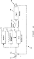
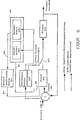
System zur Abstimmung eines Prozessregelkreises, wobei das System folgendes aufweist: – ein Abstimmungsmodul (600) zum Empfangen eines Fehlersignals (680), das für die Differenz zwischen einem Sollwert und einer Prozessvariablen repräsentativ ist, um mindestens ein erstes Prozesssteuersignal zur Regelung des Prozesses (630) zu erzeugen; – ein nicht lineares Modul (660) zur Erzeugung mindestens eines Parametersignals (651); – ein Reglermodul (610) zum Empfangen des Fehlersignals und des mindestens einen Parametersignals vom nicht linearen Modul (660), wobei das Reglermodul (610) ein zweites Prozesssteuersignal zur Regelung des Prozesses erzeugt; und – eine Schalteinrichtung (670), die mit dem Prozess gekoppelt ist, um entweder das Abstimmungsmodul (600) oder das Reglermodul (610) mit dem Prozess zu koppeln, um das erste oder zweite Prozesssteuersignal zur Regelung des Prozesses auszuwählen, dadurch gekennzeichnet, dass das Abstimmungsmodul (600) anhand des Fehlersignals (680) einen Satz charakteristischer Signale der wenigstens eine Grenzverstärkung Ku, Grenzperiodendauer Tu, Totzeit L...A system for tuning a process control loop, the system comprising: - a tuning module (600) for receiving an error signal (680), which is representative of the difference between a setpoint value and a process variable, for at least a first process control signal for regulating the process (630 ) to create; - A non-linear module (660) for generating at least one parameter signal (651); - a regulator module (610) for receiving the error signal and the at least one parameter signal from the non-linear module (660), the regulator module (610) generating a second process control signal for regulating the process; and - switching means (670) coupled to the process for coupling either the tuning module (600) or the controller module (610) to the process to select the first or second process control signal for regulating the process, characterized in that the tuning module (600) based on the error signal (680) a set of characteristic signals of the at least one limit gain Ku, limit period Tu, dead time L ...
Description
HINTERGRUND DER ERFINDUNGBACKGROUND OF THE INVENTION
Anwendungsbereich der ErfindungScope of the invention
Die vorliegende Erfindung betrifft ein System und ein Verfahren zur Abstimmung eines Prozessreglers basierend auf nicht linearen Schätzern der Abstimmungsregeln einschließlich neuronaler Netzwerke und Fuzzy-Logik.The present invention relates to a system and method for tuning a process controller based on non-linear estimators of voting rules including neural networks and fuzzy logic.
Beschreibung des Standes der TechnikDescription of the Prior Art
Ein Proportional-, Integral-, Differential-(PID)-Regler ist ein Regler, der allgemein für industrielle Prozesse, einschließlich computergesteuerter industrieller Prozesse, verwendet wird. Derartige PID-Regler und ihre Variationen und Kombinationen, beispielsweise P, PI, PD, erfreuen sich breiter Anwendung in der Regelung industrieller Prozesse. Typische industrielle Prozesse werden von einem oder mehreren Regelkreisen mit PID-Reglern geregelt.A proportional, integral, derivative (PID) controller is a controller commonly used in industrial processes, including computer-controlled industrial processes. Such PID controllers and their variations and combinations, for example P, PI, PD, are widely used in the control of industrial processes. Typical industrial processes are governed by one or more control loops with PID controllers.
Ein Fuzzy-Logik-Regler (Fuzzy Logic Controller – FLC) ist ebenfalls ein bekannter Prozessregler, der zur Regelung von Prozessparametern dient, indem Prozessvariablen innerhalb von mit gewünschten Sollwerten in Beziehung stehenden Parametern gehalten werden. FLC's sind nicht lineare Regler und werden in industriellen Umgebungen in verstärktem Maße eingesetzt.A Fuzzy Logic Controller (FLC) is also a well known process controller used to control process parameters by keeping process variables within parameters related to desired setpoints. FLCs are not linear regulators and are increasingly used in industrial environments.
Ein Typ bekannter Verfahren zur Abstimmung von Parametern eines PID-Reglers ist die Ziegler-Nichols-Methode. Die automatische Abstimmung basierend auf von einem Relais angeregten Schwingungen ist ebenfalls eine hinreichend bekannte und anerkannte Technik der automatischen Abstimmung. Die automatische Relaisschwingungsabstimmung bestimmt die Grenzverstärkung (Ultimate Gain) und die Grenzperiodendauer eines Prozesses an der Stabilitätsgrenze (Ultimate Period). Die Einstellungen des PID-Reglers können aus diesen Parametern mittels der Regeln von Ziegler-Nichols und Modifikationen davon bestimmt werden. Eine Weiterführung der Relaisschwingungsabstimmung, die über die Bestimmung der Grenzverstärkung und Grenzperiodendauer hinausgeht, wird in ”System and Method for Automatically Tuning a Process Controller”,
In den letzten Jahren wurden erhebliche Fortschritte auf dem Gebiet der modellbasierten Abstimmung, insbesondere mit der Internal Model Control-(IMC) und Lambda-Abstimmung erzielt. Beide Ansätze resultieren in einer Antwort eines geschlossenen Regelkreises erster Ordnung entsprechend den Änderungen der Sollwerte. Ein mit der Antwortgeschwindigkeit in Beziehung stehender Abstimmungsparameter wird verwendet, um den Kompromiss zwischen Leistung und Robustheit einzustellen. Mit beiden Verfahren werden der Integralzeitparameter des PID Reglers (oder der Integralzeitparameter und der Differentialzeitparameter) angepasst, um die Polstelle(n) des Prozesses zu eliminieren und die Reglerverstärkung so einzustellen, dass die gewünschte Antwort des geschlossenen Regelkreises erzielt wird. IMC- und Lambda-Abstimmung haben sich durchgesetzt, da Schwingungen und Übersteuern vermieden werden und das Regelverhalten über die Zeitkonstante des geschlossenen Regelkreises auf eine intuitive Weise vorgegeben werden kann.Significant progress has been made in recent years in the field of model-based tuning, in particular with Internal Model Control (IMC) and Lambda tuning. Both approaches result in a closed loop response of the first order corresponding to the changes in the setpoints. An answer speed related tuning parameter is used to set the trade-off between performance and robustness. Both methods adjust the integral time parameter of the PID controller (or the integral time parameter and the derivative time parameter) to eliminate the pole (s) of the process and adjust the controller gain to achieve the desired closed loop response. IMC and lambda tuning have prevailed as oscillations and oversteer are avoided and the control behavior can be preset in an intuitive way via the closed-loop time constant.
Eine der Grenzen der modellbasierten Abstimmung ist die Notwendigkeit der Bestimmung eines Prozessmodells. Ein äquivalentes Prozessmodell erster Ordnung plus Totzeit mit den Parametern statische Verstärkung, scheinbare Totzeit und scheinbare Zeitkonstante wird normalerweise für selbstregelnde Prozesse bestimmt. Für Prozesse mit integrierendem Verhalten werden Modellparameter der Integralverstärkung des Prozesses und der Totzeit bestimmt. Die Bestimmung des Modells erfolgt typischerweise mittels eines Sprungtests des offenen Regelkreises. Verglichen mit dem Verfahren der von einem Relais angeregten Schwingung lassen sich Verfahren für offene Regelkreise nicht leicht automatisieren. Bei Verfahren mit offenem Regelkreis sind aufgrund von Nichtlinearitäten des Prozesses, Ventilhysterese und Laststörungen häufig Eingriffe seitens eines Menschen erforderlich, um die Genauigkeit eines Modells sicherzustellen. Für selbstregelnde und Prozesse mit integrierendem Verhalten ist eine andere Technik erforderlich.One of the limitations of model-based tuning is the need to determine a process model. An equivalent first order process plus dead time with the parameters static gain, apparent dead time and apparent time constant is normally determined for self-regulating processes. For processes with integrating behavior, model parameters of the integral gain of the process and the dead time are determined. The determination of the model is typically done by means of a jump test of the open loop. Compared to the method of oscillation excited by a relay, open loop methods are not easily automated. In open-loop methods, non-linearities of the process, valve hysteresis, and load disturbances often require human intervention to ensure the accuracy of a model. Self-regulating and integrating behavior processes require a different technique.
Aus einem Aufsatz von Swinarzky (SWINIARSKI, R. W.: Novel Neural Network based Self-Tuning PID Controller Which Uses Pattern Recognition Technique. IN: American Control Conference, 1990, S. 3023–3024) ist es bekannt, ein neuronales Netz zu verwenden, um Parameter für die Ziegler-Nichols-Methode zu erzeugen. Des Weiteren geht es aus dieser Druckschrift hervor, dass man ein künstliches neuronales Netz, insbesondere ein aufgeschaltetes neuronales Netz, verwenden kann, um die Parameter für einen PID-Regler zu berechnen. Hierbei wird ein Prozess über einen längeren Zeitraum überwacht und daraus entsprechende Parameter für den PID-Regler abgeleitet. Dieses Verfahren ist sehr aufwändig.From an article by Swinarzky (SWINIARSKI, RW: Novel Neural Network-based Self-Tuning PID Controller Which Uses Pattern Recognition Technique., IN: American Control Conference, 1990, pp. 3023- 3024), it is known to use a neural network to generate parameters for the Ziegler-Nichols method. Furthermore, it is apparent from this document that one can use an artificial neural network, in particular a switched neural network, to calculate the parameters for a PID controller. Here, a process is monitored over a longer period of time and derived corresponding parameters for the PID controller. This process is very complicated.
Erforderlich sind ein System und ein Verfahren für die Abstimmung in einer Relaisschwingungsumgebung, die die erforderlichen PID-Abstimmungsparameter über alle Bereiche der Modellparameter bereitstellen und Modellparameter eines Prozesses bestimmen.What is needed is a system and method for tuning in a relay vibration environment that provide the required PID tuning parameters across all ranges of model parameters and determine model parameters of a process.
ZUSAMMENFASSUNG DER ERFINDUNGSUMMARY OF THE INVENTION
Diese Aufgabe wird durch ein System gemäß dem Anspruch 1 gelöst. Weitere vorteilhafte Ausführungsformen ergeben sich aus den Unteransprüchen.This object is achieved by a system according to
Das bereitgestellte System verwendet nicht lineare Ansätze im nicht linearen Modul zur Annäherung der gewünschten Abstimmungsparameter des Reglers. Die nicht linearen Ansätze umfassen die Abstimmung mittels neuronaler Netzwerke, die Abstimmung mittels Fuzzy-Logik und nicht linearen Funktionen, einschließlich der sigmoiden Abstimmung.The provided system uses non-linear approaches in the non-linear module to approximate the desired tuning parameters of the controller. The non-linear approaches include neural network tuning, fuzzy logic tuning and non-linear tuning, including sigmoid tuning.
Ein System sieht außerdem vor, dass das nicht lineare Modul nicht lineare Ansätze verwendet, um die gewünschten Parameter des Prozessmodells anzunähern. Gemäß einer Ausführungsform der vorliegenden Erfindung wird die Bestimmung eines Prozessmodells mittels neuronaler Netzwerke, Fuzzy-Logik und nicht linearen Funktionen einschließlich sigmoider Abstimmung erreicht, womit auf vorteilhafte Weise bessere Modellparameter erreicht werden können als mit den dem Stand der Technik entsprechenden analytischen Formeln für die Bestimmung auf Basis von durch ein Relais angeregten Schwingungen.One system also provides that the non-linear module uses nonlinear approaches to approximate the desired parameters of the process model. According to an embodiment of the present invention, the determination of a process model is achieved by means of neural networks, fuzzy logic and non-linear functions including sigmoid tuning, which can advantageously achieve better model parameters than the state-of-the-art analytical formulas for the determination Base of vibrations excited by a relay.
KURZE BESCHREIBUNG DER ZEICHNUNGENBRIEF DESCRIPTION OF THE DRAWINGS
Die vorliegende Erfindung und ihre zahlreichen Aufgaben, Merkmale und Vorteile wird für den Fachmann anhand der Beschreibung der beiliegenden Zeichnungen noch deutlicher.The present invention and its numerous objects, features and advantages will become more apparent to those skilled in the art from the description of the accompanying drawings.
Durch die Verwendung identischer Bezugszeichen in verschiedenen Zeichnungen werden ähnliche oder identische Elemente gekennzeichnet.By using identical reference numerals in different drawings, similar or identical elements are identified.
BESCHREIBUNG DES DER BEVORZUGTEN AUSFÜHRUNGSFORM(EN)DESCRIPTION OF THE PREFERRED EMBODIMENT (S)
Nunmehr sei auf
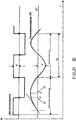
Die scheinbare Totzeit Td wird bei der Initialisierung der Abstimmung bestimmt. Die scheinbare Totzeit Td wird bestimmt, indem eine Tangente als Neigung des Prozessausgangs PV
Totzeit, Grenzverstärkung und Grenzperiodendauer sind zur Berechnung eines Prozessmodells erster Ordnung plus Totzeit ausreichend. Gleichungen (1) und (2) zur Berechnung der ersten Ordnung plus Totzeit lauten: 
- Tc
- = Zeitkonstante des Prozesses
- Tu
- = Grenzperiodendauer
- Td
- = scheinbare Totzeit des Prozesses
- Ks
- = statische Verstärkung des Prozesses
- Ku
- = Grenzverstärkung.
- T c
- = Time constant of the process
- T u
- = Boundary period
- T d
- = apparent dead time of the process
- K s
- = static amplification of the process
- K u
- = Limit gain.
Die Zeitkonstante des Prozesses in Gleichung (1) wird von einer Tangensfunktion ausgedrückt, die eine gute Näherung für die Argumente kleiner als π/3 liefert, wenn die Totzeit im Vergleich zur Zeitkonstanten relativ groß ist. Für Prozesse mit unerheblicher Totzeit ergibt sich bei der Berechnung der Zeitkonstanten ein großer Fehler, selbst bei einem kleinen Fehler in der Angabe der Totzeit (das Tangensargument ist annähernd gleich π/2, und ein kleiner Fehler im Argument führt zu einem großen Fehler des Tangenswertes). Eine gewisse Verbesserung ergibt sich durch die Verwendung einer linearen Funktion wie in Gleichung (3) dargestellt für Argumente größer als π/3: ![]()
![]()
Ziegler-Nichols-(ZN)-Regeln für die Abstimmung eines PID-ReglersZiegler-Nichols (ZN) rules for tuning a PID controller
Die Abstimmung basierend auf von einem Relais angeregten Schwingungen entspricht auf natürliche Weise den ZN-Regeln und liefert die Grenzverstärkung Ku und die Grenzperiodendauer Tu. Die ursprünglichen ZN-Formeln für PI-Regler lauten wie folgt:
Diese Formeln ergeben eine Phasenreserve, die zwischen etwa 20° und 90° stark schwankt, je nach dem Verhältnis τ der Totzeit L des Prozesses zur Zeitkonstanten T des Prozesses. Folglich variiert auch das Verhalten erheblich, nämlich von einer extrem schwingenden Antwort bei einem Prozess mit einem Verhältnis nahe 0,1 zu einer extrem trägen Antwort bei einem Prozess mit einem Verhältnis nahe 1,0.These formulas yield a phase margin that varies widely between about 20 ° and 90 °, depending on the ratio τ of the dead time L of the process to the time constant T of the process. Consequently, the behavior also varies considerably, from an extremely oscillatory response in a process with a ratio close to 0.1 to an extremely sluggish response in a process with a ratio near 1.0.
Ein PID-Regler, der mit den ursprünglichen ZN-Regeln
Die obige Modifikation verbessert das Verhalten von Regelkreisen mit τ nahe 0,5; Regelkreise mit kleinen Werten von τ werden jedoch sogar noch stärker schwingend.The above modification improves the behavior of control loops with τ close to 0.5; However, control loops with small values of τ become even more vibrating.
Andere, flexiblere Formeln (4), (5) und (6) liefern für den Entwurf der Phasen-/Verstärkungsreserve folgendes: ![]()
- α
- Entwurfsauswahl des Verhältnisses Td:Ti
mit dem Standardwert 0,15. - Gm
- gewünschte Verstärkungsreserve
mit dem Standardwert - ϕ
- Phasenreserve.
- K, Td und Ti
- sind die Parameter des Reglers.
- α
- Draft selection of the ratio T d : T i with the default value 0.15.
- G m
- desired gain reserve with default 2.0.
- φ
- Phase margin.
- K, T d and T i
- are the parameters of the controller.
Mit einer vorgegebenen Phasen- und Verstärkungsreserve liefert die Formel (7) konstante Koeffizienten, um Ti, Td und K aus Tu und Ku zu berechen. Ein typischer Entwurf mit ϕ = 45° ergibt folgende Koeffizienten:
Dieser Entwurf eignet sich für kleine τ, ergibt aber ein extrem träges Antwortverhalten für τ größer als 0,2.This design is suitable for small τ, but gives an extremely sluggish response for τ greater than 0.2.
Wird angenommen, dass die Phasenreserve ϕ = 33° und die Verstärkungsreserve = 3,0 betragen, dann resultieren folgende Koeffizienten in Formel (8):
Diese Koeffizienten eignen sich für den Entwurf eines schmalen τ-Bereichs in der Nähe von 0,25.These coefficients are suitable for designing a narrow τ region near 0.25.
Eine weitere bekannte Modifikation sieht die Definition von Reglerparametern als Funktionen der normalisierten Totzeit
Nicht lineare Schätzer der AbstimmungsregelnNon-linear estimator of voting rules
Bei der Entwicklung nicht linearer Schätzer von Abstimmungsregeln sind bestimmte Annahmen und Überlegungen zu berücksichtigen. Erstens werden sämtliche Eingangsparameter während des Relais-Schwingungstests gewonnen (d. h. die Grenzverstärkung, die Grenzperiodendauer und die Totzeit). Zweitens besteht der größte Mangel der Ziegler-Nichols-Regel in einer unangepassten Integralzeit des Reglers bei Prozessen mit geringer Totzeit und einer übermäßigen Integralzeit bei Prozessen mit erheblicher Totzeit. Drittens sollten die Abstimmungsregeln Abstimmungsparameter und Antworten des Reglers erbringen, die denen der modellgestützten Abstimmung (IMC oder Lambda) nahe kommen.When developing non-linear estimators of voting rules, certain assumptions and considerations should be considered. First, all input parameters are obtained during the relay oscillation test (i.e., the threshold gain, the threshold period, and the dead time). Second, the major shortcoming of the Ziegler-Nichols rule is an unadjusted integral time of the controller in processes of low dead time and excessive integral time in processes of significant dead time. Third, the voting rules should provide controller tuning parameters and responses that are close to those of model-based voting (IMC or lambda).
Der in
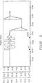
Ein sigmoider Ausdruck liefert einen glatten Übergang zwischen zwei verschiedenen Werten und dient zur Entwicklung nicht linearer Schätzer. Die folgenden Formeln erfüllen die obigen Anforderungen: 
a1 liegt zwischen 0,3 und 0,4;
b1 ≈ 0,6; b2 ≈ 1,0; c1 ≈ 7,0; c2 ≈ 4,0; d1 ≈ 0,125; d2 ≈ 1,0.A sigmoid expression provides a smooth transition between two different values and serves to develop non-linear estimators. The following formulas meet the above requirements:
a1 is between 0.3 and 0.4;
b1 ≈ 0.6; b2 ≈ 1.0; c1 ≈ 7.0; c2 ≈ 4.0; d1 ≈ 0.125; d2 ≈ 1.0.
Formel (10) ergibt den Wert des zur Berechnung von Ti verwendeten Koeffizienten, der zwischen einem Minimalwert von a1 und einem Maximalwert a1 + b1 schwankt, wie in
Dieser Ansatz resultiert in deutlich verbesserten Abstimmungsantworten, die denen der IMC- oder Lambda-Abstimmung nahe kommen (anders als dem Abklingen von ZN-Viertelamplituden). Einige typische Sprungantworten für verschiedene L/T sind in
Das Abstimmungssystem basierend auf Relaisschwingungen
Ein Entwurf der Abstimmeinrichtung gemäß den neuen nicht linearen Ansätzen der vorliegenden Erfindung gestattet es einem Anwender, das Abstimmungsverhalten anzupassen, indem die Wahlmöglichkeiten Slow (langsam), Normal (normal) und Fast (schnell) vorgesehen werden.
Nunmehr sei auf
Wie die Ausführungsform nach
Wie später beschrieben wird, ist der Schalter
Das erste Parametersignal
Das vom Reglerentwurf
Alternativ ist der analytische Reglerentwurf
Auf neuronale Netzwerke gestützte AbstimmungNeural network based voting
Unter Bezugnahme auf
Ähnlich der Eigenschwingungsprozedur, die in Zusammenhang mit
Die Prozedur zur Entwicklung neuronaler Netzwerktechniken beinhaltet einige grundlegende Schritte, die in
Das oben unter Bezugnahme auf ![]()
![]()
Das neuronale Netzwerk wird selektiv mit mehreren Ausgängen (Ausgänge K und Ti für das neuronale Netzwerk des Reglers und Kp und T für das neuronale Netzwerk des Modells) oder als mehrere neuronale Netzwerke mit einem einzigen Ausgang angewendet. Der Vorteil des neuronalen Netzwerks mit einem Ausgang ist die raschere Schulung. Aus diesem Grund implementiert eine Ausführungsform ein neuronales Netzwerk mit einem einzigen Ausgang. Bei einem beispielhaften Konzept für eine Abstimmungseinrichtung sind folgende Ein- und Ausgänge des neuronalen Netzwerks definiert:
Eingänge: Tu, Ku, L, Rauschpegel, Relaishysterese und Abtastgeschwindigkeit.The neural network is selectively applied with multiple outputs (outputs K and T i for the neural network of the controller and K p and T for the neural network of the model) or as multiple neural networks with a single output. The benefit of the single-output neural network is faster training. For this reason, one embodiment implements a neural network with a single output. In an exemplary concept for a voting device, the following inputs and outputs of the neural network are defined:
Inputs: T u , K u , L, noise level, relay hysteresis and sampling speed.
Tu, Ku, L und der Rauschpegel werden während des Abstimmungstests definiert.T u, u K, L, and the noise level are defined during the tuning test.
Die Relaishysterese und die Abtastgeschwindigkeit sind Parameter der Abstimmungseinrichtung.
Ausgänge: K, Ti, Td, Kp und T.The relay hysteresis and the sampling rate are parameters of the tuner.
Outputs: K, T i , T d , K p and T.
K, Ti und Td sind Parameter des PID-Reglers.K, T i and T d are parameters of the PID controller.
Kp und T gemeinsam mit L sind Parameter des Prozessmodells erster Ordnung plus Totzeit.K p and T together with L are parameters of the first order process model plus dead time.
Fragen der Implementierung und TestergebnisseQuestions of implementation and test results
Bei einem Beispiel der neuen nicht linearen Verfahren werden neuronale Netzwerkmodelle implementiert, um die automatische Abstimmungseinrichtung (Autotuner) auf Basis von durch ein Relais angeregten Schwingungen in einem skalierbaren Reglersystem für industrielle Zwecke zu verbessern. Der Autotuner weist zwei Blöcke auf: den Tunerfunktionsblock, der im Regler implementiert ist, und die Anwendung der Abstimmungseinrichtung. Die Anwendung der Abstimmungseinrichtung ist in einer geeigneten Konsole implementiert. Die neuronalen Netzmodelle werden zur Anwendung der Abstimmungseinrichtung hinzugefügt. Bei einer Ausführungsform sind die neuronalen Netzwerkmodelle für den Anwender der Abstimmungseinrichtung transparent, wobei der Autotuner keine zu neuronalen Netzwerken gehörigen Wahlmöglichkeiten oder Einstellungen aufweist.In one example of the new non-linear techniques, neural network models are implemented to enhance the autotuner based on relay-excited oscillations in a scalable controller system for industrial purposes. The autotuner has two blocks: the tuner function block implemented in the controller and the tuner application. The application of the voting device is implemented in a suitable console. The neural network models are added to the voting device application. In one embodiment, the neural network models are transparent to the user of the tuner, the autotuner having no choices or settings associated with neural networks.
Gemäß des hier beschriebenen Verfahrens wird das neuronale Netzwerk für das Prozessmodell zweiter Ordnung plus Totzeit geschult. Die nachstehende Spezifikation definiert die verfügbaren Eingangs- und Ausgangsdaten zur Schulung neuronaler Netzmodelle:According to the method described here, the neural network is trained for the second order process model plus dead time. The following specification defines the available input and output data for training neural network models:
Prozessmodell auf Basis eines neuronalen Netzes Process model based on a neural network
- Eingänge: Grenzverstärkung Ku, Grenzperiodendauer Tu und Totzeit L, definiert während des relaisbasierten Abstimmungsexperiments.Inputs: limit gain K u , limit period T u and dead time L, defined during the relay-based tuning experiment.
-
Ausgänge: Prozessverstärkung: 0,5; 1,0; 1,5; Zeitkonstante 1 des Prozesses in Sekunden: 1,0; 2,0; 5,0; 10,0; 20,0; 50,0; 100,0; 200,0; Zeitkonstante 2 des Prozesses in Sekunden: 1,0; 2,0; 5,0; 10,0; Totzeit in Sekunden: 1,0; 2,0; 5,0; 10,0; 20,0; 50,0; 100,0; 200,0.Outputs: process gain: 0.5; 1.0; 1.5;
Time constant 1 of the process in seconds: 1.0; 2.0; 5.0; 10.0; 20.0; 50.0; 100.0; 200.0;Time constant 2 of the process in seconds: 1.0; 2.0; 5.0; 10.0; Dead time in seconds: 1.0; 2.0; 5.0; 10.0; 20.0; 50.0; 100.0; 200.0.
Reglermodell auf Basis eines neuronalen NetzesController model based on a neural network
- Eingänge: wie für das Prozessmodel auf Basis eines neuronalen Netzwerkes.Inputs: as for the process model based on a neural network.
-
Ausgänge: Verstärkung K des PID-Reglers, Integralzeit Ti und Differentialzeit Td, berechnet aus den oben angegebenen Prozessmodellparametern für die Ausgänge, d. h. Prozessverstärkung 0,5; 1,0; 1,5; Zeitkonstante 1 des Prozesses in Sekunden: 1,0; 2,0; 5,0; 10,0; 20,0; 50,0; 100,0; 200,0; Zeitkonstante 2 des Prozesses in Sekunden: 1,0; 2,0; 5,0; 10,0; Totzeit in Sekunden: 1,0; 2,0; 5,0; 10,0; 20,0; 50,0; 100,0; 200,0.Outputs: gain K of the PID controller, integral time T i and derivative time T d , calculated from the process model parameters given above for the outputs, ie process gain 0.5; 1.0; 1.5;
Time constant 1 of the process in seconds: 1.0; 2.0; 5.0; 10.0; 20.0; 50.0; 100.0; 200.0;Time constant 2 of the process in seconds: 1.0; 2.0; 5.0; 10.0; Dead time in seconds: 1.0; 2.0; 5.0; 10.0; 20.0; 50.0; 100.0; 200.0.
Experimentelle ErprobungExperimental testing
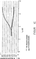
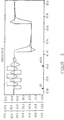
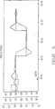
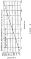
Eine experimentelle Erprobung der Abstimmungssimulierung wurde 142 mal durchlaufen, wobei es sich in etwa um die Mindestanzahl von Abtastungen handelt, die zur Schulung eines einfachen neuronalen Netzes geeignet sind. Die Abtastungen ergaben einen guten Korrelationskoeffizienten und im allgemeinen Werte des vorhergesagten Ausgangs, die den des erforderlichen Ausgangs nahe kamen. Die Graphen der Ergebnisse für Ti sind in
Bei manchen Intervallen des vorhergesagten Parameterbereichs war der Vorhersagefehler nicht akzeptabel. Diesbezüglich gibt es zwei spezifische Fälle. In einem Fall handelt es sich um kleine Werte der vorhergesagten Reglerparameter (relativ zum Vorhersagefehler). In diesem Fall ergibt sogar ein vorhergesagter Parameter von nur 1% des maximalen Wertes nicht akzeptable Parameter. Wie insbesondere aus
Eine andere Fehlersituation tritt ein, wenn im Unterbereich zu wenig Abtastungen enthalten sind. Möchte beispielsweise ein Anwender den Bereich der neuronalen Netzmodellierung erweitern, indem für einen erweiterten Unterbereich, z. B. Ti > 50,0 in
Auf einem neuronalen Netzwerk basierende AbstimmungsregelnNeural network based voting rules
Um Anomalien zu vermeiden, wenden die Abstimmungsmodelle auf Basis neuronaler Netze gemäß den beispielhaften, nicht linearen Techniken folgende Regeln bzw. Schritte an. Erstens sind so viele Abtastungen wie möglich zu erfassen. Es ist zumindest die Mindestanzahl Abtastungen zu erfassen, die für ein einfaches Modell erforderlich sind. Zweitens ist der Bereich für den vorhergesagten Parameter so zu wählen, dass sich ein innerhalb des Bereichs liegender Parameter nur wenige Male (ca. 5) ändert. Ändern sich die vorhergesagten Werte öfters (ca. 15 mal), ist der Bereich der Parameteränderungen auf mehrere Unterbereiche aufzuteilen, und es sind mehrere neuronale Netzmodelle zu entwickeln. Drittens sind kleine vorhergesagte Werte mit besonderer Aufmerksamkeit zu behandeln. Sind die vorhergesagten Werte im Vergleich zum Vorhersagefehler klein, ist für die kleinen Werte ein getrenntes neuronales Netzmodell zu erstellen.To avoid anomalies, the neural network tuning models employ the following rules, in accordance with the example non-linear techniques. First, as many samples as possible should be captured. At a minimum, it is necessary to capture the minimum number of samples required for a simple model. Second, the range for the predicted parameter should be chosen such that an in-range parameter changes only a few times (about 5). If the predicted values change more frequently (about 15 times), the range of parameter changes has to be divided into several subregions, and several neural network models have to be developed. Third, small predicted values should be given special attention. If the predicted values are small compared to the prediction error, a separate neural network model has to be created for the small values.
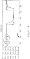
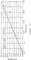
Beispielsweise wurde ein Modell mit einem eingeengten Unterbereich von 15 bis 33 (anstelle von 1 bis 320 des vollen Bereich) entwickelt. Obwohl die Anzahl der Abtastungen unter der Mindestanzahl lag, war die Vorhersage viel besser als beim ursprünglichen Modell für den gesamten Bereich. Ein Graph der Vorhersage des neuronalen Netzmodells für den Unterbereich von Ti ist in
Lineare und nicht lineare Korrekturfunktionen zur Bestimmung des ProzessmodellsLinear and non-linear correction functions for determining the process model
Nunmehr sei erneut auf
Die aus Formeln (1) und (3) erzeugte Zeitkonstante (Tc) ist erheblich kleiner für kleinere Verhältnisse scheinbarer Totzeit des Prozesses zur Grenzverstärkung![]()
![]()
![]()
![]()

Eine Korrekturfunktion f(Tu/Td), angewendet auf die angegebene Zeitkonstante des Prozesses
Eine einfache lineare Funktion mit Koeffizienten, die aus simulierten Tests entwickelt wurden, korrigiert die Zeitkonstante des Prozesses gemäß Gleichung (12): 
Bei einer nicht linearen Funktion sorgt ein sigmoider Ausdruck für einen glatten Übergang zwischen zwei unterschiedlichen Werten. Eine sigmoide Korrekturfunktion ist hinreichend gut definiert, wenn die minimalen und maximalen Werte bekannt sind. Die folgende Formel (13) für die Schätzung der Zeitkonstanten des Prozesses wurde auf Basis einer kleiner Menge simulierter Daten entwickelt: 
Formel 12 ergibt den Wert des für die Berechnung von Tc verwendeten Koeffizienten, der zwischen einem minimalen Wert von 0,8 und einem maximalen Wert von 2,2 variiert Nach der Korrektur der Zeitkonstanten wird die statische Verstärkung des Prozesses erneut unter Anwendung der Formel (2) berechnet, die nachstehend wiederholt wird: 
Die Abstimmungs- und Berechnungsergebnisse für den Prozess mit der statischen Verstärkung 1,0 sind in Tab. 1 und mit der statischen Verstärkung 2,0 in Tabelle 2 zusammengestellt. In beiden Fällen ist der Prozess als Modell zweiter Ordnung mit T1 = 10 s; T2 = 2 s plus Totzeit gemäß Spalte Td modelliert. Der Bezeichner näherte das Modell um ein Modell erster Ordnung plus Totzeit an (Td bestimmt). Die dargestellten Modellparameter werden zunächst angegeben (Td, Kp und Tc) und mittels linearer und nicht linearer Schätzungsformeln (Kp und Tc) korrigiert.
Die Anwendung beider Korrekturfunktionen verbesserte die Bestimmung des Prozessmodells erheblich.The application of both correction functions considerably improved the determination of the process model.
Fuzzy-Logik-gestützte BestimmungFuzzy logic-based determination
Ein typischer Fuzzy-Logik-Regler ist ein nicht linearer Reglertyp. Einzigartige Merkmale eines Fuzzy-Logik-Reglers sind die Funktionsweise und die Entwicklung des Reglers. Ein Fuzzy-Regelalgorithmus wird durch linguistische Regeln definiert. Die Reglereingangsparameter werden durch Fuzzy-Mengen repräsentiert. Die Funktionsweise des Reglers wird durch die Regeloberfläche, insbesondere bei Reglern, die Eingangsparameter verwenden, gut dargestellt.A typical fuzzy logic controller is a non-linear controller type. Unique features of a fuzzy logic controller are the operation and development of the controller. A fuzzy rule algorithm is defined by linguistic rules. The controller input parameters are represented by fuzzy sets. The operation of the controller is well represented by the control surface, especially with controllers that use input parameters.
Die Prozedur zur Entwicklung von Fuzzy-Logik-(FL)-Funktionen ist ähnlich der Prozedur zur Entwicklung eines Fuzzy-Logik-Reglers. Das nachstehende Verfahren dient zur Bestimmung einer FL-Korrekturfunktion. Die Regelung von Prozessen mittels Fuzzy-Logik ist allgemein bekannt (vgl. Kahlert, Jörg: Fuzzy-Control für Ingenieure, ISBN 3-528-05460-3).The procedure for developing fuzzy logic (FL) functions is similar to the procedure for developing a fuzzy logic controller. The following procedure is for determining a FL correction function. The regulation of processes by means of fuzzy logic is generally known (see Kahlert, Jörg: Fuzzy Control for Engineers, ISBN 3-528-05460-3).
Erstens wird angenommen, dass die Korrekturfunktion für die Zeitkonstante des Prozessmodells folgende Form hat:
Zweitens ist die Funktion mit zwei Argumenten zu verwenden, wobei das Verhältnis Tu/Td das erste und die Grenzverstärkung das zweite Argument ist.Second, the function is to use two arguments, where the ratio Tu / Td is the first and the bounds gain is the second argument.
![]()
![]()
Es ist möglich, verschieden viele und verschiedene Typen Zugehörigkeitsfunktionen zu verwenden. Der einfachen Implementierung wegen sind einfache Dreieck-Zugehörigkeitsfunktionen für die Eingangsparameter und Singleton-Funktionen für die Ausgangssignale zu verwenden.
Eine Defuzzifizierung des Ausgangssignals ist für Singleton-Zugehörigkeitsfunktionen zutreffend.
Experimentelle Ergebnisse der Fuzzy-Logik-SimulierungExperimental results of fuzzy logic simulation
Die Fuzzy-logische Korrekturfunktion ergab Zeitkonstanten und Verstärkungsschätzungen, die vergleichbar mit den Schätzungen mittels linearer und nicht linearer Korrekturfunktionen sind.The fuzzy logic correction function yielded time constants and gain estimates comparable to the estimates using linear and non-linear correction functions.
Gemäß Tabelle 4 liefert ein auf Relaisschwingungen basierender Bezeichner mit hinzugefügten Korrekturfunktionen ein Modell erster Ordnung. plus Totzeit, das für modellgestützte Abstimmungsberechnungen eines PID-Reglers verwendet werden kann.According to Table 4, a relay vibration based identifier with added correction functions provides a first order model. plus dead time, which can be used for model-based tuning calculations of a PID controller.
Sowohl nicht lineare Funktionen als auch neuronale Netzmodelle verbessern die Abstimmungsregeln auf Basis von durch ein Relais angeregten Schwingungen erheblich. Unter Einhaltung der vorgegebenen Grundsätze in der Entwicklung der Abstimmung basierend auf neuronalen Netzen liefert die Modellierung neuronaler Netzwerke eine Reihe von Vorteilen. Ein Anwender kann beliebige Abstimmungsregeln (nicht notwendigerweise Lambda oder IMC) implementieren und zur Entwicklung von auf neuronalen Netzen basierenden Abstimmungsmodellen die gleiche Methodik anwenden. Ein in der Simulierung entwickeltes neuronales Netzmodell kann bestimmte Merkmale des Abstimmungsentwurfs aufnehmen. Abtastgeschwindigkeit und Rauschpegel, die den Entwurf des Reglers beeinflussen, lassen sich auf einfache Weise als Eingangsparameter zur Vorhersage hinzufügen.Both non-linear functions and neural network models significantly improve voting rules based on relay-excited oscillations. Adhering to the established principles in the development of neural network tuning, neural network modeling provides a number of advantages. A user may implement arbitrary voting rules (not necessarily lambda or IMC) and apply the same methodology to develop neural network based voting models. A neural network model developed in the simulation can accommodate certain features of the voting design. Sampling speed and noise levels, which influence the design of the controller, can be easily added as input parameters to the prediction.
Andere AusführungsformenOther embodiments
Obwohl die hierin beschriebenen Systeme und Verfahren eine Abstimmungseinrichtung verwenden, die die Grenzperiodendauer und die Grenzverstärkung eines Prozesses berechnet, um Informationen zu entwickeln, kann jeder andere Typ Abstimmungseinrichtung, der Prozesskennwerte misst, verwendet werden, einschließlich Abstimmungseinrichtungen mit offenem Regelkreis und andere Abstimmungseinrichtungen mit geschlossenem Regelkreis. Des weiteren können die mittels der offenbarten Systeme und Verfahren bestimmten Faktoren und Steuerparameter entweder von einem Anwender oder automatisch eingegeben werden.Although the systems and methods described herein employ a tuner that calculates the cutoff period and limit gain of a process to develop information, any other type of tuner that measures process characteristics may be used, including closed loop tuners and other closed loop tuners , Furthermore, the factors and control parameters determined by the disclosed systems and methods may be input either by a user or automatically.
Des weiteren können die in allen schematischen Blockdiagrammen hierin bezeichneten Elemente hardwaremäßig verwirklicht oder in einem geeignet programmierten digitalen Rechner oder Prozessor, der mit Software – entweder in Form getrennter Programme oder als Module eines gemeinsamen Programmes – programmiert ist, implementiert werden.Furthermore, the elements referred to in all of the schematic block diagrams herein may be implemented in hardware or implemented in a suitably programmed digital computer or processor programmed with software, either in the form of separate programs or as modules of a common program.
Claims (9)
Applications Claiming Priority (2)
| Application Number | Priority Date | Filing Date | Title |
|---|---|---|---|
| US15032399P | 1999-08-23 | 1999-08-23 | |
| US150323 | 1999-08-23 |
Publications (2)
| Publication Number | Publication Date |
|---|---|
| DE10041439A1 DE10041439A1 (en) | 2001-03-01 |
| DE10041439B4 true DE10041439B4 (en) | 2011-08-11 |
Family
ID=22534037
Family Applications (1)
| Application Number | Title | Priority Date | Filing Date |
|---|---|---|---|
| DE2000141439 Expired - Lifetime DE10041439B4 (en) | 1999-08-23 | 2000-08-23 | Automatic tuning device for a loop based on non-linear estimators of tuning rules |
Country Status (3)
| Country | Link |
|---|---|
| JP (1) | JP3512376B2 (en) |
| DE (1) | DE10041439B4 (en) |
| GB (1) | GB2353608B (en) |
Families Citing this family (4)
| Publication number | Priority date | Publication date | Assignee | Title |
|---|---|---|---|---|
| DE112009005510A5 (en) * | 2008-01-31 | 2013-06-20 | Fisher-Rosemount Systems, Inc. | Robust adaptive model predictive controller with tuning to compensate for model mismatch |
| CN102331717A (en) * | 2011-10-10 | 2012-01-25 | 哈尔滨工程大学 | Intelligent control method of navigational speed of ship |
| KR101478450B1 (en) | 2013-07-19 | 2014-12-31 | 재단법인대구경북과학기술원 | Design method of variable pid gains for multivariable nonlinear systems |
| US11467543B2 (en) | 2019-09-20 | 2022-10-11 | Fisher-Rosemount Systems, Inc. | Process controller design with process approximation and lambda tuning |
Citations (2)
| Publication number | Priority date | Publication date | Assignee | Title |
|---|---|---|---|---|
| US5453925A (en) * | 1993-05-28 | 1995-09-26 | Fisher Controls International, Inc. | System and method for automatically tuning a process controller |
| DE19748718A1 (en) * | 1997-11-05 | 1999-05-06 | Hans Werner Dr Ing Philippsen | Self-adjusting device for process control system |
Family Cites Families (3)
| Publication number | Priority date | Publication date | Assignee | Title |
|---|---|---|---|---|
| SE447608B (en) * | 1985-04-03 | 1986-11-24 | Hightech Network Ab | PROCEDURE AND DEVICE FOR SETTING A DIGITAL REGULATOR |
| JPS6266301A (en) * | 1985-09-18 | 1987-03-25 | Yamatake Honeywell Co Ltd | Auto tuning controller |
| US5742503A (en) * | 1996-03-25 | 1998-04-21 | National Science Council | Use of saturation relay feedback in PID controller tuning |
-
2000
- 2000-08-22 GB GB0020529A patent/GB2353608B/en not_active Expired - Lifetime
- 2000-08-23 JP JP2000252805A patent/JP3512376B2/en not_active Expired - Lifetime
- 2000-08-23 DE DE2000141439 patent/DE10041439B4/en not_active Expired - Lifetime
Patent Citations (2)
| Publication number | Priority date | Publication date | Assignee | Title |
|---|---|---|---|---|
| US5453925A (en) * | 1993-05-28 | 1995-09-26 | Fisher Controls International, Inc. | System and method for automatically tuning a process controller |
| DE19748718A1 (en) * | 1997-11-05 | 1999-05-06 | Hans Werner Dr Ing Philippsen | Self-adjusting device for process control system |
Non-Patent Citations (4)
| Title |
|---|
| ABE, N., SEKI, K., KANOH, H.: Internal Model Control for Single Tubular Heat Exchanger System. In: IECON '94, 20th International Conference on Industrial Electronics, 1996, S. 1165-1170 * |
| HANG, C.C., ASTRÖM, K.J., HO, W.K.: Refinements of the Ziegler- Nichols tuning formula. In: IEE Proceedings-D, Vol. 138, Nr. 2, 1991, S. 111-118 * |
| KAHLERT, J.: Fuzzy-Control für Ingenieure, Vieweg Verlagsgesellschaft, 1995, ISBN 3-528-05460-3 * |
| SWINIARSKI, R.W.: Novel Neural Network based Self-Tuning PID Controller Which Uses Pattern Recognition Technique. In: American Control Conference, 1990, S. 3023-3024 * |
Also Published As
| Publication number | Publication date |
|---|---|
| GB0020529D0 (en) | 2000-10-11 |
| GB2353608A (en) | 2001-02-28 |
| DE10041439A1 (en) | 2001-03-01 |
| JP2001100803A (en) | 2001-04-13 |
| GB2353608B (en) | 2003-10-08 |
| JP3512376B2 (en) | 2004-03-29 |
Similar Documents
| Publication | Publication Date | Title |
|---|---|---|
| DE69123026T2 (en) | Setting device with self-monitoring for a controller with feedback | |
| DE102004019352B4 (en) | State-based adaptive feedback / feedforward PID controller (PID control unit) | |
| DE102006045429B4 (en) | Adaptive, Model Predictive Online control in a process control system | |
| DE10196372B3 (en) | Adaptive feedback / feedforward PID controller | |
| DE102004058238B4 (en) | Adaptive, multivariable process control that uses model switching and attribute interpolation | |
| DE10012258B4 (en) | Self-tuning in a distributed process control environment | |
| DE69823049T2 (en) | MODEL-FREE ADAPTIVE PROCESS CONTROL | |
| EP2185980B1 (en) | Method for computer-aided control and/or regulation using neural networks | |
| DE69434487T2 (en) | METHOD AND DEVICE FOR FUZZY LOGIC CONTROL WITH AUTOMATIC TUNING PROCESS | |
| DE69122313T2 (en) | Adaptive control based on a variable horizon with means for minimizing operating costs | |
| DE10127788B4 (en) | Integrated optimal model predictive control in a process control system | |
| DE69219167T2 (en) | Control method for voltage or reactive power and control device therefor | |
| DE102004026979B4 (en) | Multiple input / multiple output control blocks with non-linear prediction capabilities | |
| DE69909838T2 (en) | CONTROL UNITS FOR SETTING OPTIMAL PARAMETERS IN PROCESS CONTROL SYSTEMS AND METHODS FOR APPLYING THE SAME | |
| DE10231417A1 (en) | Model-free adaptive process regulator system has tuning device with amplification adaptation assembly and assembly for monitoring process variable to determine if process variable oscillates | |
| DE3650164T2 (en) | Process controller with a system for setting with two degrees of freedom. | |
| DE69535702T2 (en) | Control device for heating element | |
| DE10341764A1 (en) | Integrated model prediction control and optimization within a process control system | |
| DE60107630T2 (en) | Self-adjusting method and system for a controller | |
| DE10341573A1 (en) | Integrated model-based predictive control and optimization within a process control system | |
| DE10341574A1 (en) | Configuration and viewing display for an integrated predictive model control and optimization function block | |
| DE4035099A1 (en) | OVEN TEMPERATURE CONTROL DEVICE WITH ONE ADJUSTING INPUT | |
| EP0663632A1 (en) | Method and apparatus for controlling a process | |
| DE10392599T5 (en) | Method for controlling a target system | |
| DE4240984A1 (en) |
Legal Events
| Date | Code | Title | Description |
|---|---|---|---|
| 8110 | Request for examination paragraph 44 | ||
| R018 | Grant decision by examination section/examining division | ||
| R020 | Patent grant now final |
Effective date: 20111112 |
|
| R071 | Expiry of right |