CN87100586A - The rotary joint device of use in pressurized fluid line - Google Patents
The rotary joint device of use in pressurized fluid line Download PDFInfo
- Publication number
- CN87100586A CN87100586A CN198787100586A CN87100586A CN87100586A CN 87100586 A CN87100586 A CN 87100586A CN 198787100586 A CN198787100586 A CN 198787100586A CN 87100586 A CN87100586 A CN 87100586A CN 87100586 A CN87100586 A CN 87100586A
- Authority
- CN
- China
- Prior art keywords
- pipeline
- sealing
- joint
- pipeline portions
- portions
- Prior art date
- Legal status (The legal status is an assumption and is not a legal conclusion. Google has not performed a legal analysis and makes no representation as to the accuracy of the status listed.)
- Pending
Links
Images
Classifications
-
- F—MECHANICAL ENGINEERING; LIGHTING; HEATING; WEAPONS; BLASTING
- F16—ENGINEERING ELEMENTS AND UNITS; GENERAL MEASURES FOR PRODUCING AND MAINTAINING EFFECTIVE FUNCTIONING OF MACHINES OR INSTALLATIONS; THERMAL INSULATION IN GENERAL
- F16J—PISTONS; CYLINDERS; SEALINGS
- F16J15/00—Sealings
- F16J15/02—Sealings between relatively-stationary surfaces
-
- F—MECHANICAL ENGINEERING; LIGHTING; HEATING; WEAPONS; BLASTING
- F16—ENGINEERING ELEMENTS AND UNITS; GENERAL MEASURES FOR PRODUCING AND MAINTAINING EFFECTIVE FUNCTIONING OF MACHINES OR INSTALLATIONS; THERMAL INSULATION IN GENERAL
- F16L—PIPES; JOINTS OR FITTINGS FOR PIPES; SUPPORTS FOR PIPES, CABLES OR PROTECTIVE TUBING; MEANS FOR THERMAL INSULATION IN GENERAL
- F16L27/00—Adjustable joints, Joints allowing movement
- F16L27/08—Adjustable joints, Joints allowing movement allowing adjustment or movement only about the axis of one pipe
- F16L27/0804—Adjustable joints, Joints allowing movement allowing adjustment or movement only about the axis of one pipe the fluid passing axially from one joint element to another
- F16L27/0808—Adjustable joints, Joints allowing movement allowing adjustment or movement only about the axis of one pipe the fluid passing axially from one joint element to another the joint elements extending coaxially for some distance from their point of separation
- F16L27/0824—Adjustable joints, Joints allowing movement allowing adjustment or movement only about the axis of one pipe the fluid passing axially from one joint element to another the joint elements extending coaxially for some distance from their point of separation with ball or roller bearings
- F16L27/0832—Adjustable joints, Joints allowing movement allowing adjustment or movement only about the axis of one pipe the fluid passing axially from one joint element to another the joint elements extending coaxially for some distance from their point of separation with ball or roller bearings having axial bearings
Abstract
Be used for the particularly swivel joint of high pressure high flow rate pipeline of pressurized fluid line, the first and second close parts in the pipeline are kept concentric and unconnected state mutually and form an axial joint between two-part, first portion can be rotated with respect to second portion around its own axis.Comprise that also a device is used for two pipeline portions are supported in concentric and unconnected state mutually; Tubular seal is placed pipeline and trans-axial joint with one heart, between two close parts and joint and directly contact with them, so that the place of being tightly connected and allow the fluid in the pipeline flow to another part from a part internally.
Description
The present invention is about being used for the rotary joint device of pressurized fluid line, the piecing devices in particularly a kind of fluid circuit that is used for high pressure (above 10,000 pounds/square inch) high flow rate.
Can pivot with respect to concentric another part for a part that makes pressurized fluid line, a kind of a kind of joint between two-part just need be provided, and the device that seals this joint.A kind of device that is implemented in this connection under the high pressure high flow rate in the prior art is to utilize a large diameter axle, and it is comprising joint, and the Sealing that is wrapping joint around the external diameter of axle.Yet the device that is found such can cause high apparent surface's speed between the part of axle and the Sealing, thereby produces heat, and heat can exceed the heat-resisting scope of Sealing, and then its is damaged.In addition, this pattern needs quite high driving torque to come the axle of a part is rotated with respect to another part, a big cover supports high interior pressure, and huge axial force (this is to suppose only to have used a Sealing, but is not the swivel joint of two Sealings thereby balancing axial thrust) that big bearing comes supporting axle.
A kind of problems such as heat that said method causes and high moment of torsion that reduce have reduced the measure of swivel joint boundary dimension simultaneously again significantly, are that Sealing is placed fluid circuit, as U. S. Patent 2,421,974(Fan Defu invention) shown in.Can see this two-part fluid circuit is set to mutually with one heart, form axially connection between the two, the sealed eyelet that in pipeline, has a combination to fill, it is across the joint, yet, what pay particular attention to is that this extension between joint and filling sealing of metal ring is crossed the joint, clear illustrating in Fig. 2 of this patent.Seal action require this metal ring particularly its external diameter have accurate size.Annular space between two holes of this ring and the joint that matches should be very little so that the protrusion of Sealing can not take place.Consequently whole swivel joint can only be worked under quite low loine pressure.Particularly when U. S. Patent 2,421, swivel joint in 974 is under the sufficiently high situation of interior pressure, this metal ring will outwards be out of shape, protrusion enters between the joint of two pipeline portions, is contacting the hole wall of two mating parts, causes very large friction, thereby hinder the spinning movement of joint significantly, and joint can not be rotated.
Since top described, therefore an object of the present invention is to provide a kind of swivel joint, and it does not have above-mentioned the sort of Sealing to be contained in the heating and the big shortcoming of moment of torsion of the joint of outside, and is specially adapted to the use occasion of high pressure high flow rate.
Another object of the present invention provides a kind of swivel joint, and it uses an interior dress Sealing that crosses the joint, enters the joint even depress sealing part protrusion in height, and joint can also arbitrarily rotate.
Another purpose of the present invention provides a kind of the sort of swivel joint of mentioning just now, and the concentricity between its two-part is improved, and the beat degree dwindles.
A further object of the present invention provides a kind of swivel joint, and it uses a pipeline inner seal liner to be placed in two-part, no matter whether Sealing rotates, can not kill rotation or non-rotary part.
Another one purpose of the present invention provides a kind of swivel joint, and it has a pipeline inner seal liner, and it is made into and reduces under high loine pressure to protrude the possibility that enters the joint.
A further object of the invention provides a kind of device that mentioned just now, and its Sealing is made axial section, so that reduce to cross the pipeline inner pressure loss of joint to it after being placed in the pipeline.
The present invention still has a purpose to provide a kind of swivel joint, and it comprises a pipeline inner seal liner along a row bearing, and it is made into can easily change Sealing and do not hinder each bearing.
The present invention more has a purpose to provide a kind of swivel joint, and it comprises a pipeline inner seal liner, and it is made into allows Sealing easily insert the working position, more effectively utilizes the fluid that flows through this device to cool off this Sealing simultaneously.
An other purpose of the present invention provides a kind of swivel joint, and it comprises a pipeline inner seal liner that crosses the joint, and it is made into any axial clearance of eliminating the joint.
As following to carefully say, swivel joint disclosed herein uses the first and second two close parts of pressurized fluid line, they are concentric, but do not connect together each other, thereby the axial connection between formation two-part, first portion can rotate with respect to second portion around its axis.This joint also has device to be used for being supported in first and second parts of pipeline concentric mutually but unconnected state, the Sealing of a tubulose is arranged in the axial joint of crossing in the fluid circuit between adjacent two-part with one heart, seal this joint internally, but allow the interior fluid of pipeline lead to another part from a part.
According to a feature of the present invention, this tubular seal is to make with the sealing material one, and it has sealing and bearing (low friction) performance, for example makes with polytetrafluoroethylene.Like this, the Sealing that directly contacts with the joint not only sealed but also provide bearing surface of quite low friction is provided for this.In addition,, thereby protrude into the joint between two pipeline portions, also can not influence the sealing of crossing the joint or the rotary moveable between adjacent two-part if the interior pressure in the pipeline makes its produce radial and outward deformation.
According to another feature of the present invention, the axial section of sealing part is big in the part near the joint than any side outside this part, thereby has strengthened the sealing part to press the radially outward that causes to protrude in the axial connection in the opposing pipeline.The axial section of Sealing has in this embodiment preferably formed a Venturi tube that crosses the joint, and direction is consistent with the fluid flow direction by pipeline, thereby has reduced any pressure drop of crossing the joint.
According to another feature of the present invention, Sealing stretches into first pipeline portions ratio and stretches into second pipeline portions for long, so it can rotate together around its axis and first pipeline portions, and does not need to be fixed in the first portion.On the other hand, if desired, Sealing can be arranged to stretch into second pipeline portions ratio and stretch into first pipeline portions length, makes it not follow first pipeline portions to rotate together, does not equally also need Sealing is fixed on its position.
According to another feature of the present invention, the single radial bearing that first and second parts of making whole joint are enclosed within their external diameters with one heart by and cover the joint between them is supported in concentric mutually but unconnected state.This just helps to increase the concentricity between two-part and reduces the beat degree.
According to another one feature of the present invention, the part of pipeline is divided at least two branches again, and the bearing of one of the branch and the whole joint of getting along well forms part and cooperates.This special branch can easily throw off from another, so that Sealing is removed from its working position.Like this, the replacement Sealing just can not influence the bearing arrangement in the whole piecing devices.
Remaining purpose of the present invention and feature can become clear by detailed description with reference to the accompanying drawings, wherein:
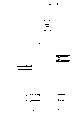
Fig. 1 is according to the axial section of the swivel joint that has the pipeline inner seal liner of one embodiment of the invention design;
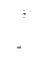
Fig. 2 has simply represented when leakage or has not had the pressure distribution of crossing the pipeline inner seal liner under the leakage situation;
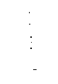
Fig. 3,4 and 5 has simply represented the pipeline inner seal liner according to three different embodiment's designs of the present invention;
Fig. 6,7,8 and 9 has represented that briefly some are according to other the axial section of swivel joint of embodiment's design of the present invention;
Figure 10 has simply represented to have designed according to this invention the axial section of the pipe inner seal liner and the swivel joint of seat, has eliminated any gap of whole device joint;
Figure 11 A is that the seat that installs among Figure 10 forms side view partly, and this seat is designed to hydrostatic equilibrium;
Figure 11 B is the end elevation of the seat shown in Figure 11 A;
Figure 12 is used for one improved the side view that Figure 10 installs.
See Fig. 1 earlier, it illustrates swivel joint 10 designed according to this invention.Whole device is specially adapted to the high pressure occasion, and it comprises two close first portions 12 and second portion 14, after they are assembled on the working position, forms the part of whole pressurized fluid line (not demonstrating).The supportive device 16 that will say below forms the part of whole device, being used for a part 12 and 14 is supported in mutually discrete concentric, to form an axial joint 18 between two-part, like this, at least one of in two-part, for example part 12, can be around its axis with respect to another part, for example part 14, rotation.As shown in Figure 1, pipeline portions 12 and 14 two not opposite end 20 and 22 are shaped on outside thread, so they can be screwed in the internal thread that matches of pipeline end and are connected in (not shown) in the whole pipeline.Like this, fluid can flow to another part from a part under pressure, as shown in arrow 25.
In the embodiment shown in fig. 1, supportive device 16 is designed to support this two pipeline portions 12 and 14, the rotation of having only part 12 to do with respect to part 14.Should be noted that supportive device also can be made makes any part rotate with respect to another part.Remember this point, illustrated supportive device comprises a main coupling 26, and its two ends 28 and 30 are shaped on internal thread and hold outside thread end plug 32 and 34 separately.Joiner and end plug are arranged to one heart round pipeline portions 12 and 14 and joint 18, as shown in the figure.According to a viewpoint of the present invention, a single cylindrical shape radial bearing 36 is arranged to around the outside that also directly contacts the adjacent part 12 of pipeline two-phase and 14, and trans-axial joint 18, so that supporting pipeline portions 12 works are with respect to the rotation of part 14.Because two pipeline portions are crossed in the position of radial bearing 36, so help to improve the concentricity of two pipeline portions and reduce the beat degree of pipeline portions 12 when its axis is done rotation with respect to part 14.
Outside above-mentioned element, whole supportive device 16 also comprises a pair of low pressure sealing ring that axially splits 38, the both sides of their joints 18 between pipeline portions 12 and 14 and a radial bearing 36.The effect of low pressure sealing ring 38 is that foreign object is not entered on the bearing surface.Equally, give loading and thrust bearing 46 and 48 placed separately shown in the position, arrange along radial bearing 36, the whole bearing arrangement of a supporting pipeline portions 12 rotations is provided.Because pipeline portions 14 is not designed to rotate, so do not equip same loading and the thrust bearing of giving.Yet, should be understood that they also can be equipped with, so that allow pipeline portions 14 rotations.
Outside above-mentioned element, whole device 10 also comprises a Sealing 50.The sealing part is shown as the single piece that a kind of material is made in Fig. 1, this material not only can provide the sealing of crossing joint 18, also can on the bearing surface between sealing and one of pipeline portions 12 or 14, produce relative low friction, as for being that part 12 or part 14 will see whom is in rotation and sealing itself to be rotation or fixing and fixed actually.A kind of material that can meet two kinds of conditions saying just now is polytetrafluoroethylenes, also mentioned above, though also have other materials also to be suitable for, for example nylon or your woods (delrin), but be not limited to these.
The purposes of Sealing 50 is the places 18 that are tightly connected, and allows one of two pipeline portions with respect to another rotation simultaneously.Simultaneously, in order to reduce to cross the pressure drop of joint.Therefore, Sealing preferably place the whole fluid bearings passage 54 that forms by pipeline portions 12 and 14 expansion axial component 52, do like this, the internal diameter of Sealing 50 is substantially equal to the diameter of passage 54 at least.
A noticeable feature of Sealing 50 is that the most handy a kind of material is made, a kind of during this material quote from above for example, and it will radial and outward deformation and protrude into joint 18 and can not be cracked because of high relatively loine pressure.Pressure in Sealing is increased to a degree and makes its distortion and partly protrude into joint 18, and the rotatory power of joint can not have significant harmful effect.This is because the projection of Sealing can not play bearing surface, and as in contrast, for example, the metal ring in No. 2,421,974, the U. S. application of saying above is such.
This deformability of Sealing 50 also helps to eliminate the leakage along the seal outer surface generation between channel part 52 and gap 18.This clear being illustrated among Fig. 2 with the pressure characteristic in 56 and 58 Sealings of representing 50 and pipeline portions 12 and 14 surface of contact.Pressure characteristic 56 expressions are when there not being the pressure that crosses sealing contact surface when leaking.Pressure characteristic 58 is corresponding to the pressure that crosses sealing contact surface when leaking.The gun pressure that each characteristic curve is all expressed in the Sealing 50 trends towards making the sealing material radial and outward deformation, has therefore filled up the space, has stoped any leakage, thereby has sealed the space.
Another of Sealing 50 is noticeable to be characterised in that it can be placed in the channel part 52, uses no matter whether it rotates can both start to control to make.This clearly draws in Fig. 2, the Sealing at this place be painted as stretch in the pipeline portions 12 longer than stretching in the pipeline portions 14.In other words, it seems that it is right-hand far away that Sealing is stretched than to the gap to the left in gap 18 from Fig. 2.Discord pipeline portions 14 is maintained fixed because this position relation between Sealing and two pipeline portions, Sealing trend towards and then pipeline portions 12 rotations, though Sealing is not fixed on the pipeline portions 12.This is that hypothesis Sealing and two pipeline pipeline portions cooperate degree of tightness roughly the same.If Sealing is set in pipeline portions 14 than long in the pipeline portions 12, when pipeline portions 12 rotated, Sealing will heel part 14 be maintained fixed together.Opposite with these two kinds of extreme cases is if Sealing stretches into two pipeline portions with equal length, unless Sealing is fixed on one of two pipeline portions, just cannot predict that it can or can not and then rotate.About this point, we do not wish Sealing is fixed on the pipeline portions, can make Sealing be difficult to take out when needs are changed because do like this.Simultaneously, whether the rotation of prediction Sealing also is very important, and this has is convenient to select suitably it will rotate the material of contact (or material rotation contact seal part), so that reduce friction between the two.For example, if known seal is done the rotation with respect to pipeline portions 14, the material of making this pipeline portions can be selected for use suitably to have suitable bearing surface and comes the contact seal part.
As mentioned above, under high relatively loine pressure, Sealing 50 can protrude into axial joint 18.Prevent that a kind of method that this situation takes place from being that the section configuration that designs Sealing makes it thicker than all the other two ends in the joint.In a preferential embodiment, be that seal designs one-tenth is reached at the direction formation Venturi tube that fluid flows through passage 54, as the Sealing among Fig. 3 60.The additional advantage of this measure is owing to have the wake flow that recovers pressure, and the pressure drop of crossing joint 18 is reduced.In Fig. 4 and Fig. 5, demonstrate similar Sealing shape 62 and 64 separately.Shape 62 comprises an outmost cylindrical seal 66 of being made by suitable sealing and bearing material, for example uses commaterial with part 50.Yet this shape also comprises internals 68, and it is harder or have more rigidity than part 66, and it needn't have sealing or bearing ability.Would rather this part 68 be to be used for preventing that internal duct pressure from protruding into joint 18 to Sealing 66.Part 68 also can have the axial section of Venturi tube to reduce to cross the pressure drop of joint 18.Shape 64 is similar in appearance to shape 62, and it also comprises a Sealing 70 and the reinforcer 72 with the axial section of Venturi tube.Yet part 72 extends axially a side that exceeds Sealing 70.Because whole shape 64 and pipeline portions 12 rotate together, part 72 needn't have the bearing ability.
The attendant advantages of the sealing inserting member among Fig. 4 and Fig. 5 is that the part separately 68 or 72 among Fig. 4 and Fig. 5 can both be reused.The Sealing 66 or 72 that only is simple cylindrical shape need be changed after their spreadable life.
From the above, be noted that Sealing 60 and shape 62 and shape 64 have square end to face toward the angled ends of Sealing 50.About this point, should be understood that the present invention is not limited to square end or angled ends, but any above that said or the following Sealing that will say can comprise one of positive square end or angled ends or both.Equally, the Sealing of the piecing devices that all are narrated form other part all can put into a pipeline portions than another pipeline portions for long, should be appreciated that the present invention is not limited to these shapes.In other words, in described embodiment, it is equally long that each Sealing can be placed on the both sides of joint separately.In addition,, also can have other axial section though each described embodiment comprises a Sealing with special shaft to section, comprise Fig. 2 to the section shown in Figure 5 any one.
Remember top argumentation, refer now to Fig. 6, it has shown a rotary joint device 74 by another embodiment of the present invention design.Device 74 comprises concentric and unconnected pipeline portions 76 and 80, and they form 82, one pipeline inner seal liners in a joint 84 together and extend and cross the joint.These pipeline portions and Sealing with above the part 12 said the same with 14 and Sealing 50, part 76 and Sealing 84 are with respect to part 80 rotations.For this purpose, this device comprises radially and thrust bearing 86 and 88, is arranged in separately between two pipeline portions, as shown in Figure 6.
The place that whole device 74 is different from said apparatus 10 is that pipeline portions 80 is made into and Sealing 84 can be easily removed from its working position pack into and do not influence bearing 86 and 88.For this purpose, pipeline portions 80 is made up of two branches 90 and 92, and they are detachably interconnecting by axial bolt or screw thread 94.Branch 90 is arranged to one heart round radial bearing 86 and axially heads on bearing 88, and branch's any bearing of 92 discord cooperates.Simultaneously, branch 92 is detachably connecting branch 90 so that Sealing 84 is come out and do not influence bearing 86 and 88.This allows when needed, and Sealing 84 can be touched easily and be changed and do not involved bearing.Low pressure sealing ring preferably is arranged between the branch 92 of pipeline portions 76 and pipeline portions 80, shown among Fig. 6 96, and between the branch 90 of pipeline portions 76 and pipeline portions 80, shown in 96a among Fig. 6.
Referring to Fig. 7, demonstrate another one rotary joint device 98 at this, it and above said device 74 are slightly different.Device 98 comprises that need make 100, one concentric unconnected pipeline portions of pipeline portions, 102, one cover bearings 104 and 106, one low pressure sealing rings 108 and the pipeline inner seal liner 110 of rotation.Pipeline portions 102 is made up of three branches, and first branch 112 is designed 104,106, two branches 114 of fitted bearing and 116 discord bearings to cooperate.Branch 114 detachably connects branch 112 by axial bolts or screw thread 118.Branch 116 is seats, and it is placed in the hole that matches of branch 114 to admit the end of Sealing 110, as shown in Figure 7.Sealing is placed in shown position,, stretches into pipeline portions 100 than stretching into 116 length that is, and Sealing is made into follows pipeline portions 100 to rotate together.If the passage 118 in the pipeline portions 100 has little or do not have beat, seat 116 can be made into unsteady so that obtain maximum concentricity.Otherwise seat is retained in the branch 114.No matter which kind of situation, seat 116 can easily be removed (or refilling) so that do not involve bearing 104 and 106 ground disassembling, assembling and replacing Sealings 110.The additional advantage of using seat 116 is that it can easily be made with abrasive-resistant material, for example tool steel, wolfram steel, titanium cemented carbide because of simple shape.
The whirligig 120 that Fig. 8 shows is similar with device 74 in many aspects.Particularly, device 120 comprises 122, one two pipeline portions 124 corresponding to two pipeline portions 80 of pipeline portions corresponding to pipeline portions 76, radial bearing 126 and thrust bearing 128, and a Sealing 130.Yet, at the radial bearing of device in 120 basically near its Sealing 130.Owing to make the Sealing of radial bearing, reduced beat near it.
In device 120, radial bearing 126 is installed in the part 124.
Referring to Fig. 9, the whirligig 130 that demonstrates is in many aspects similar in appearance to device 98.As device 98, device 130 comprises a rotation pipeline portions 132 corresponding to the pipeline portions 100 of device 98, many pipeline portions 134 corresponding to pipeline portions 102 are radially with thrust bearing 136 and 138, one low pressure sealing rings 140 and a Sealing 142.In addition, device 130 comprises a plug 144, and it is the part of many pipeline portions 134 and detachably is contained on the pipeline portions.Plug is removed, can not involved bearing or anyly be connected to the pipeline of whirligig 130 and Sealing 142 is easily changed.
In above-mentioned all devices, neither one comprises the aggressive device of eliminating any gap, axial joint, this profile though all above-mentioned devices have drawn, and except installing 10, its drawn gap at traverse points 18 places.Figure 10 device shown 146 comprises that reliable device is very close to each other in order to guarantee in its axial joint, will talk about below.
Translate into Figure 10, device 146 comprises a rotation pipeline portions 148 and unconnected concentric many pipeline portions 150.That pipeline portions of back comprises that one first 156(of branch is not shown) cooperating the bearing of necessity of piecing devices to form other part, one second branch 160 and one the 3rd branch 162.Branch 160 makes limited axial sliding movement with an end of supporting branch 162 as an end plug in the cavity 164 that matches.
The other end of branch 162 is used for holding an end of Sealing 166, and sealing part 166 is parts of whole device.The end face 168 of branch 162 is facing to the corresponding end face 170 of pipeline portions 148.Two facing surfaces 168,170 have formed the axial joint of device together.Below as can be seen, as the branch 162 of seat by axially to the direction pressurization of face 170 to eliminate the gap in any axial joint.
Referring to Figure 10, branch's seat 162 is shown by spring part 172 and axially presses to a left side again, and as shown in the figure, spring part 172 is set to one heart round the present big part in cavity 164 and the part of dwindling of filling in the seat between 160 the end face.Simultaneously, seat itself will be talked about below its reason because its structure shape by hydraulic static ground balance.
In order to paraphrase seat 162 is how by the hydraulic static balance, referring to Figure 11 A and 11B.In these figure, the right hand end of seat has an outside diameter d, and the left hand end has identical internal diameter.Remember this and notice the flow direction in the piecing devices be shown in the arrow among Figure 10 174 from right to left, the axial pressure at the present two ends of effect is identical opposite as can be seen, thereby causes the hydraulic static balance of seat.Referring to Figure 10, notice that seat is to prevent that with column cap screw 176 it from rotating around the axis of oneself again, this column cap screw 176 is placed in the matching hole of branch 156, and can match with the axially extended groove 178 on the seat 162.
Because seat is 162 by the hydraulic static balance, the spring force that is sent by spring part 172 will guarantee the contact gently between the apparent surface 168,170, and regardless of the loine pressure in the whole piecing devices how.This spring force will compensate because axial deviation that pressurization causes and gap increase.Need, spring chamber 164 can give pressurization to keep the two higher contact pressures that match between the surface with proper pressure.Also can make seat and have an interior Venturi tube to reduce pressure loss, improved seat 162 as shown in Figure 12 ' such.
Claims (17)
1, a kind of rotary joint device of use in pressurized fluid line is characterized by and comprises:
(a) first and second of this pipeline close parts, they mutually with one heart and keep unconnected state, thereby form an axially axial joint between the close end face of these two parts, it radially extends between the inside and outside surface of these two pipeline portions, and this first portion can rotate with respect to this second portion around its axis;
(b) have device to be used for this first and second pipeline portions is supported in this concentric and unconnected state, so that form this axial joint, this first portion can rotate with respect to this second portion around its oneself axis;
(c) a tubular Sealing is made with the material monolithic with sealing and bearing characteristics, it is placed this pipeline with one heart and is crossed this axial joint, the two end portions of sealing part directly contacts the internal surface of these two close pipeline portions separately, so that allow the fluid in the pipeline lead to another part and allow this first pipeline portions rotation from one of these two-part in this joint of inner sealing.
2, as the device in the claim 1, it is characterized by, the sealing part stretches into this first pipeline portions ratio, and to stretch into this second pipeline portions long, thereby cause Sealing to follow this first pipeline portions to rotate together around its axis and use less than Sealing is secured in this first portion.
3, as the device in the claim 2, it is characterized by, the sealing part has an axial section, its the specific part that is directly adjacent to this joint, than the specific part both sides that are in Sealing and thicker away from two parts of this joint, thereby strengthened Sealing, protrude into this axial joint with opposing because of the interior pressure radially outward in the pipeline.
4, as the device in the claim 2, it is characterized by, the sealing part forms the flow through Venturi tube that crosses this joint of this pipeline direction of a longshore current body.
5, as the device in the claim 1, it is characterized by, the sealing material is a polytetrafluoroethylene.
6, as the device in the claim 1, it is characterized by, also comprise a kind of device, it has more rigidity than sealing part, radially placed the sealing part, and directly contacted the sealing part to prevent that the sealing part is owing to the interior pressure in this pipeline protrudes into this axial joint.
7, as the device in the claim 6, it is characterized by, this harder device has an axial section, and it forms the flow through Venturi tube that crosses this joint of this pipeline direction of a longshore current body.
8, as the device in the claim 1, it is characterized by, this supportive device comprises a single tubular radial bearing, and it is set to the outside of the close part that centers on this first and second pipeline portions with one heart and centers on this joint.
9, as the device in the claim 1, it is characterized by, this supportive device comprises the bearing means that matches between the surface and directly contact with them that is arranged in this first and second pipeline portions, to allow this first pipeline portions rotate with respect to this second pipeline portions around its axis, it provides the surface of matching of this first portion and this second pipeline portions comprises one first branch, one second branch detachably connects this first branch, those branches be made into when this second branch when this first branch takes apart, just can move down the sealing part from device and do replacing and do not influence this bearing means.
10, as the device in the claim 9, it is characterized by, this second branch comprises two detachably attachment portions, have only one of them directly to contact with the sealing part, thereby a part of this second branch when another one part is taken apart, the sealing part is loaded onto from install pulled down.
11, as the device in the claim 10, it is characterized by, the sealing part is placed in this pipeline and rotates together with this first pipeline portions, wherein this part is being connected this another part, thereby the sealing part follows this first pipeline portions together with respect to this partial rotation, and this part can freely be made radial floating with respect to this another part in a limited range.
12, as the device in the claim 1, it is characterized by, this supportive device comprise one radially with an axial bearing arrangement, they are placed in the also directly contact with it between the face that matches of this first and second pipeline portions, so that allow this first pipe section rotate with respect to this second pipeline portions around its axis, this radial bearing device is set to than this axial bearing arrangement more axially near this joint.
13, as the device in the claim 1, it is characterized by, one of this pipeline portions comprises one first branch, one second branch radially places first branch also can move axially with respect to this first branch, spring assembly is being pressed this second branch along the direction of this first pipeline portions, this second branch is set to the sealing part and directly contacts, and have a circumferential surface that radially extends and this first pipeline portions match the surface vis-a-vis, therefore two surfaces of matching have formed this joint together, this spring assembly is used for the surface pressure that matches of this second branch to the surface of matching of this first pipeline portions, thereby has eliminated any gap between two surfaces.
14, as the device in the claim 13, it is characterized by, this second branch is made in this pipeline and compresses into capable hydraulic static balance.
15, a kind of rotary joint device of use in pressurized fluid line, this device comprises:
(a) first and second of this pipeline close parts, they mutually with one heart and keep unconnected state, thereby form an axially axial joint between the close end face of these two parts, it radially extends between the inside and outside surface of these two pipeline portions, and this first portion can rotate with respect to this second portion around its axis;
(b) have device to be used for this first and second pipeline portions is supported in this concentric and unconnected state, so that form this axial joint, this first portion can rotate with respect to this second portion around its oneself axis;
(c) a tubular Sealing is made with the material monolithic with sealing and bearing characteristics, it is placed this pipeline with one heart and is crossed this axial joint, the two end portions of sealing part directly contacts the internal surface of these two close pipeline portions separately, so that allow the fluid in the pipeline lead to another part in this joint of inner sealing from one of these two-part, the sealing part stretches into this first tubular portion ratio, and to stretch into this second portion long, thereby make Sealing follow this first pipeline portions to rotate around its axis and need not be secured to Sealing in this first portion.
16, a kind of rotary joint device of use in pressurized fluid line, this device comprises:
(a) first and second of this pipeline close parts, they mutually with one heart and keep unconnected state, thereby form the axial joint between two parts, this first portion can rotate with respect to this second portion around its axis;
(b) have device to be used for this first and second pipeline portions is supported in this concentric and unconnected state, so that form this axial joint, this first portion can rotate with respect to this second portion around its oneself axis;
(c) a tubular Sealing is placed this pipeline with one heart, and cross this and two allow the fluid in the pipeline lead to another part so that seal this joint internally from one of these two-part near this axial joint between the part, the sealing part stretches into this second pipeline portions ratio and stretches into this first portion head a bit, thereby makes Sealing can not follow this first pipeline portions rotation around its axis.
17, as the device in the claim 1, it is characterized by, the sealing part one of stretches in these two pipeline portions to be grown than another.
Applications Claiming Priority (2)
| Application Number | Priority Date | Filing Date | Title |
|---|---|---|---|
| US826,191 | 1986-02-05 | ||
| US06/826,191 US4669760A (en) | 1986-02-05 | 1986-02-05 | Swivel fitting arrangement for use in a pressurized fluid line |
Publications (1)
| Publication Number | Publication Date |
|---|---|
| CN87100586A true CN87100586A (en) | 1987-08-19 |
Family
ID=25245941
Family Applications (1)
| Application Number | Title | Priority Date | Filing Date |
|---|---|---|---|
| CN198787100586A Pending CN87100586A (en) | 1986-02-05 | 1987-02-02 | The rotary joint device of use in pressurized fluid line |
Country Status (7)
| Country | Link |
|---|---|
| US (1) | US4669760A (en) |
| EP (1) | EP0232178B1 (en) |
| JP (1) | JPS62196489A (en) |
| KR (1) | KR870008136A (en) |
| CN (1) | CN87100586A (en) |
| AT (1) | ATE53903T1 (en) |
| DE (1) | DE3762549D1 (en) |
Cited By (2)
| Publication number | Priority date | Publication date | Assignee | Title |
|---|---|---|---|---|
| CN106641524A (en) * | 2016-12-24 | 2017-05-10 | 北京工业大学 | Flange sectioning connection type rotary connector |
| CN113167420A (en) * | 2018-12-10 | 2021-07-23 | 国民油井华高英国有限公司 | Articulated flow line connector |
Families Citing this family (19)
| Publication number | Priority date | Publication date | Assignee | Title |
|---|---|---|---|---|
| US5454603A (en) * | 1993-10-22 | 1995-10-03 | Staley, Jr.; Colin R. | Co-axial hose coupling adapted for replacing inner hose upon rupture thereof and method therefor |
| AU4717896A (en) * | 1995-02-03 | 1996-08-21 | Artform International Limited | Connector |
| DE19932355B4 (en) * | 1999-07-10 | 2010-07-15 | GAT Gesellschaft für Antriebstechnik mbH | Rotary feedthrough for changing media |
| US6126524A (en) * | 1999-07-14 | 2000-10-03 | Shepherd; John D. | Apparatus for rapid repetitive motion of an ultra high pressure liquid stream |
| US6283832B1 (en) | 2000-07-18 | 2001-09-04 | John D. Shepherd | Surface treatment method with rapid repetitive motion of an ultra high pressure liquid stream |
| US6752685B2 (en) | 2001-04-11 | 2004-06-22 | Lai East Laser Applications, Inc. | Adaptive nozzle system for high-energy abrasive stream cutting |
| US6705921B1 (en) | 2002-09-09 | 2004-03-16 | John D. Shepherd | Method and apparatus for controlling cutting tool edge cut taper |
| US7717470B1 (en) * | 2003-08-13 | 2010-05-18 | Lockheed Martin Corporation | Quick fluid connector leakage containment |
| US7040959B1 (en) | 2004-01-20 | 2006-05-09 | Illumina, Inc. | Variable rate dispensing system for abrasive material and method thereof |
| JPWO2007043334A1 (en) * | 2005-10-07 | 2009-04-16 | トヨタ自動車株式会社 | Casing seal structure |
| JP2007232206A (en) * | 2006-02-01 | 2007-09-13 | Seiko Epson Corp | Tube with connector, and its shaping method |
| AU2007240098B2 (en) * | 2006-04-19 | 2011-08-18 | Taimi R & D Inc. | Multifunctionally swivelling coupling assembly for fluid lines |
| US7600460B2 (en) * | 2006-05-09 | 2009-10-13 | Stephen M. Manders | On-site land mine removal system |
| DE202008006612U1 (en) * | 2008-05-15 | 2008-08-07 | Parker Hannifin Gmbh & Co. Kg | Connection and connection device for high-pressure lines |
| DE202010016929U1 (en) | 2010-12-23 | 2011-02-24 | Parker Hannifin Gmbh | Turning and swivel connection for high pressure systems |
| US9067331B2 (en) | 2011-04-01 | 2015-06-30 | Omax Corporation | Waterjet cutting system fluid conduits and associated methods |
| US10260667B2 (en) * | 2016-01-26 | 2019-04-16 | Karl M. ATKINSON | Tamper-resistant frictionless connector assembly |
| US11002191B2 (en) * | 2019-01-04 | 2021-05-11 | Ge Aviation Systems Llc | Electric machine with non-contact interface |
| CN115698507A (en) | 2020-03-30 | 2023-02-03 | 海别得公司 | Cylinder for liquid injection pump with multifunctional interface longitudinal end |
Family Cites Families (23)
| Publication number | Priority date | Publication date | Assignee | Title |
|---|---|---|---|---|
| US537744A (en) * | 1895-04-16 | Hose-coupling | ||
| US1930833A (en) * | 1929-08-19 | 1933-10-17 | Eastman Mfg Co | Swiveling hose union |
| US1889980A (en) * | 1929-09-30 | 1932-12-06 | Service Equipment Company | Swiveled tire inflating chuck |
| US1951460A (en) * | 1930-04-22 | 1934-03-20 | Schraders Son Inc | Valve stem |
| US2362975A (en) * | 1942-07-13 | 1944-11-21 | Taine G Mcdougal | Hydraulic seal |
| US2416657A (en) * | 1944-02-29 | 1947-02-25 | Dunlop Rubber Co | Hose coupling |
| US2421974A (en) * | 1944-09-22 | 1947-06-10 | Parker Appliance Co | Swivel fitting |
| US2819935A (en) * | 1954-09-07 | 1958-01-14 | Oilgear Co | Seal for very high pressures |
| US3067777A (en) * | 1960-06-07 | 1962-12-11 | John F Briscoe | Packless flow swivel |
| US3211471A (en) * | 1961-04-14 | 1965-10-12 | Robert B Darlington | Fluid transfer gland |
| DE1267489B (en) * | 1965-02-24 | 1968-05-02 | Piv Antrieb Reimers Kg Werner | Device for introducing pressurized fluid into the free end of a rotating shaft from a component that does not touch it |
| CH441894A (en) * | 1966-10-17 | 1967-08-15 | Nussbaum & Co Ag R | Rotatable pipe connection |
| US3462174A (en) * | 1967-02-28 | 1969-08-19 | Ethyl Corp | Rotatable coupling |
| US3623751A (en) * | 1969-04-04 | 1971-11-30 | Clarence E Hulbert Jr | Swivel joint |
| DE2001228A1 (en) * | 1970-01-13 | 1971-07-22 | Jahndorf Helmut | Swivel joint with exchangeable inner lining |
| FR2133302A5 (en) * | 1971-04-09 | 1972-11-24 | Cordel & Cie | Bearing and seal - for swivel joint |
| US3877732A (en) * | 1972-09-28 | 1975-04-15 | Univ Waterloo | High pressure rotary coupling |
| US3913952A (en) * | 1974-01-23 | 1975-10-21 | Riken Seiki Kk | Rotary coupling for superhigh hydraulic pressure generating apparatus |
| US3957294A (en) * | 1974-06-06 | 1976-05-18 | The United States Of America As Represented By The Secretary Of The Navy | Rotary gas joint |
| US3997198A (en) * | 1975-02-27 | 1976-12-14 | Linder Morris B | Swivel joint construction for pressure containing conduit |
| US3967842A (en) * | 1975-09-22 | 1976-07-06 | Halliburton Company | High pressure tubular swivel joint |
| US4451364A (en) * | 1982-03-03 | 1984-05-29 | Brownlee Labs Inc. | High pressure seal and coupling |
| US4500119A (en) * | 1983-03-21 | 1985-02-19 | Geberth John Daniel Jun | Fluid swivel coupling |
-
1986
- 1986-02-05 US US06/826,191 patent/US4669760A/en not_active Expired - Fee Related
-
1987
- 1987-02-02 CN CN198787100586A patent/CN87100586A/en active Pending
- 1987-02-05 KR KR870000915A patent/KR870008136A/en not_active Application Discontinuation
- 1987-02-05 DE DE8787301039T patent/DE3762549D1/en not_active Expired - Fee Related
- 1987-02-05 JP JP62025545A patent/JPS62196489A/en active Pending
- 1987-02-05 EP EP87301039A patent/EP0232178B1/en not_active Expired - Lifetime
- 1987-02-05 AT AT87301039T patent/ATE53903T1/en not_active IP Right Cessation
Cited By (4)
| Publication number | Priority date | Publication date | Assignee | Title |
|---|---|---|---|---|
| CN106641524A (en) * | 2016-12-24 | 2017-05-10 | 北京工业大学 | Flange sectioning connection type rotary connector |
| CN106641524B (en) * | 2016-12-24 | 2018-10-09 | 北京工业大学 | A kind of subdivision flange join type rotary joint |
| CN113167420A (en) * | 2018-12-10 | 2021-07-23 | 国民油井华高英国有限公司 | Articulated flow line connector |
| US11506314B2 (en) | 2018-12-10 | 2022-11-22 | National Oilwell Varco Uk Limited | Articulating flow line connector |
Also Published As
| Publication number | Publication date |
|---|---|
| US4669760A (en) | 1987-06-02 |
| EP0232178A2 (en) | 1987-08-12 |
| JPS62196489A (en) | 1987-08-29 |
| ATE53903T1 (en) | 1990-06-15 |
| KR870008136A (en) | 1987-09-24 |
| EP0232178A3 (en) | 1987-11-04 |
| EP0232178B1 (en) | 1990-05-02 |
| DE3762549D1 (en) | 1990-06-07 |
Similar Documents
| Publication | Publication Date | Title |
|---|---|---|
| CN87100586A (en) | The rotary joint device of use in pressurized fluid line | |
| US6007105A (en) | Swivel seal assembly | |
| RU2179676C2 (en) | Power-operated end face sealing | |
| CN1014444B (en) | Oil seal with antirotation ribs | |
| CN85109414A (en) | Open the fraction mechanical end face seal | |
| RU2127376C1 (en) | Self-aligning shaft support | |
| US5490682A (en) | Split mechanical face seal | |
| CN1007374B (en) | Seal device | |
| JPS5848792B2 (en) | Conduit swivel joint | |
| US20040245728A1 (en) | Lip seal | |
| US4449739A (en) | Rotary coupling | |
| CA2366840C (en) | Self-aligning shaft support | |
| US5342065A (en) | Inflatable seal arrangement | |
| US4934744A (en) | Rotary joint for conveying feedwater | |
| EP0878271A2 (en) | A hydraulic nut | |
| KR100594821B1 (en) | Annular Seal, Especially for a Ball Valve | |
| US5176511A (en) | Seal structure for a rotating cam pressurized fluid device | |
| CN211202335U (en) | Turbocharger with sealing ring supercharging structure | |
| CN219034661U (en) | Top drive flushing pipe device of mechanical seal | |
| CN218992349U (en) | Combined structure silicon carbide mechanical sealing device | |
| CN214092430U (en) | Mechanical sealing equipment of centrifugal pump | |
| SU1016575A1 (en) | Sliding support | |
| GB2143605A (en) | Swivel joint | |
| AU2016219663B2 (en) | Air supply system for a drill rig | |
| RU2201528C2 (en) | Oil-well screw pump shaft seal |
Legal Events
| Date | Code | Title | Description |
|---|---|---|---|
| C06 | Publication | ||
| PB01 | Publication | ||
| C10 | Entry into substantive examination | ||
| SE01 | Entry into force of request for substantive examination | ||
| C01 | Deemed withdrawal of patent application (patent law 1993) | ||
| WD01 | Invention patent application deemed withdrawn after publication |