CN86103065B - Power transmitting apparatus for tractor - Google Patents
Power transmitting apparatus for tractor Download PDFInfo
- Publication number
- CN86103065B CN86103065B CN86103065A CN86103065A CN86103065B CN 86103065 B CN86103065 B CN 86103065B CN 86103065 A CN86103065 A CN 86103065A CN 86103065 A CN86103065 A CN 86103065A CN 86103065 B CN86103065 B CN 86103065B
- Authority
- CN
- China
- Prior art keywords
- clutch
- clutch end
- main
- travels
- shaft
- Prior art date
- Legal status (The legal status is an assumption and is not a legal conclusion. Google has not performed a legal analysis and makes no representation as to the accuracy of the status listed.)
- Expired
Links
Images


Classifications
-
- B—PERFORMING OPERATIONS; TRANSPORTING
- B60—VEHICLES IN GENERAL
- B60K—ARRANGEMENT OR MOUNTING OF PROPULSION UNITS OR OF TRANSMISSIONS IN VEHICLES; ARRANGEMENT OR MOUNTING OF PLURAL DIVERSE PRIME-MOVERS IN VEHICLES; AUXILIARY DRIVES FOR VEHICLES; INSTRUMENTATION OR DASHBOARDS FOR VEHICLES; ARRANGEMENTS IN CONNECTION WITH COOLING, AIR INTAKE, GAS EXHAUST OR FUEL SUPPLY OF PROPULSION UNITS IN VEHICLES
- B60K17/00—Arrangement or mounting of transmissions in vehicles
- B60K17/04—Arrangement or mounting of transmissions in vehicles characterised by arrangement, location, or kind of gearing
-
- B—PERFORMING OPERATIONS; TRANSPORTING
- B60—VEHICLES IN GENERAL
- B60K—ARRANGEMENT OR MOUNTING OF PROPULSION UNITS OR OF TRANSMISSIONS IN VEHICLES; ARRANGEMENT OR MOUNTING OF PLURAL DIVERSE PRIME-MOVERS IN VEHICLES; AUXILIARY DRIVES FOR VEHICLES; INSTRUMENTATION OR DASHBOARDS FOR VEHICLES; ARRANGEMENTS IN CONNECTION WITH COOLING, AIR INTAKE, GAS EXHAUST OR FUEL SUPPLY OF PROPULSION UNITS IN VEHICLES
- B60K17/00—Arrangement or mounting of transmissions in vehicles
- B60K17/28—Arrangement or mounting of transmissions in vehicles characterised by arrangement, location, or type of power take-off
-
- Y—GENERAL TAGGING OF NEW TECHNOLOGICAL DEVELOPMENTS; GENERAL TAGGING OF CROSS-SECTIONAL TECHNOLOGIES SPANNING OVER SEVERAL SECTIONS OF THE IPC; TECHNICAL SUBJECTS COVERED BY FORMER USPC CROSS-REFERENCE ART COLLECTIONS [XRACs] AND DIGESTS
- Y10—TECHNICAL SUBJECTS COVERED BY FORMER USPC
- Y10T—TECHNICAL SUBJECTS COVERED BY FORMER US CLASSIFICATION
- Y10T74/00—Machine element or mechanism
- Y10T74/19—Gearing
- Y10T74/19023—Plural power paths to and/or from gearing
- Y10T74/19074—Single drive plural driven
- Y10T74/19079—Parallel
Landscapes
- Engineering & Computer Science (AREA)
- Chemical & Material Sciences (AREA)
- Combustion & Propulsion (AREA)
- Transportation (AREA)
- Mechanical Engineering (AREA)
- Arrangement And Driving Of Transmission Devices (AREA)
- Arrangement Of Transmissions (AREA)
- General Details Of Gearings (AREA)
Abstract
A power transmitting apparatus for a tractor is provided, which includes a travel drive line and a PTO drive line. The travel drive line is operatively connected to an engine through a running-travel clutch whereas the PTO drive line is directly connected to the engine and includes thereon a PTO clutch. Thus the two drive lines are independent of each other in respect of power transmission and clutching operation.
Description
The relevant power transmitting apparatus for tractor of the present invention, the power transmitting apparatus for tractor with two driving systems, just driving transmission agent and clutch end (PTO) driving system.
In the drive apparatus of this existing pattern, driving transmission agent and clutch end driving system are accepted power from an axle, so these two systems can not be independent mutually.The disadvantage of this structure is found in aspects such as grass processing and cutting operations.
Purpose of the present invention is to propose a kind of power transmitting apparatus for tractor, is used for the driving transmission agent and the clutch end driving system of individual drive.
According to an aspect of the present invention, power transmitting apparatus for tractor has a driving transmission agent, be arranged on main travelling between axle and the differential gear, the master travels axle controllably, by the power-transfer clutch that travels, be connected with driving engine, a power output drive system is arranged, be arranged between clutch end main shaft and the clutch end output shaft, and a clutch end power-transfer clutch arranged, the clutch end main shaft is installed on the main axle that travels with can counterrotating mode, with the driving engine direct connection, the clutch end power-transfer clutch is placed on the downstream of the clutch end axle of clutch end driving system.
In above-mentioned structure, the main axle that travels accept the torque output of driving engine, and the driving of clutch end output shaft and driving transmission agent is independent, because the clutch end main shaft directly is connected with driving engine by power-transfer clutch.By clutch end clutch control, just can switch on or off the power that transmits to clutch end output to the clutch end spindle downstream that is placed on the clutch end driving system.
Above-mentioned purpose of the present invention and characteristics, and other purpose and characteristics by the following narration of associated ideal embodiment, referring to accompanying drawing, just can be had gained some understanding, and accompanying drawing thes contents are as follows:
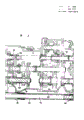
Fig. 1 a and 1b implement main transmission section vertical sectional side view of the present invention,
Fig. 2 is an intermediate drive part vertical sectional side view,
Fig. 3 is a back running part vertical sectional side view,
Fig. 4 is the front view of joining oil manifold,
Fig. 5 is the cutaway view of Fig. 4 along the A-A line,
Fig. 6 is the gear case front view,
Fig. 7 is the cutaway view of Fig. 6 along the B-B line,
Fig. 8 is the cutaway view of Fig. 6 along the C-C line,
Fig. 9 is the front view of gear case cover,
Figure 10 is the cutaway view of Fig. 9 along the D-D line,
Figure 11 is the cutaway view of Fig. 9 along the E-E line,
Figure 12 is the side-looking signal of trac..
Master of label 3 expression axle that travels, its front end is supported on the bent axle 1 with bearing 4, and bearing 7 is passed through in the rear end, is supported on the rear wall 6 of clutch bell 5.The main axle 3 that travels is connected with driving engine in steerable mode by the power-transfer clutch 8 that travels.
The front end of clutch bell 5 is opened wide, and forms a bead 5A, fixes with the crankcase of bolt not shown in the figures and driving engine.5 li placement flywheels of clutch bell and power-transfer clutch 8.Its rear wall 6 is dwindled gradually by a step shape part 5B, puts in backward in the open front of first transmission gearbox 9, with bolt not shown in the figures.
Hydraulic clutch is just being changeed in label 10 expressions, label 11 expression counter-rotating hydraulic clutches, and two power-transfer clutchs have same structure.
In this embodiment, the clutch body 15 of contrarotation can rotate jointly by spline 16 or similar device and the clutch spindle 12 that travels, and the clutch body 15 of Xiang Zhengzhuan ', by needle bearing 17, be installed in the first clutch end transmission shaft 12 ' on do relative rotation.
Power-transfer clutch main body 15 has an input gear and is installed in a transmission gear 19 engagement on main shaft 3 rear ends of travelling.Its positive and negative rotation has identical transmitting ratio.
Therefore, can know and see, just change hydraulic clutch 10 and counter-rotating hydraulic clutch 11, be installed in the forebody of first transmission gearbox 9, it is relative, relative in vertical direction in the present embodiment to cross the main axle 3 that travels.
Main speed-changing mechanism of label 25 expressions wherein in the present embodiment, has a constant-mesh type four stage change-over gear group.Secondary variable shaft 29 with the travel transmission shaft 27 and a band variable gear 28 of one group of different-diameter gear 26 is arranged in the main speed-changing mechanism 25.The transmission shaft 27 that travels is supported with main axle 3 almost coaxials that travel, an interlocking gear 30 is installed on its front end, this gear 30 and the gear parts 20B that is just changeing hydraulic clutch 10 directly mesh, and, be connected with counter-rotating hydraulic clutch 11 in steerable mode by an intermediate gear not shown in the figures.
This joins oil manifold 31 and an attaching parts 35 communicates, and attaching parts 35 has oil duct 35A, passes from the roof that flies transcapsidation 5.
Gear case of label 36 expressions wherein has last tube portion 37, passes through from manifold 31 backward.This gear case 36 has case lid 40, and case lid has a tubular support part 39, supports a clutch release sleeve 38.Gear case 36 and the case lid 40 common spaces that form therebetween.As mentioned above, the rear wall 6 of clutch bell 5 is inserted in the inside of transmission gearbox 9, joins oil manifold 31 and is fixed on the rear wall 6, and gear case 36 puts in the inside of manifold 31 on fore-and-aft direction.This arrangement can make the front and back length of trac. fuselage that sizable reducing arranged.
Label 41 expressions have the clutch end main shaft of a tubular structure, by needle bearing 42 and sealing member 43, are installed on the main axle 3 that travels.Clutch end main shaft 41 is supported on gear case 36 and the case lid 40 by bearing 44 and 45.And clutch end main shaft 41 front end is linked to each other with clutch case 47, thereby clutch end main shaft 41 directly links to each other by an arm 46 with driving engine.
Clutch end driving system of label 48 expression wherein has the first clutch end transmission shaft 12 ' and one second clutch end transmission shaft 50, in steerable mode by hydraulic clutch 49, with the first clutch end transmission shaft 12 ' link to each other.The first clutch end transmission shaft 12 ' from join oil manifold 31 and gear case 36, pass, by reduction gear 53, connect clutch end main shaft 41 in steerable mode, the gear 51 that is installed on the main shaft 41 is arranged in the reduction gear 53 and be installed in the first clutch end transmission shaft 12 ' on gear 52.
Clutch mechanism of label 54 expressions wherein has an operating fork 55 and cutoff clutch 38.Fork among Fig. 1 a 55 compressing clutch lever 56 that moves in the direction of the clock is drawn close to it, so power-transfer clutch 8 jump out of meshs.
In Fig. 2, creeping mechanism of label 57 expression wherein has wriggling input shaft 59, by plunging joint 58 and the wriggling output shaft 60 coaxial with wriggling input shaft 59, links to each other with secondary variable shaft 29.Two axles 59 and 60 interconnect by a mobile device 61.This creeping mechanism 57 is placed in the intermediate housing 62.
Clutch end main speed-changing mechanism of label 63 expressions has two speed in the present embodiment.Clutch end of label 64 expressions time speed-changing mechanism is placed in the intermediate housing 62, is used to provide two speed.
In Fig. 3, label 64 expressions are placed on a differential attachment in second transmission gearbox 65.Differential attachment 64 is connected with the transmission shaft 68 of secondary speed-changing mechanism 67 in steerable mode, and secondary speed-changing mechanism 67 is by plunging joint 66, is connected with the output shaft 60 of steerable mode and creeping mechanism 57.
Clutch end output shaft of label 69 expressions by a bearing arrangement 70, is supported in an end of second transmission gearbox 65, by a tween drive shaft 71, in steerable mode, is connected with clutch end second speed-changing mechanism 64.
Front-wheel drive propeller-shaft assembly set of label 72 expressions wherein has the gear 76 on 75 li on takeoff output axle box, by the gear 74 on gear on the transmission shaft 68 73 and the tween drive shaft 71, is connected with transmission shaft 68 in steerable mode.Gear 76 usefulness mobile devices 77 are connected with power take-off shaft 78, and power take-off shaft is connected with universal coupling 79 by a plunging joint 80.So assembly set 72 just controllably, be connected with the front-wheel differential attachment.
Universal coupling shell of label 81 expression, telescoping tube type flexible
Though the just commentaries on classics hydraulic clutch 10 shown in shown in Figure 1 can be with respect to 12 rotations of first dynamical axis, power- transfer clutch 10 and 11 position arrangements can be opposite with diagram in vertical direction.
Fig. 4 to 12 illustrates and joins oil manifold, gear case, the outward appearance of gear case cover and trac..
Referring to Fig. 4 and 5, join oil manifold 31 and form the mounting hole of arranging along its periphery 82, a depression 83 is arranged at an upper portion thereof, in order to hold seal ring 34, on a midway location on its vertical direction, an opening 84 is arranged, put the barrel portion 37 of gear case, in its underpart, an opening 85 is arranged, hold clutch end transmission shaft 12.
Referring to Fig. 6 to 8, gear case 36 is wherein arranged, barrel portion 37 is placed on the top of case 36, and is coaxial with hole 86, holds bearing 45.Gear case 36 also forms an opening 87 in the bottom, hold the first clutch end transmission shaft 12 ', and extra threaded hole 88 and mounting hole 89 are arranged, do assembly and disassembly and use.
Be gear case cover 40 among Fig. 9 to 11, form cutoff clutch supporting barrel portion 39 at an upper portion thereof, groove 90 is followed in the back, holds bearing 44, with the spring 91 of relative both sides, top, the pull back spring of fixedly separated sleeve 38.Gear case cover 40 also forms a groove 93, by a bearing 92, hold the first clutch end transmission shaft 12 ' front end, the tapped bore 94 that adds is arranged on its front surface, be used for assembly and disassembly, along periphery mounting hole 95 is arranged.Gear case 36 and gear case cover 40 form spaces between the two jointly, and can do the separation of fore-and-aft direction.
Figure 12 is shown with power transmission device of the present invention, and the trac. 96 of front-wheel 97 and trailing wheel 98 is arranged.But this trac. is a reverse mould, and operating seat 99 and bearing circle 100 can transpositions.
Claims (4)
1, power transmitting apparatus for tractor, comprise: a flywheel by the crank-driven of driving engine, travel axle 3 of master who links to each other by travel destage device 8 and driving engine in steerable mode is connected with flywheel, driving transmission agent main travel axle and differential attachment 69 ' between, clutch end main output shaft 41 around and by the main axle bearing that travels, and rotatably directly be connected with flywheel, a clutch end driving system is between clutch end main output shaft 41 and clutch end output shaft 69, rotating and reverse transfer device is included in the driving transmission agent, wherein, there is a clutch end transmission shaft operably to be connected the clutch end power-transfer clutch 49 of clutch end main shaft and the transmission system that friction speed is provided for clutch end output shaft 69 in the clutch end driving transmission agent with one, it is characterized in that: rotate and reverse converter apparatus and comprise just leaving and close apparatus 10 and reversing clutch device 11, clutch equipment is separately positioned on the opposite side of the main axle 3 that travels, one of them clutch equipment 10 or 11 can be contained in the relative rotation clutch end transmission shaft 12 ' on.
2, according to the power transmitting apparatus of claim 1, it is characterized in that: rotate and reverse clutch equipment and comprise hydraulic operated clutch equipment.
3, according to the power transmitting apparatus of claim 1 or 2, it is characterized in that: transmission system is contained in the downstream of clutch end power-transfer clutch and comprises a main speed-changing mechanism and time speed-changing mechanism.
4, according to any one power transmitting apparatus among the claim 1-3, it is characterized in that: the transmission shaft 27 that travels is arranged in the driving transmission agent, coaxial with the main axle that travels, rotate and reverse transfer device and be placed on therebetween, link to each other with steerable mode and main axle and the transmission shaft that travels of travelling.
Applications Claiming Priority (6)
| Application Number | Priority Date | Filing Date | Title |
|---|---|---|---|
| JP60-171592 | 1985-08-02 | ||
| JP171592/85 | 1985-08-02 | ||
| JP11946785U JPH0334338Y2 (en) | 1985-08-02 | 1985-08-02 | |
| JP60-119467 | 1985-08-02 | ||
| JP119467/85 | 1985-08-02 | ||
| JP60171592A JPS6231521A (en) | 1985-08-02 | 1985-08-02 | Power transmission device for tractor |
Publications (2)
| Publication Number | Publication Date |
|---|---|
| CN86103065A CN86103065A (en) | 1987-03-11 |
| CN86103065B true CN86103065B (en) | 1988-04-27 |
Family
ID=26457203
Family Applications (1)
| Application Number | Title | Priority Date | Filing Date |
|---|---|---|---|
| CN86103065A Expired CN86103065B (en) | 1985-08-02 | 1986-05-01 | Power transmitting apparatus for tractor |
Country Status (6)
| Country | Link |
|---|---|
| US (1) | US4685341A (en) |
| KR (1) | KR890004922B1 (en) |
| CN (1) | CN86103065B (en) |
| CA (1) | CA1260731A (en) |
| FR (1) | FR2585797B1 (en) |
| GB (1) | GB2178495B (en) |
Families Citing this family (5)
| Publication number | Priority date | Publication date | Assignee | Title |
|---|---|---|---|---|
| US5645363A (en) * | 1994-04-15 | 1997-07-08 | Dana Corporation | Bearing cap and pump mounting flange for power take-off unit |
| US6224289B1 (en) * | 1998-12-18 | 2001-05-01 | Kevin D. Redd | Power takeoff unit-driven unit adapter with sump lubrication |
| KR100988155B1 (en) * | 2008-01-23 | 2010-10-18 | 대동공업주식회사 | Transmission for tractor |
| CN102678839B (en) * | 2011-12-08 | 2015-05-13 | 河南科技大学 | Double-clutch transmission used in tractor |
| CN104728398A (en) * | 2015-03-25 | 2015-06-24 | 陕西法士特汽车传动集团有限责任公司 | Automobile full-power power takeoff |
Family Cites Families (20)
| Publication number | Priority date | Publication date | Assignee | Title |
|---|---|---|---|---|
| DE928571C (en) * | 1951-10-27 | 1955-06-02 | Zahnraederfabrik Augsburg Vorm | PTO drive on farm tractors |
| US2914966A (en) * | 1956-10-23 | 1959-12-01 | Case Co J I | Power transmission means for tractor |
| US3017003A (en) * | 1958-11-24 | 1962-01-16 | Borg Warner | Clutch |
| FR1333228A (en) * | 1962-06-15 | 1963-07-26 | Renault | Transmission block, especially for tractor |
| GB1294263A (en) * | 1971-03-30 | 1972-10-25 | Fichtel & Sachs Ag | Improvements in or relating to friction clutches |
| US3760918A (en) * | 1972-04-20 | 1973-09-25 | Deere & Co | Tractor pto and propulsion clutch assembly including lubrication means |
| DE2405023C2 (en) * | 1974-02-02 | 1982-07-08 | Klöckner-Humboldt-Deutz AG, 5000 Köln | Gear change transmissions in group design for motor vehicles, in particular for motor vehicles that can be used in agriculture and / or construction |
| US4116090A (en) * | 1974-03-02 | 1978-09-26 | Klockner-Humboldt-Deutz Aktiengesellschaft | Change gear transmission in group arrangement, especially for motor vehicles for use in agriculture and in the construction field |
| US3985044A (en) * | 1974-12-19 | 1976-10-12 | Ford Motor Company | Four speed manual transmission with concentric input and output shafts |
| GB1463920A (en) * | 1975-02-28 | 1977-02-09 | Kloeckner Humboldt Deutz Ag | Change-speed gear transmission of the multiple box type parti cularly for agricultural vehicles and/or self-propelled civil engineering machinery |
| JPS543732A (en) * | 1977-06-11 | 1979-01-12 | Kubota Ltd | Transmission structure for four-wheel drive tractor |
| JPS5467847A (en) * | 1977-11-10 | 1979-05-31 | Kubota Ltd | Running speed change gear for tractor |
| JPS54155356A (en) * | 1978-05-29 | 1979-12-07 | Kubota Ltd | Transmission for vehicle |
| IT1109610B (en) * | 1978-11-28 | 1985-12-23 | Fiat Trattori Spa | HIGH SPEED CHANGE OF SPEEDS FOR AGRICULTURAL TRACTORS AND SIMILAR VEHICLES |
| US4318305A (en) * | 1979-04-04 | 1982-03-09 | Deere & Company | Synchronized transmission |
| US4275607A (en) * | 1979-06-28 | 1981-06-30 | Twin Disc, Incorporated | Power transmission having power take-off shaft and fluid control means therefor |
| AU528214B2 (en) * | 1979-11-13 | 1983-04-21 | Kubota Ltd. | Vehicle transmission drive system |
| JPS5844225U (en) * | 1981-09-11 | 1983-03-24 | 株式会社クボタ | Double clutch type transmission PTO device |
| JPS58188223U (en) * | 1982-05-21 | 1983-12-14 | 株式会社クボタ | Tractor transmission |
| US4498349A (en) * | 1982-09-13 | 1985-02-12 | Iseki & Co., Ltd. | Front power take-off for tractors |
-
1986
- 1986-04-11 US US06/850,326 patent/US4685341A/en not_active Expired - Fee Related
- 1986-04-15 GB GB8609136A patent/GB2178495B/en not_active Expired
- 1986-05-01 CN CN86103065A patent/CN86103065B/en not_active Expired
- 1986-05-09 KR KR1019860003599A patent/KR890004922B1/en not_active IP Right Cessation
- 1986-05-14 FR FR868606929A patent/FR2585797B1/en not_active Expired - Lifetime
- 1986-06-03 CA CA000510722A patent/CA1260731A/en not_active Expired
Also Published As
| Publication number | Publication date |
|---|---|
| KR890004922B1 (en) | 1989-11-30 |
| GB2178495B (en) | 1989-12-28 |
| GB8609136D0 (en) | 1986-05-21 |
| GB2178495A (en) | 1987-02-11 |
| FR2585797A1 (en) | 1987-02-06 |
| CN86103065A (en) | 1987-03-11 |
| KR870001970A (en) | 1987-03-28 |
| US4685341A (en) | 1987-08-11 |
| CA1260731A (en) | 1989-09-26 |
| FR2585797B1 (en) | 1992-08-07 |
Similar Documents
| Publication | Publication Date | Title |
|---|---|---|
| EP0035324B1 (en) | Split axle drive mechanisms | |
| EP0030120B2 (en) | Transmission apparatus for four-wheel drive motor vehicle | |
| US4779698A (en) | Split axle drive mechanism for part-time four-wheel drive vehicle | |
| CA1281558C (en) | Vehicle drive-train transfer case | |
| US6412369B1 (en) | Four-wheel vehicle drive system | |
| JPH0650682Y2 (en) | Planetary gear type auxiliary transmission | |
| US4645029A (en) | Four-wheel vehicle drive system | |
| CN86103065B (en) | Power transmitting apparatus for tractor | |
| US5083635A (en) | Power transmission system for automotive vehicle | |
| JP2950567B2 (en) | Power transmission device | |
| GB2092968A (en) | Two/four-wheel drive system for a wheeled vehicle | |
| GB2173158A (en) | Transmission structure for agricultural tractor | |
| JPS6121830A (en) | Switching operator for 4-wheel drive device for car | |
| US4233857A (en) | Multiple speed transmission with auxiliary transfer drive | |
| EP0208478B1 (en) | Four-wheel vehicle drive system | |
| US4846016A (en) | Direct-coupling/differential changeover transfer apparatus | |
| JPS5938134A (en) | Four-wheel driving gear | |
| JPH0334341Y2 (en) | ||
| JP2609450B2 (en) | Travel transmission structure of agricultural tractor | |
| EP0480887B1 (en) | A rear axle for transmitting the driving torque to the rear wheels of a motor vehicle with disengageable four-wheel drive | |
| KR900005708B1 (en) | Power transmission for four wheel drive vehicle | |
| GB2199624A (en) | A change speed transmission | |
| GB2049073A (en) | Continuously-variable ratio transmission | |
| JPS6393609A (en) | Amphibious vehicle | |
| JPH0311062Y2 (en) |
Legal Events
| Date | Code | Title | Description |
|---|---|---|---|
| C10 | Entry into substantive examination | ||
| SE01 | Entry into force of request for substantive examination | ||
| C06 | Publication | ||
| PB01 | Publication | ||
| C13 | Decision | ||
| GR02 | Examined patent application | ||
| C14 | Grant of patent or utility model | ||
| GR01 | Patent grant | ||
| C19 | Lapse of patent right due to non-payment of the annual fee | ||
| CF01 | Termination of patent right due to non-payment of annual fee |