CN85109184A - High efficiency thermal unit - Google Patents
High efficiency thermal unit Download PDFInfo
- Publication number
- CN85109184A CN85109184A CN85109184A CN85109184A CN85109184A CN 85109184 A CN85109184 A CN 85109184A CN 85109184 A CN85109184 A CN 85109184A CN 85109184 A CN85109184 A CN 85109184A CN 85109184 A CN85109184 A CN 85109184A
- Authority
- CN
- China
- Prior art keywords
- heat
- water tank
- burner
- boiler
- nozzle
- Prior art date
- Legal status (The legal status is an assumption and is not a legal conclusion. Google has not performed a legal analysis and makes no representation as to the accuracy of the status listed.)
- Pending
Links
- XLYOFNOQVPJJNP-UHFFFAOYSA-N water Substances O XLYOFNOQVPJJNP-UHFFFAOYSA-N 0.000 claims abstract description 67
- 239000003546 flue gas Substances 0.000 claims abstract description 19
- 239000000446 fuel Substances 0.000 claims abstract description 14
- 239000000567 combustion gas Substances 0.000 claims abstract description 7
- 235000009781 Myrtillocactus geometrizans Nutrition 0.000 claims abstract description 4
- 240000009125 Myrtillocactus geometrizans Species 0.000 claims abstract description 4
- UGFAIRIUMAVXCW-UHFFFAOYSA-N Carbon monoxide Chemical compound [O+]#[C-] UGFAIRIUMAVXCW-UHFFFAOYSA-N 0.000 claims description 18
- 239000007789 gas Substances 0.000 claims description 10
- 239000007788 liquid Substances 0.000 claims description 10
- 239000002184 metal Substances 0.000 claims description 8
- 239000000295 fuel oil Substances 0.000 claims description 4
- 230000008676 import Effects 0.000 claims description 4
- 238000005452 bending Methods 0.000 claims description 3
- 230000005540 biological transmission Effects 0.000 claims description 3
- 238000009413 insulation Methods 0.000 claims description 3
- 239000012212 insulator Substances 0.000 claims description 3
- 239000002912 waste gas Substances 0.000 claims description 2
- 239000012530 fluid Substances 0.000 claims 2
- 230000001276 controlling effect Effects 0.000 claims 1
- 230000001105 regulatory effect Effects 0.000 claims 1
- 229910001220 stainless steel Inorganic materials 0.000 abstract description 5
- 239000010935 stainless steel Substances 0.000 abstract description 4
- 230000002093 peripheral effect Effects 0.000 abstract 1
- 238000002485 combustion reaction Methods 0.000 description 7
- 230000003321 amplification Effects 0.000 description 3
- 230000036541 health Effects 0.000 description 3
- 238000010438 heat treatment Methods 0.000 description 3
- 238000003199 nucleic acid amplification method Methods 0.000 description 3
- 239000002775 capsule Substances 0.000 description 2
- 230000006835 compression Effects 0.000 description 2
- 238000007906 compression Methods 0.000 description 2
- 238000007689 inspection Methods 0.000 description 2
- 238000012423 maintenance Methods 0.000 description 2
- 239000003921 oil Substances 0.000 description 2
- 230000035939 shock Effects 0.000 description 2
- 230000009471 action Effects 0.000 description 1
- 230000008901 benefit Effects 0.000 description 1
- 238000009835 boiling Methods 0.000 description 1
- 230000001413 cellular effect Effects 0.000 description 1
- 239000000919 ceramic Substances 0.000 description 1
- 230000008859 change Effects 0.000 description 1
- 238000009833 condensation Methods 0.000 description 1
- 230000005494 condensation Effects 0.000 description 1
- 238000010276 construction Methods 0.000 description 1
- 230000001351 cycling effect Effects 0.000 description 1
- 238000007599 discharging Methods 0.000 description 1
- 230000000694 effects Effects 0.000 description 1
- 239000000835 fiber Substances 0.000 description 1
- 239000003365 glass fiber Substances 0.000 description 1
- 230000005484 gravity Effects 0.000 description 1
- 239000011810 insulating material Substances 0.000 description 1
- 239000000463 material Substances 0.000 description 1
- 238000000034 method Methods 0.000 description 1
- 238000002156 mixing Methods 0.000 description 1
- 239000000203 mixture Substances 0.000 description 1
- 239000003973 paint Substances 0.000 description 1
- 230000008569 process Effects 0.000 description 1
- 238000011084 recovery Methods 0.000 description 1
- 230000000306 recurrent effect Effects 0.000 description 1
- 238000010992 reflux Methods 0.000 description 1
- 238000007634 remodeling Methods 0.000 description 1
- 230000003252 repetitive effect Effects 0.000 description 1
- 238000007789 sealing Methods 0.000 description 1
- 239000004071 soot Substances 0.000 description 1
- 239000007921 spray Substances 0.000 description 1
- 238000003756 stirring Methods 0.000 description 1
- 210000005239 tubule Anatomy 0.000 description 1
- 239000002699 waste material Substances 0.000 description 1
Images


Classifications
-
- F—MECHANICAL ENGINEERING; LIGHTING; HEATING; WEAPONS; BLASTING
- F24—HEATING; RANGES; VENTILATING
- F24H—FLUID HEATERS, e.g. WATER OR AIR HEATERS, HAVING HEAT-GENERATING MEANS, e.g. HEAT PUMPS, IN GENERAL
- F24H1/00—Water heaters, e.g. boilers, continuous-flow heaters or water-storage heaters
- F24H1/48—Water heaters for central heating incorporating heaters for domestic water
- F24H1/50—Water heaters for central heating incorporating heaters for domestic water incorporating domestic water tanks
-
- F—MECHANICAL ENGINEERING; LIGHTING; HEATING; WEAPONS; BLASTING
- F23—COMBUSTION APPARATUS; COMBUSTION PROCESSES
- F23C—METHODS OR APPARATUS FOR COMBUSTION USING FLUID FUEL OR SOLID FUEL SUSPENDED IN A CARRIER GAS OR AIR
- F23C5/00—Disposition of burners with respect to the combustion chamber or to one another; Mounting of burners in combustion apparatus
- F23C5/02—Structural details of mounting
-
- F—MECHANICAL ENGINEERING; LIGHTING; HEATING; WEAPONS; BLASTING
- F23—COMBUSTION APPARATUS; COMBUSTION PROCESSES
- F23C—METHODS OR APPARATUS FOR COMBUSTION USING FLUID FUEL OR SOLID FUEL SUSPENDED IN A CARRIER GAS OR AIR
- F23C7/00—Combustion apparatus characterised by arrangements for air supply
-
- F—MECHANICAL ENGINEERING; LIGHTING; HEATING; WEAPONS; BLASTING
- F23—COMBUSTION APPARATUS; COMBUSTION PROCESSES
- F23D—BURNERS
- F23D11/00—Burners using a direct spraying action of liquid droplets or vaporised liquid into the combustion space
- F23D11/24—Burners using a direct spraying action of liquid droplets or vaporised liquid into the combustion space by pressurisation of the fuel before a nozzle through which it is sprayed by a substantial pressure reduction into a space
- F23D11/26—Burners using a direct spraying action of liquid droplets or vaporised liquid into the combustion space by pressurisation of the fuel before a nozzle through which it is sprayed by a substantial pressure reduction into a space with provision for varying the rate at which the fuel is sprayed
- F23D11/28—Burners using a direct spraying action of liquid droplets or vaporised liquid into the combustion space by pressurisation of the fuel before a nozzle through which it is sprayed by a substantial pressure reduction into a space with provision for varying the rate at which the fuel is sprayed with flow-back of fuel at the burner, e.g. using by-pass
-
- F—MECHANICAL ENGINEERING; LIGHTING; HEATING; WEAPONS; BLASTING
- F23—COMBUSTION APPARATUS; COMBUSTION PROCESSES
- F23L—SUPPLYING AIR OR NON-COMBUSTIBLE LIQUIDS OR GASES TO COMBUSTION APPARATUS IN GENERAL ; VALVES OR DAMPERS SPECIALLY ADAPTED FOR CONTROLLING AIR SUPPLY OR DRAUGHT IN COMBUSTION APPARATUS; INDUCING DRAUGHT IN COMBUSTION APPARATUS; TOPS FOR CHIMNEYS OR VENTILATING SHAFTS; TERMINALS FOR FLUES
- F23L5/00—Blast-producing apparatus before the fire
- F23L5/02—Arrangements of fans or blowers
-
- F—MECHANICAL ENGINEERING; LIGHTING; HEATING; WEAPONS; BLASTING
- F24—HEATING; RANGES; VENTILATING
- F24H—FLUID HEATERS, e.g. WATER OR AIR HEATERS, HAVING HEAT-GENERATING MEANS, e.g. HEAT PUMPS, IN GENERAL
- F24H1/00—Water heaters, e.g. boilers, continuous-flow heaters or water-storage heaters
- F24H1/22—Water heaters other than continuous-flow or water-storage heaters, e.g. water heaters for central heating
- F24H1/24—Water heaters other than continuous-flow or water-storage heaters, e.g. water heaters for central heating with water mantle surrounding the combustion chamber or chambers
- F24H1/26—Water heaters other than continuous-flow or water-storage heaters, e.g. water heaters for central heating with water mantle surrounding the combustion chamber or chambers the water mantle forming an integral body
- F24H1/28—Water heaters other than continuous-flow or water-storage heaters, e.g. water heaters for central heating with water mantle surrounding the combustion chamber or chambers the water mantle forming an integral body including one or more furnace or fire tubes
- F24H1/287—Water heaters other than continuous-flow or water-storage heaters, e.g. water heaters for central heating with water mantle surrounding the combustion chamber or chambers the water mantle forming an integral body including one or more furnace or fire tubes with the fire tubes arranged in line with the combustion chamber
-
- Y—GENERAL TAGGING OF NEW TECHNOLOGICAL DEVELOPMENTS; GENERAL TAGGING OF CROSS-SECTIONAL TECHNOLOGIES SPANNING OVER SEVERAL SECTIONS OF THE IPC; TECHNICAL SUBJECTS COVERED BY FORMER USPC CROSS-REFERENCE ART COLLECTIONS [XRACs] AND DIGESTS
- Y02—TECHNOLOGIES OR APPLICATIONS FOR MITIGATION OR ADAPTATION AGAINST CLIMATE CHANGE
- Y02E—REDUCTION OF GREENHOUSE GAS [GHG] EMISSIONS, RELATED TO ENERGY GENERATION, TRANSMISSION OR DISTRIBUTION
- Y02E20/00—Combustion technologies with mitigation potential
- Y02E20/34—Indirect CO2mitigation, i.e. by acting on non CO2directly related matters of the process, e.g. pre-heating or heat recovery
Abstract
A heat engine comprises a clean blue flame burner 1 and a stainless steel boiler (2) with several water tanks. The burner has a nozzle casing 10 welded to the boiler 2 and a movable rear part mounted on the nozzle casing 10. The rear portion of the burner includes a labyrinth passage for preheating the combustion gases and a thermally insulated conduit for feeding fuel to the nozzle. The boiler 2 has a furnace 8 delimited by two water tanks 5, 12, namely a main peripheral tank and a tail tank located downstream of the furnace 8 and delimiting a gap with the main tank, through which the flue gases are conveyed, giving off heat to the water in the tanks.
Description
The present invention relates to a kind of high-efficiency thermal group that includes an evaporimeter and a clean blue flame burner.
The operational efficiency of heat group depends on the efficient of thermal characteristics and boiler and to a great extent at the exchange rate between heated water and the flue gas in the boiler.
Know that in the burner of combustion of liquid fuel, for example in the oil burner, fuel must be supplied and could eject well in suitable nozzle under pressure.May often this thing happens, be that burner is after lighting a fire periodically repeatedly and stopping working operation, after being disconnected, ignitor electrode still have fuel in a small amount to be transfused to burner, these fuel quantities are not except burning is wasted in fact because of them, also can accumulate in the inside of burner, crossed and also can cause obstruction a period of time of after and cause that soot deposits is deposited on the inwall of the combustion chamber of burner that will cause to have unburned material in flue gas, equipment so just needs repairing.
In addition, when burner is when periodically starting, the liquid fuel that also may be supplied to it in the passage that is supplied to nozzle in stove by overheated.Like this, in continuous operating process,, the heating of the inwall of boiler inner burner raises owing to causing strong local temperature.The result that fuel is heated can cause therefore the stability of flame and continuity being degenerated, and causing imperfect combustion and efficient to reduce from the unexpected increase of the fuel oil stream of nozzle ejection.
The purpose of this invention is to provide a kind of new high efficiency heat group, it can limit or significantly reduce above-mentioned shortcoming.
Another purpose of the present invention provides a kind of heat group with simple and Rational structure, make its mounting or dismounting of component part all very convenient, maintenance can very promptly be carried out and overhaul to feasible inspection easily, even the innermost component inspection maintenance of heat group also is like this.
The present invention why can reach above-mentioned purpose and other will be progressively in narrating afterwards tangible purpose, be because it has a high efficiency heat group.It includes a boiler and a clean blue flame burner, wherein said boiler comprises that at least one contains the metal head liquid case that is heated liquid and defines a burner hearth, described burner stretches into this burner hearth, tail end liquid case with at least one metal, this liquid case is positioned at the downstream of the burner hearth of described burner at least in part, this tail end or each tail end water tank define a gap or slit with the limit wall of burner hearth and controllably limit and allow the flue gas of heat by the there, provide a throttling passage to the hot flue gas in the burner hearth, thereby obtained the flue gas of heat and high efficiency heat transmission between the liquid in the liquid case.
Other characteristics of the present invention and advantage will be from following to being able to being described in detail of most preferred embodiment obviously, below connection with figures provide most preferred embodiment, but the present invention never is limited to this several optimum examples that exemplifies for explanation.
Fig. 1 one is used for the front view of signal vertical section of first embodiment of the heat group of vertical layout operation.
Fig. 2 is the top view of heat group shown in Figure 1.
Fig. 3 is the schematic sectional view of the amplification of burner in the heat group shown in Fig. 1 and 2 and corresponding input system.
Fig. 4 is the cross sectional view of the amplification that changes to some extent of the structure of a control device.
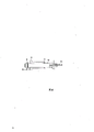
Fig. 5 is the longitudinal cross-section view that is used for second embodiment of horizontal layout operation heat group.
In these accompanying drawings, identical or similar part will be indicated with same numbering among the different embodiment.
Heat group as shown in Figures 1 to 3, oil or air burner indicate with 1,2 signs, one boiler, and burner 1 is installed in above it.
Boiler 2 be closed in once paint or the shell of glazy metallic plate in, its outside is with a kind of thick-layer institute thermal insulation of suitable heat insulator system, for example the protection case made from ceramic fibre or glass fibre 4.Boiler 2 comprises the main head water tank or the water tank 5 of an inner annular, and it is used for hot water being supplied to the heating system (not shown) by output channel 6 and then refluxing by entering pipeline 7.This head water tank 5 has the wall of metal, and stainless steel wall for example defines a boundary line of bearing seat 9 that is used as the nozzle 10 of the boundary line of inner chamber 8 of burner hearth and burner 1 simultaneously, and this bears the end that seat 9 is positioned at chamber 8, preferably and the chamber be coaxial line.Around and against water tank 5, an outer ring metal water tank 12 is arranged, stainless steel water tank for example, by efferent duct 13, recurrent canal 14 is connected with the supply system (not shown) of health water with circulation pipe 15.
At the other end of furnace chamber 8, there is the preheating water tank 16 in a downstream there, and it has the wall of metal, and stainless steel wall for example, preheating water tank 16 and the limit wall of burner hearth 8 define the boundary in narrow continuous circular shape gap 17 jointly.Water tank 16 (be it facing to an end of nozzle 10) and bottom is supported by one or several duct member 18 on the burner hearth core (or penetralia wall of water tank 5) at the top, this duct member also is used for setting up the connection of direct water between water tank 5 and 16, thereby prevents to form the steam capsule for 16 li at water tank.
As shown in Figure 1, because health water outlet pipe 13 is contained in water tank 4 next segment distance of top, so water tank 4 can be full of fully by water.Be to make water tank 4 also can be used as expansion tank to use like this.Like this, heat group of the present invention just need be in general hot system the required gas charging system that separates usually.The flue-gas temperature in the exit of annular gap 17 is lower usually, (about 70-100 ℃) they enter water collector 23, gatherer is communicated with the chimney (not shown) by horizontal passage 24, has a bend pipe 25 to be used for condensate water is drained into sewerage by pipeline 26 on the end of water collector 23.Therefore water collector 23 also plays a part end cap, also can load onto the explosion-proof check door 27 with spring on it.
Boiler 2 also can have instrument board 28(Fig. 2), according to the condition in space and use near etc. principle, this instrument board can place arbitrary limit on illustrated boiler three limits, (when using facing to wall one side).
Certainly, boiler 2 also has instrument and auxiliary equipment, for example is used for observing from the outside the window 29 of the flame of 8 li in burner hearth, the supervisory keyboard that hot measuring head 30, one usefulness 31 are numbered etc.Window 29 can be hinged on one in the outside of access tube 32, so that can be used as a kind of lid that can open automatically in order to discharge the 8 any compression shock that takes place, for example compression shocks when burner 1 begins to light a fire in the burner hearth.As 29 of operculums face be the face of together horizontal tilt, can automatically close pipe 32 at the effect lower cover of gravity so.
In order to increase exerting oneself of heat group, in general must increase the power of burner.But in certain limit (limit), this increase of exerting oneself need not to change other size as long as the length that increases burner hearth 5 simply just can reach.
Burner 1 preferably is welded on its nozzle pipe 10 on the seat 9 of boiler, it comprises that one has the ring-type bell shape ducted body 40 of flange 41 simultaneously, flange 41 can be fixed on the outer end of nozzle pipe 10 with bolt 42, lining 43 have the standard inner chamber by seat on the flange 41 of ducted body 40, one cap or cover 44 flange 45 is arranged, lid 44, as described below, supporting a underslung termination nozzle 46, removably be fixed on the flange 41 of body 40 with discharging rotation pin 41a fast.More specifically say, the inner chamber of this bell jar body 40 includes narrow cylindrical bottom part (section) 47 at flange 41 places that delimit 43 boundary lines of lining, cylindrical end portion (section) 49 from the 48 and amplifications of middle truncated cone part (section) that expand outwardly away of part (section) 47.The cap 45 on flanged limit delimited a boundary line that comes down to columniform inner chamber 50, this inner chamber 50 is preferably coaxial with the inner chamber of bell jar body 40, the fin 51 that also has the radiation-like that many longitudinal directions stretch, for example it be circumference equally distributed and from roof 52 stretch away until it sidewall length 2/3.On the outer wall of ducted body 40 barrel portions (section), also have fin 53 longitudinally.The combustion gas physical efficiency is by the import on sidewall input inner chamber 50, this import be positioned at flange end 45 and by a passage 57(flexibility) be communicated with blower fan or fan case 56.Because the shape of inner chamber 50 and the structure of bell jar body 40, supplied the flange 41 that the burning gases that come skim over tapering part (section) and bell jar body earlier by fan 56, the part of heat normally when these parts are used, simultaneously because fin 51 and 53, burning gases are walked be one along passage bending or mazy just along moving towards wall 52 at bell jar body 40 and the annular gap covered between 44, being reflected again there enters bell jar body 40.
By building 44 wall 52, cover 58 is supporting to be stretched over simultaneously bell jar body 40 inside with being draped formula.Pipe 60 is contained in 58 li in cover slidably and hermetically by one or several sealing 59, and the inside of stretching ducted body 40 simultaneously arrives the end of cover 43 always.Free end or top pipeline 60 at it have nozzle 46.
This pipeline 60 has two vertically mouthful, i.e. an axial port 61 and a lateral port 62, and the latter comes down to be parallel to that axial port stretches, and two mouths 61 and 62 all are communicated with the inlet part of nozzle 46.One tubule 63 by heat insulator system inserts in the mouth 61.Pipeline 60 is being supported a dish 64, and it is positioned at cylindrical part (section) lining of bell jar body 40 and passes through around disc circumference a throttling action to be provided, to allow the burning gases (it is an annular distribution) that enter near bullet section (section) 48.Before making gas just be subjected to turbulent mixture between dish 64 downstream cover 43 and frusto-conical portion 48 like this its speed has been increased, just by overlap 43 and nozzle 46 enter nozzle pipe 10 before combustion gas by speedup.
Overlap the position of 58 li conduit 60, correspondingly nozzle 46 is to adjust with the collar nut 65 and the locking nut 67 of the outer knurled that is screwed into the threaded portion that stretches out at cover 58 rear portions with respect to the position of the standard inner chamber of cover 43.As a version, also can with as shown in Figure 4 be contained on the retainer ring 70 on the conduit 60 and the measuring screw 69 that withstands on cover 58 carries out this adjustment.
Near the part of cover 43, the there provides one or several igniter plug or electrode 71(Fig. 2 and 3 on the nozzle sleeve pipe).
Pipe 63 and passage 62 are communicated with passage 73,72 accordingly by being numbered 74 two-way control device and two magnetic valves 75 and 76, with valve 76 and pipe 63 passages that are communicated with 72, the output of the fuel feed pump 78 that drives from motor 79 stretches out, and passage 73 has then been formed the route of fuel flow returns to pump 78. Magnetic valve 75 and 76 is controlled by total control device (not shown) in use.Magnetic valve 75 can be controlled to allow some fuel to get back to pump 78 by control device 90.This just means that what the time be supplied to nozzle 46 in igniting is the fuel oil that pressure reduces, thus guaranteed igniting steadily avoid causing any undesirable strong blast by chimney.
This arrangement has been arranged, after finishing, each combustion process just prevented the pressure fuel oil to flow into nozzle pipe 10(combustion chamber), this trapped fuel is still 63 li of pipes, when valve 76 cuts out, to enter return duct 73 rather than arrive nozzle 46 along mouth 62 with by valve 75, therefore, nozzle and combustion chamber can both keep clean.
Motor 76 also arranges to come drive fan or blower fan 56, and the output 80 of blower fan is communicated with pipeline 57 by silencer-filter 81.Suction inlet 83 at blower fan also is equipped with silencer-filter 82.
Very advantageously, blower fan 56 has the choke valve that a by-pass line 84(who is controlled by valve 85 is for example controlled by control device).When no-voltage was added to electrode 71, promptly burner was when extinguishing, and this valve 85 just cuts out to prevent that cold air from entering boiler.When burner operation, this valve 85 is opened bypass channel 84, and like this, the receptible a certain amount of combustion gas of heat group is supplied to burner, and the air of any excess is just by blower fan repetitive cycling (arrow A).Such arrangement has been arranged, in the burner hearth of boiler, obtained more stable flame and do not have energy to be wasted.
The running of above-mentioned heat group should be very clearly.Make by heat-insulating material because manage 63, thus fuel before arriving nozzle, can not be preheated, even burn cycle repeats again and again, the part orthicon road 60 of burner, cover 58 and cover 44 and all generate heat, fuel can not be preheated yet.This is to observing the special regulations carried out in many countries and being a kind of important factor for all even stable flame both is provided in 8 li in burner hearth.
Illustrate as top, the burning gases that are supplied to chamber 50 by blower fan are the passage that is compelled to by bending before entering combustion chamber 10, do mainly containing two reasons like this, exactly before participating in burning to abundant preheating of the burning gases of coming in and mixing fully.
When voltage cut off, motor stopped, and valve resets, and this moment, burner was flame-out.
Embodiment shown in Figure 5 except it cellular construction and horizontal to do out of trade be with above-mentioned unit affinity.This pattern is suitable for the heat group that power is higher than 100,000 kilocalories/hour.Because the high-power heat group of this class does not need the health water supply system, so do not need to install outer water tank.Water tank 5 has and can therefore become hot component the part transportation by narrow passage before assembling with the mutual fastening flange assembly of bolt.
The most preferred embodiment of above-mentioned two kinds of heat groups can have many variations and remodeling, the patent right range of the present invention that they all should propose in the application's claim book.
For example, boiler water tank 4 and 5 the most handy stainless steels are made, and boiler also can move under lower temperature, and for example 40 ℃ to 60 ℃, this section temperature is a kind of suitable temperature to being connected on the solar panel or being used for indoor heating application facet. Should be noted that, owing to obtain high efficiency heat exchange by annular gap 17, the temperature that is drained into the waste gas of water collector 23 or flue gas is lower, greatly between 70 ℃-100 ℃, like this, the condensation of the steam in the flue gas of discharge has taken place to be suspended in 23 li of water collectors, from and increased release and the recovery of some heats.
In addition, should than common bundled tube boiler big inner chamber be arranged with one or more water tanks 4,5,16 boiler structure, thereby to a certain degree reduce the problem of bringing because of fouling on the inwall of boiler.
Claims (14)
1, one high efficiency heat group has a boiler (2) and a clean blue flame burner (1), wherein said boiler (2) comprises the head water tank (5) of a metal that contains heated fluid at least and defines the boundary line that described burner (1) stretches the burner hearth (8) of entering, be positioned at the described burner hearth (8) in burner (1) downstream at least in part with at least one metal tail water tank (16), should or the sidewall of each afterbody water tank (16) and burner hearth marked gap or slit (17) the boundary line controllably to limit and to carry hot flue gas by it, therefore provide one to be used for the throttling passage of hot flue gas and to obtain flue gas from heat to water tank (5 in burner hearth (8) lining, 16) the high efficiency transmission of the heat of the liquid of lining.
2, heat group as claimed in claim 1, it is characterized in that should or at least a portion of each described afterbody water tank (16) and the gap (17) that described head water tank (5) has certain distance so marked an annular circumferential between them.
3, heat group as claimed in claim 1 or 2 is characterized in that this or each described afterbody water tank (16) are fluid connections with this or each described head water tank (5).
4, as any described heat group of claim 1 to 3, it is characterized in that innermost afterbody water tank (16) has a protection case (20) as flame or gas baffle.
5, as the described heat group of above-mentioned any claim, it is characterized in that it comprises that one is suspended in the collection space (23) of condensed water, waste gas or flue gas in the flue gas in order to collection, and the downstream that this described chamber (23) is arranged at described slit (17) is communicated with chimney (24), is equipped with condensate draining bend pipe (25) simultaneously.
6,, it is characterized in that it further includes at least in part around at least one outer water tank (12) of this or each described head water tank (5) and carries out heat exchange each other to heat liquid wherein as the described heat group of above-mentioned any claim.
7, as claim 5 or 6 described heat groups, it is characterized in that it comprises the outer cover (4) of a heat insulator.
8, as the described heat group of above-mentioned any claim, it is characterized in that this burner (1) comprises that a nozzle set (10) is fixed on boiler (2) and goes up and be stretched in the boiler furnace (8), with one movably combination be fixed on described nozzle set (10) and go up and comprise that a hollow (40) that flange arranged is fixed to from an end of the nozzle set of boiler (2) protrusion with its flange one (41), one standard cover 43 is put at the flange (41) of described hollow (40) to be located, therefore the inner chamber of described hollow (40) directly communicates with described nozzle set (10), it covers one block (44) described hollow (40) and defines one therewith an import (54) that is used for burning gases is arranged with the circumferential cavity (50) of the intracavity inter-connection of described hollow (40) with in its end of the flange end that is close to hollow (40), therefore the combustion gas of coming in by described import (54) is carried along the passage of bending by described circumferential cavity (50) before entering described hollow (40), advance described hollow (40) and described standard cover (43) with a cover (60) and a stretching, extension that is contained on the described cap (44), one nozzle (46) be contained on the described cover (60) and a thermal insulation or stretched along described cover (60) by heat-insulating conduit (63) fuel supplied with described nozzle (46).
9, heat group as claimed in claim 8, it is characterized in that forming at least in part on the inwall of described cap (44) be arranged to guiding and discharge heat give the burning gases that flow through described circumferential cavity (50) vertically and/or fin radially 51.
10, heat group as claimed in claim 8 or 9 is characterized in that described flanged (FLGD) hollow (40) is provided or provides at least in part the longitudinal fin (53) of the outside designed of matching with fin (51) on described cap 44.
11, as each described heat group of claim 8 to 10, it is characterized in that described cover has or comprise that one is used for the return flow line (62) at the fuel oil of described nozzle (46) lining.
12,, it is characterized in that it further includes to be used for controlling described thermal insulation or by the two-way valve of heat-insulating passage (63) (75,76) and described return flow line (62) as claim 8 and 11 described heat groups.
13, as claim 8 or 11 or 12 described heat groups, it is characterized in that described cover (60) is useful on the adjusting device (65) of regulating its relative position on described cap (44), therefore described nozzle (46) can be adjusted from described standard cover (43) and move into or shift out.
14, organize as each described heat of claim 8 to 13, it is characterized in that it further comprises is used to supply the blower fan (56) that combustion gas is given burner, the valve (85) that described blower fan (56) has the bypass (84) of an inside and is used to cut out described bypass (84) and stays open when moving when described blower fan.
Applications Claiming Priority (2)
| Application Number | Priority Date | Filing Date | Title |
|---|---|---|---|
| IT84978A/84 | 1984-12-21 | ||
| IT84978/84A IT1181493B (en) | 1984-12-21 | 1984-12-21 | HIGH PERFORMANCE THERMAL GROUP CONSISTING OF A BOILER AND TRANSPARENT BLUE FLAME BURNER |
Publications (1)
| Publication Number | Publication Date |
|---|---|
| CN85109184A true CN85109184A (en) | 1986-06-10 |
Family
ID=11326762
Family Applications (1)
| Application Number | Title | Priority Date | Filing Date |
|---|---|---|---|
| CN85109184A Pending CN85109184A (en) | 1984-12-21 | 1985-12-20 | High efficiency thermal unit |
Country Status (10)
| Country | Link |
|---|---|
| US (1) | US4633820A (en) |
| EP (1) | EP0185340B1 (en) |
| JP (1) | JPS61153439A (en) |
| CN (1) | CN85109184A (en) |
| AT (1) | ATE57760T1 (en) |
| CA (1) | CA1251698A (en) |
| DE (1) | DE3580253D1 (en) |
| ES (1) | ES8700416A1 (en) |
| GR (1) | GR853109B (en) |
| IT (1) | IT1181493B (en) |
Families Citing this family (8)
| Publication number | Priority date | Publication date | Assignee | Title |
|---|---|---|---|---|
| AT389164B (en) * | 1986-09-11 | 1989-10-25 | Olymp Werk A Schwarz Ges M B H | BOILER |
| US4825814A (en) * | 1988-03-10 | 1989-05-02 | Stirling Thermal Motors, Inc. | Combination gas combuster and heat pipe evaporator device |
| DE9301606U1 (en) * | 1993-02-05 | 1994-06-01 | Viessmann Werke Kg | Heat generator for water heating and heating operation |
| DE29814868U1 (en) * | 1998-08-19 | 1999-12-30 | Hoval Interliz Ag Vaduz | boiler |
| DE10110637A1 (en) * | 2001-03-06 | 2002-10-02 | Winkelmann Gmbh Stahl Behaelte | Water heater for domestic water heating |
| CA2503056A1 (en) * | 2005-04-07 | 2006-10-07 | Louis Cloutier | Boiler with anteroom and spiral exchanger |
| US7500454B2 (en) * | 2007-01-22 | 2009-03-10 | Charles Junior Frasure | High efficiency water heater |
| CN106403268A (en) * | 2016-05-18 | 2017-02-15 | 高常宝 | Alcohol-based oil water heater |
Family Cites Families (18)
| Publication number | Priority date | Publication date | Assignee | Title |
|---|---|---|---|---|
| US1681305A (en) * | 1928-08-21 | Water heater | ||
| US1988263A (en) * | 1933-01-30 | 1935-01-15 | Weil Mclain Co Inc | Boiler and water heater system |
| US2354507A (en) * | 1940-09-09 | 1944-07-25 | Doherty Arthur | Combination furnace and water heater |
| US2552044A (en) * | 1945-09-24 | 1951-05-08 | Comb Eng Superheater Inc | Directly fired waste-heat boiler |
| FR947042A (en) * | 1947-05-14 | 1949-06-21 | Automatic accelerated pulsation and burner boiler | |
| NL135170C (en) * | 1962-10-31 | 1900-01-01 | ||
| USB473366I5 (en) * | 1965-07-20 | |||
| LU59032A1 (en) * | 1969-07-04 | 1969-11-15 | ||
| US4134719A (en) * | 1976-09-27 | 1979-01-16 | Velie Wallace W | Multi-flame fuel burner for liquid and gaseous fuels |
| US4242569A (en) * | 1978-04-24 | 1980-12-30 | Kayser William M | Multiple tank electric water heater |
| FI802132A (en) * | 1979-07-20 | 1981-01-21 | Zampieri P | VAERMEPANNA MED FYRBOX UNDER TRYCK |
| CH638883A5 (en) * | 1979-08-27 | 1983-10-14 | Eugen Josef Siegrist | BOILER. |
| NL7907833A (en) * | 1979-10-25 | 1981-04-28 | Tricentrol Benelux | HOT WATER BOILER, FOR EXAMPLE, A CENTRAL HEATING BOILER. |
| DE2943289C2 (en) * | 1979-10-26 | 1983-08-18 | Peter 7300 Esslingen Witkowski | Burners for liquid and / or gaseous fuels, in particular for industrial furnaces |
| IT1159293B (en) * | 1982-04-23 | 1987-02-25 | Giavelli Mec Spa | BURNER WITH COMBUSTION AIR PREHEATING, ESPECIALLY FOR CERAMIC COOKING OVENS |
| FR2525745B1 (en) * | 1982-04-27 | 1987-09-25 | Lecomte Robert | IMPROVEMENTS ON HEAT GENERATORS FORMING CONDENSING BOILERS |
| FR2533676A1 (en) * | 1982-09-24 | 1984-03-30 | Filerie Electr Caladoise | Method for electrical central heating with the production of hot water for sanitary use incorporated, and boiler for the implementation thereof. |
| DE3320842A1 (en) * | 1983-06-09 | 1984-12-13 | Georg 4520 Melle Stönner | Heating boiler |
-
1984
- 1984-12-21 IT IT84978/84A patent/IT1181493B/en active
-
1985
- 1985-12-09 US US06/806,582 patent/US4633820A/en not_active Expired - Fee Related
- 1985-12-16 EP EP85116003A patent/EP0185340B1/en not_active Expired - Lifetime
- 1985-12-16 AT AT85116003T patent/ATE57760T1/en not_active IP Right Cessation
- 1985-12-16 CA CA000497713A patent/CA1251698A/en not_active Expired
- 1985-12-16 DE DE8585116003T patent/DE3580253D1/en not_active Expired - Lifetime
- 1985-12-17 ES ES550026A patent/ES8700416A1/en not_active Expired
- 1985-12-20 GR GR853109A patent/GR853109B/el unknown
- 1985-12-20 JP JP60285881A patent/JPS61153439A/en active Pending
- 1985-12-20 CN CN85109184A patent/CN85109184A/en active Pending
Also Published As
| Publication number | Publication date |
|---|---|
| DE3580253D1 (en) | 1990-11-29 |
| JPS61153439A (en) | 1986-07-12 |
| ES8700416A1 (en) | 1986-10-16 |
| ATE57760T1 (en) | 1990-11-15 |
| ES550026A0 (en) | 1986-10-16 |
| CA1251698A (en) | 1989-03-28 |
| IT8484978A0 (en) | 1984-12-21 |
| EP0185340A3 (en) | 1986-08-06 |
| EP0185340A2 (en) | 1986-06-25 |
| GR853109B (en) | 1986-04-22 |
| EP0185340B1 (en) | 1990-10-24 |
| US4633820A (en) | 1987-01-06 |
| IT1181493B (en) | 1987-09-30 |
Similar Documents
| Publication | Publication Date | Title |
|---|---|---|
| US4651714A (en) | High efficiency water heater | |
| US5816199A (en) | High efficiency water heater | |
| CN85109184A (en) | High efficiency thermal unit | |
| CN102235814B (en) | Direct-combustion hot blast heater | |
| US4020822A (en) | Multi-fuel forced air furnace | |
| EP0194237B1 (en) | Free flame burner with turbulent atomisation by means of gaseous combustion products | |
| CA1091108A (en) | Boiler | |
| CN205878143U (en) | It is automatic control methyl alcohol environmental protection boiler technique device to reform transform coal burning boiler | |
| DE3478871D1 (en) | Heating installation | |
| CN87216988U (en) | Two-circuit indirectly-heating hot-blast stove using metal body and burnt coal | |
| CN201217675Y (en) | Thermal treatment control device | |
| CN1178248A (en) | Heat treating apparatus for ensembled large size spherical tank | |
| CN105757975A (en) | Smokeless warm bath boiler | |
| CN100529540C (en) | Safety boiler applying coal gas to industry boiler | |
| CN201293314Y (en) | Low NOx slag tapping double rotational flow coal powder burner | |
| CN201163047Y (en) | Energy-saving environment friendly large frying stove | |
| US3456606A (en) | Combustion apparatus | |
| CN2371334Y (en) | Coil heating stove | |
| CN2267421Y (en) | Ambient pressure hot water and steam generating heater using oil as fuel | |
| CN210511670U (en) | Novel self-cooling injection type combustor | |
| RU10854U1 (en) | WATER HEATING BOILER | |
| EP0604671B1 (en) | A device for the exploitation of the heat of flue or exhaust gases | |
| CN2182962Y (en) | Indirect air heater burning oil or gas | |
| CN2160854Y (en) | Vertical hot-blast stove using heavy residual stocks | |
| CN2152975Y (en) | Helix tube three-reverse running type heat conducting oil boiler |
Legal Events
| Date | Code | Title | Description |
|---|---|---|---|
| C06 | Publication | ||
| PB01 | Publication | ||
| C10 | Entry into substantive examination | ||
| SE01 | Entry into force of request for substantive examination | ||
| WD01 | Invention patent application deemed withdrawn after publication |