CN2717655Y - Injection moulding machine die rotary mechanism - Google Patents
Injection moulding machine die rotary mechanism Download PDFInfo
- Publication number
- CN2717655Y CN2717655Y CN 200420071573 CN200420071573U CN2717655Y CN 2717655 Y CN2717655 Y CN 2717655Y CN 200420071573 CN200420071573 CN 200420071573 CN 200420071573 U CN200420071573 U CN 200420071573U CN 2717655 Y CN2717655 Y CN 2717655Y
- Authority
- CN
- China
- Prior art keywords
- shaft
- rotating mechanism
- injection machine
- machine mould
- rotating
- Prior art date
- Legal status (The legal status is an assumption and is not a legal conclusion. Google has not performed a legal analysis and makes no representation as to the accuracy of the status listed.)
- Expired - Fee Related
Links
Images


Landscapes
- Injection Moulding Of Plastics Or The Like (AREA)
- Moulds For Moulding Plastics Or The Like (AREA)
Abstract
The utility model relates to an injection moulding machine die rotary mechanism, comprising a rotary plate for fitting mould, a big gear fixed on the rotary plate, a rotary mechanism on the double-plate driving the big gear in motion, a hollow rotary axle of the big gear on the double-plate, an oil matching on the hollow rotary axle, a water matching on the hollow rotary axle, and a rotary mandrel and a rotary device driving the rotary mandrel in motion in the hollow axle connected with the oil casing. The utility model provides two mould rotation functions; the rotary plate rotates in 180 degrees used for mould and the rotary mandrel rotates in 180 degrees used for mould core. The advantages include rapid action responding, steady operation, and compact conformation.
Description
Technical field
The utility model relates to a kind of injection machine mould rotating mechanism.
Technical background
The traditional injection moulding injection machine generally only has the function of rotating disk or rotation mandrel the two one of them; In addition, in the driving control of rotating disk, generally adopt at present hydraulic driving mode: oil motor or oil cylinder, like this, at whole course of action slowly and not steady.
The utility model content
The purpose of this utility model provides and a kind of rotating disk and rotation mandrel is combined, and course of action reaches the injection machine mould rotating mechanism of stable working soon.
In order to achieve the above object, the utility model is to realize like this, the rotating disk that comprises installation mold, it is characterized in that: also comprise the gear wheel that is fixed on the rotating disk, be located at the rotating mechanism that the drive gear wheel on two plates rotates, be located at the hollow rotating shaft of the gear wheel on two plates, the oil content that is located on the hollow rotating shaft is supporting, the moisture that is located on the hollow rotating shaft is supporting, is located in the hollow shaft and is connected with the supporting oil-feed cover of oil content and the tumbler of rotating rotation mandrel and the rotation of driven rotary mandrel.
The utility model further is improved to, at the flexible feet that is provided with on the rotating disk more than three.Flexible feet comprises disk spring and shoes.The positioner that also comprises rotating disk, this device comprise locating shaft and drive the oil cylinder of locating shaft motion, have the hole that adapts with locating shaft accordingly on rotating disk.The tumbler of rotation mandrel comprises that motor reaches the shaft gear of offering spline by its drive, has free-sliding spline accordingly on the rotation mandrel.Also comprise the secondary support means that is located at the rotating disk on two plates, this device comprises eccentric shaft and is located at roller on the eccentric shaft.Also comprise the axial direction positioning device that is located at the rotating disk on two plates, this device is spacing briquetting.The rotating mechanism that described drive gear wheel rotates comprises AC servomotor and gearbox thereof.
The utility model further is improved to again, and rotating disk is a spoke structure.The positioner that also comprises shaft gear, this device comprise locating shaft and drive the oil cylinder of locating shaft motion, have the hole that adapts with locating shaft accordingly on shaft gear.
The advantage of the utility model and prior art is that it is selective fully to have two kinds of mould spinfunctions.Rotating disk is used for mould and does 180 ° of rotations, and the rotation mandrel is used for core rod and does 180 ° of rotations; The inertia of rotating disk+mould is big, uses the AC driven by servomotor, can realize that fast quick change commutates stably; In the shoes that is provided with between template and rotating disk (wear-resistant pad) structure during in die sinking under the effect at disk spring with self lubricity, automatically rotating disk is pushed up from the template face, shoes is contacted with template, greatly reduce friction, avoided the friction and the wearing and tearing of rotating disk and template; Adopt gear drive to be fit to frequent commutation during turn, action response is fast; Built-in gear wheel and gear-box, compact conformation is saved the space; Positional cylinder is done final machinery location, has guaranteed positioning accuracy; With the cylindrical roller bearing supporting, make the play of hollow shaft energy before and after the hollow shaft, be not subjected to the influence of clamp force; Oil, water distribution system between oil, supporting, the hollow shaft of moisture, rotating disk, the hydraulic pressure that has solved the rotation status bed die is dexterously loosed core and is transported the water cooling problem.
Description of drawings
Fig. 1 is a structural representation of the present utility model;
Fig. 2 is the right view of Fig. 1;
Fig. 3 is the A-A cutaway view of Fig. 2;
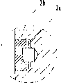
Fig. 4 is the I place partial enlarged drawing of Fig. 1.
The specific embodiment
Below in conjunction with drawings and Examples the utility model is done further detailed description:
Shown in Fig. 1,2,3,4, the rotating disk 4 that comprises installation mold, be fixed on the gear wheel 3 on the rotating disk, be located at the rotating mechanism 1 that the drive gear wheel on two plates rotates, be located at the hollow rotating shaft 7 of the gear wheel on two plates, it is supporting 6 to be located at oil content on the hollow rotating shaft, and it is supporting 5 to be located at moisture on the hollow rotating shaft, is located in the hollow shaft and is connected with the oil-feed cover and the tumbler 9 of rotating rotation mandrel 8 and the rotation of driven rotary mandrel.Rotating disk is a spoke structure, is provided with the flexible feet 2 more than three thereon, and it comprises disk spring 2a and shoes 2b.The positioner 12 that also comprises rotating disk, this device comprise locating shaft 12b and drive the oil cylinder 12a of locating shaft motion, have the hole that adapts with locating shaft accordingly on rotating disk.Hollow shaft is located on two plates by cylindrical roller bearing.The rotating mechanism 1 that above-mentioned drive gear wheel rotates comprises AC servomotor 1b and gearbox 1a thereof.The tumbler 9 of rotation mandrel comprises that motor 9a reaches the shaft gear 9b that offers spline by its drive, has free-sliding spline accordingly on the rotation mandrel.The positioner 11 of shaft gear, this device comprise locating shaft 11b and drive the oil cylinder 11a of locating shaft motion, have the hole that adapts with locating shaft accordingly on shaft gear.Also comprise the secondary support means 14 that is located at the rotating disk on two plates, this device comprises eccentric shaft 14a and is located at roller 14b on the eccentric shaft.Also comprise the axial direction positioning device that is located at the rotating disk on two plates, this device is spacing briquetting 13.
Operation principle: (one) mould rotates back and forth for 180 °: during moulded products, finish back die sinking for the first time, rotating disk 4 drives by AC servomotor 1b and makes gear wheel 3 rotations through gearbox 1a, when forwarding 180 ° of desired locations to, does final position by positional cylinder 12a and determines; Carry out the injection second time behind the matched moulds, die sinking after finishing, the thimble oil cylinder ejects goods, and the rotating disk revolution is 180 ° then, and process is with for the first time identical.(2) core rod rotates back and forth for 180 °: the course of work is similar to (one), after mandrel 8 ejects a segment distance with core rod, oil motor drives shaft gear 9b and drives mandrel Rotate 180 °, thereby make core rod Rotate 180 °, mandrel 8 retracts original position to core rod then, is located by positional cylinder 11a, matched moulds, carry out the injection second time, die sinking ejects goods; And then repeat above-mentioned action.
Claims (10)
1, a kind of injection machine mould rotating mechanism, the rotating disk that comprises installation mold, it is characterized in that: also comprise the gear wheel (3) that is fixed on the rotating disk (4), be located at the rotating mechanism (1) that the drive gear wheel (3) on two plates rotates, be located at the hollow rotating shaft (7) of the gear wheel on two plates, be located at the oil content supporting (6) on the hollow rotating shaft, be located at the moisture supporting (5) on the hollow rotating shaft, be located in the hollow shaft and be connected with the supporting oil-feed cover of oil content and the tumbler (9) of rotating rotation mandrel (8) and the rotation of driven rotary mandrel.
2, injection machine mould rotating mechanism according to claim 1 is characterized in that: be provided with the flexible feet (2) more than three on rotating disk (4).
3, injection machine mould rotating mechanism according to claim 1 and 2 is characterized in that: flexible feet comprises disk spring (2a) and shoes (2b).
4, injection machine mould rotating mechanism according to claim 1, it is characterized in that: the positioner (12) that also comprises rotating disk, this device comprises locating shaft (12b) and drives the oil cylinder (12a) of locating shaft motion, have the hole that adapts with locating shaft accordingly on rotating disk.
5, injection machine mould rotating mechanism according to claim 1 is characterized in that: the tumbler (9) of rotation mandrel comprises that motor (9a) reaches the shaft gear of offering spline (9b) by its drive, has free-sliding spline accordingly on the rotation mandrel.
6, injection machine mould rotating mechanism according to claim 1 or 5, it is characterized in that: the positioner (11) that also comprises shaft gear, this device comprises locating shaft and drives the oil cylinder (11a) of locating shaft (11b) motion, have the hole that adapts with locating shaft accordingly on shaft gear.
7, injection machine mould rotating mechanism according to claim 1, it is characterized in that: rotating disk is a spoke structure.
8, injection machine mould rotating mechanism according to claim 1 is characterized in that: also comprise the secondary support means (14) that is located at the rotating disk on two plates, this device comprises eccentric shaft (14a) and is located at roller (14b) on the eccentric shaft.
9, injection machine mould rotating mechanism according to claim 1 is characterized in that: also comprise the axial direction positioning device that is located at the rotating disk on two plates, this device is spacing briquetting (13).
10, injection machine mould rotating mechanism according to claim 1 is characterized in that: the rotating mechanism (1) that described drive gear wheel rotates comprises AC servomotor (1b) and gearbox (1a) thereof.
Priority Applications (1)
| Application Number | Priority Date | Filing Date | Title |
|---|---|---|---|
| CN 200420071573 CN2717655Y (en) | 2004-07-14 | 2004-07-14 | Injection moulding machine die rotary mechanism |
Applications Claiming Priority (1)
| Application Number | Priority Date | Filing Date | Title |
|---|---|---|---|
| CN 200420071573 CN2717655Y (en) | 2004-07-14 | 2004-07-14 | Injection moulding machine die rotary mechanism |
Publications (1)
| Publication Number | Publication Date |
|---|---|
| CN2717655Y true CN2717655Y (en) | 2005-08-17 |
Family
ID=34893713
Family Applications (1)
| Application Number | Title | Priority Date | Filing Date |
|---|---|---|---|
| CN 200420071573 Expired - Fee Related CN2717655Y (en) | 2004-07-14 | 2004-07-14 | Injection moulding machine die rotary mechanism |
Country Status (1)
| Country | Link |
|---|---|
| CN (1) | CN2717655Y (en) |
Cited By (5)
| Publication number | Priority date | Publication date | Assignee | Title |
|---|---|---|---|---|
| CN102078937A (en) * | 2010-12-02 | 2011-06-01 | 苏州苏铸成套装备制造有限公司 | Mould rotating device |
| CN107738403A (en) * | 2017-09-27 | 2018-02-27 | 海天塑机集团有限公司 | A kind of rotating disk, rotating shaft share model structure |
| CN108394063A (en) * | 2018-03-29 | 2018-08-14 | 广东伊之密精密注压科技有限公司 | A kind of contactless rotating-table apparatus of ejection certainly of multi-component injection molding machine |
| CN109366866A (en) * | 2018-10-25 | 2019-02-22 | 海天塑机集团有限公司 | A kind of novel turntable, shaft common type multiple groups part injection molding machine |
| CN110774520A (en) * | 2019-10-24 | 2020-02-11 | 叶万辉 | Rotary disc type multi-component injection molding die assembly equipment |
-
2004
- 2004-07-14 CN CN 200420071573 patent/CN2717655Y/en not_active Expired - Fee Related
Cited By (5)
| Publication number | Priority date | Publication date | Assignee | Title |
|---|---|---|---|---|
| CN102078937A (en) * | 2010-12-02 | 2011-06-01 | 苏州苏铸成套装备制造有限公司 | Mould rotating device |
| CN107738403A (en) * | 2017-09-27 | 2018-02-27 | 海天塑机集团有限公司 | A kind of rotating disk, rotating shaft share model structure |
| CN108394063A (en) * | 2018-03-29 | 2018-08-14 | 广东伊之密精密注压科技有限公司 | A kind of contactless rotating-table apparatus of ejection certainly of multi-component injection molding machine |
| CN109366866A (en) * | 2018-10-25 | 2019-02-22 | 海天塑机集团有限公司 | A kind of novel turntable, shaft common type multiple groups part injection molding machine |
| CN110774520A (en) * | 2019-10-24 | 2020-02-11 | 叶万辉 | Rotary disc type multi-component injection molding die assembly equipment |
Similar Documents
| Publication | Publication Date | Title |
|---|---|---|
| CN101804432B (en) | Rolling ring machine with internally supported rim | |
| CN100430166C (en) | Hemming press driven by a screw and servo motor | |
| CN200984751Y (en) | Stamping and rotating type nylon flat ribbon punch | |
| CN102145367A (en) | Metal ring machining device and using method thereof | |
| CN2717655Y (en) | Injection moulding machine die rotary mechanism | |
| CN110480540B (en) | Dot-matrix flexible cylinder sleeve excircle fixture | |
| CN202045902U (en) | Rotary table device | |
| CN204604966U (en) | The transmission device of Pressesservo | |
| CN102332791A (en) | Motor stator turnover device | |
| CN114474314B (en) | Ceramic roller press with multi-rotating-head switching function | |
| CN208743453U (en) | A kind of spinning apparatus | |
| CN102416673B (en) | Multi-station rotary workbench type cutting forming machine | |
| CN115582470A (en) | Engine oil pan manufacturing device | |
| CN204222213U (en) | The main drive system of numerical control servo punch press | |
| CN2305261Y (en) | Hydraulic punching forging machine | |
| CN204712691U (en) | A kind of diesel engine flywheel wordline mixing roller printing equipment | |
| CN205660018U (en) | A equipment for roll extrusion storing jar | |
| CN202200561U (en) | Clutch-type screw-press transmission mechanism | |
| CN201068912Y (en) | Hydraulic transmission stroke positioning automatic control device | |
| CN206884233U (en) | The pressing equipment of automatic oil feed | |
| CN202123150U (en) | Multifunctional integrated pipe bender | |
| CN206579011U (en) | Thermoplastic elastomer (TPE) is with direct-connected non-to the guide tracked pellet device of cardioid | |
| CN219703129U (en) | Novel closed double-point eccentric crankshaft punching machine of secondary gear speed reducing mechanism | |
| CN101033779A (en) | Overrunning clutch device used in vehicle | |
| CN201261268Y (en) | Lever type stretching stamping machine tool |
Legal Events
| Date | Code | Title | Description |
|---|---|---|---|
| C14 | Grant of patent or utility model | ||
| GR01 | Patent grant | ||
| C17 | Cessation of patent right | ||
| CF01 | Termination of patent right due to non-payment of annual fee |
Granted publication date: 20050817 Termination date: 20100714 |