CN2703209Y - Exhauster for removing cooking fumes capable of automatic lifting and lowering exhausting mouth - Google Patents
Exhauster for removing cooking fumes capable of automatic lifting and lowering exhausting mouth Download PDFInfo
- Publication number
- CN2703209Y CN2703209Y CN 200420050232 CN200420050232U CN2703209Y CN 2703209 Y CN2703209 Y CN 2703209Y CN 200420050232 CN200420050232 CN 200420050232 CN 200420050232 U CN200420050232 U CN 200420050232U CN 2703209 Y CN2703209 Y CN 2703209Y
- Authority
- CN
- China
- Prior art keywords
- automatic lifting
- oil
- air scoop
- suction inlet
- smoke exhaust
- Prior art date
- Legal status (The legal status is an assumption and is not a legal conclusion. Google has not performed a legal analysis and makes no representation as to the accuracy of the status listed.)
- Expired - Fee Related
Links
Images

Abstract
The utility model relates to an exhauster for removing cooking fumes capable of automatic lifting and lowering exhausting mouth, belonging to an exhaust type exhauster, in particularly to an exhauster for removing cooking fumes capable of automatic lifting and lowering an exhausting mouth. The utility model comprises a host machine box, an exhausting oil and smoke power device, a gas discharge channel for oil and smoke and a switch electric control circuit, a flexible channel is provided between the host machine box and a guide gas cover, and an exhausting mouth can be adjusted by the flexible channel, thus making the guide gas cover of the exhauster at the optimum position off kitchen tools, so oil and smoke can be exhausted neatly before oil and smoke diffuse. Because the position of the guide gas cover is reduced, the front-and-back distance can be shortened, thus preventing the head from being touched and users' operation from being impeded, and a transparent front panel turnover and an angular bucket-shaped cover provides better collimation line and optimum design of guide oil paths, so dropping oil can flow into an oil holder farthest. The arrangement of exhaust fans in series follows the principle of advanced aerodynamics, so high-speed air stream and lowest noise can be generated, greatly lifting the release rate of oil smoke, discharge gas and peculiar smell.
Description
Technical field
The utility model belongs to a kind of exhausting type range hood, but especially a kind of smoke exhaust ventilator of automatic lifting suction inlet.
Background technology
Existing all kinds of smoke exhaust ventilator mainly comprises mainframe box, fume exhaust aerodynamic device, parts such as soot gas discharge-channel and switch electric control circuit.Yet because air entry is higher apart from the kitchen range top, even therefore big power arranged again, the oil smoke suction that pot motor is also difficult bigger with proportion is clean, also can strengthen noise pollution on the contrary.If the installation site of existing smoke exhaust ventilator is reduced, though suction can suitably improve, air scoop can be run into user's head again, and hinders its sight line and operation.And along with the raising of people's living standard, interior decoration is superior day by day, and kitchen fume has become the trouble of headache, and oil smoke not only pollutes indoor environment, also has carcinogen, directly influences people's life and health.
According to the column prompting of the 10th cover family of on 02 17th, 2004 CCTVs, cook, cooking the amount that the pernicious gas that 1 day 3 meal is inhaled is inhaled 2 cigarette packages suitable every day in the kitchen of exhaust difference.
Nine in the article " 10 are boiled the woman " of on 02 10th, 2004 " Modern Family's newspaper " publication is fat all to be the misfortune that " liquor-saturated oil " is invited, say: " woman boils for a long time after the work of kitchen in a lot of families; headache, uncomfortable in chest, symptoms such as eye is itched, nasal obstruction, tinnitus just can occur, serious also can cause insomnia, failure of memory, bronchitis and pneumonia.The expert studies have shown that, this phenomenon is that the oil smoke when cooking causes.The oil temperature was too high when cause was cooked, and made the rapid pyrolysis dehydration of glycerine composition in the grease, generated " methacrylaldehyde "." methacrylaldehyde " not only can make the people feel that the larynx dry eyes are puckery as the ethanol in the wine, produces " signs of getting drunk ", but also can cause the body fat mass in human body metabolism not normal, makes a large amount of fat accumulations in hypodermis.Aggregate data shows, though a lot of kitchens worker's appearance seems that the body expanded letter is fat, the whole face floodlight can not illustrate their true health status.On the contrary, the ratio of suffering from cardiovascular and respiratory disease is apparently higher than other people, and this all is that existing smoke exhaust ventilator can't cause by suction absolute oil cigarette.Therefore people wish to have a kind of really thoroughly smoke exhaust ventilator of emptying oil smoke appearance.
Summary of the invention
The utility model is intended to overcome the shortcoming of above-mentioned existing smoke exhaust ventilator, provides a kind of fume exhaust performance good, the smoke exhaust ventilator that noise is low again.
The utility model is provided with mainframe box, fume exhaust aerodynamic device, soot gas discharge-channel and switch electric control circuit, below the mainframe box and air scoop above between be provided with scalable passage so that adjust the optimum height of air scoop.Preferably the main exhaust fan is located at the afterbody of blast pipe, another exhaust fan is located in the mainframe box.
Can adopt at least two inside and outside sleeve pipes of joint or cover bucket, perhaps folding telescopic structure at the scalable passage below the mainframe box and between above the air scoop.Air scoop adopts oblique bucket shape or flared structure, and the gradient of air scoop is 10~45 °, is preferably 25~35 °.The front portion of air scoop is preferably adopted and can be stirred structural design, and adopts transparent material plate.In addition establish oil holder bottom at air scoop.
Obviously, compare with existing smoke exhaust ventilator, air entry of the present utility model can be in from the position of kitchen range the best the air scoop of smoke exhaust ventilator by the adjustment of scalable passage, therefore can be before the oil smoke diffusion that its suction is clean.Because longitudinal separation can be shortened in the position that has reduced air scoop, the operation that prevents to brush up against head and hinder the user; Transparent preceding turnover panel and oblique bucket shape cover can provide sight line and best Oil Guide path design preferably, and oil dripping can be flow in the oil holder to greatest extent.The ranking method of tandem exhaust fan is the aerodynamic principle according to the advanced person, can produce high speed airflow and minimum noise, and the emission index of oil smoke, waste gas, peculiar smell is promoted significantly.
Description of drawings
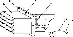
Fig. 1 is the structural representation of the utility model embodiment.
Fig. 2 is located at the schematic appearance of the exhaust fan of blast pipe afterbody for the utility model embodiment.
Fig. 3 installs and uses view for the utility model embodiment.
The specific embodiment
Following examples will be further described the utility model in conjunction with the accompanying drawings.
As Figure 1-3, the utility model is provided with mainframe box 1, fume exhaust aerodynamic device, soot gas discharge-channel and switch electric control circuit.Exhaust outlet 8 is established on the top of mainframe box 1.The fume exhaust aerodynamic device comprises to be located at the exhaust fan in the mainframe box 1 and to be used for the miniature variable speed electric motors, particularly of scalable passage, and the exhaust fan 12 of being located at blast pipe 9 afterbodys.The soot gas discharge-channel comprises air scoop 4, scalable passage (being made up of interior cover bucket 2 and 3 liang of joints of air entry overcoat bucket), blast pipe 9 etc.Air scoop 4 is oblique bucket shape, the angle of inclination is 25~35 °, the front portion of air scoop 4 for can on turn over transparent panel 5, can upwards overturn, be convenient to operation, the top of air scoop 4 connects air entry overcoat bucket 3, the top of interior cover bucket 2 connects the below of mainframe box 1, can establish 1 T shape tooth bar 17 at the rear portion of overcoat bucket 3, move, reach the purpose of adjusting the air scoop height by overcoat bucket easy on and off in the miniature variable speed electric motors, particularly control in the mainframe box 1.Rear side at air scoop 4 is provided with illuminating lamp 18, is provided with in the lower end of air scoop to contain lubricating cup 19.The exhaust outlet 8 on following termination mainframe box 1 top of blast pipe 9, the upper end connects exhaust fan 12.When not needing too big suction, can only open exhaust fan 12, can reduce the interference of noise on human like this.When the big suction of needs, can open exhaust fan 12 and be located at exhaust fan in the mainframe box.Exhaust fan 12 can be fixed on the wall by the screw on the spacing fixed frame 11 10.
The switch electric control circuit adopts existing custom circuit, and gauge tap 6, button 7, plug 13 and 15, socket 16, power lead 14 and 20, indicator lamp 21 etc. can be provided with in position.
Claims (8)
- But 1 automatic lifting suction inlet smoke exhaust ventilator, be provided with mainframe box, fume exhaust aerodynamic device, soot gas discharge-channel and switch electric control circuit, it is characterized in that below the mainframe box and air scoop above between be provided with the scalable passage that is used to adjust the air scoop height.
- But 2, automatic lifting suction inlet smoke exhaust ventilator as claimed in claim 1 is characterized in that the main exhaust fan is located at the afterbody of blast pipe, and another exhaust fan is located in the mainframe box.
- But 3, automatic lifting suction inlet smoke exhaust ventilator as claimed in claim 1 is characterized in that adopting at least two inside and outside sleeve pipes of joint or cover bucket at the scalable passage below the mainframe box and between above the air scoop, or the folding telescopic structure.
- But 4, automatic lifting suction inlet smoke exhaust ventilator as claimed in claim 1 is characterized in that air scoop adopts oblique bucket shape or flared structure.
- But, it is characterized in that the front portion employing of air scoop can be stirred structural design, and adopt transparent material plate 5, as claim 1 or 4 described automatic lifting suction inlet smoke exhaust ventilators.
- But 6, automatic lifting suction inlet smoke exhaust ventilator as claimed in claim 1 is characterized in that establishing oil holder bottom at air scoop.
- But 7, automatic lifting suction inlet smoke exhaust ventilator as claimed in claim 1, the gradient that it is characterized in that air scoop is 10~45 °.
- But 8, automatic lifting suction inlet smoke exhaust ventilator as claimed in claim 1, the gradient that it is characterized in that air scoop is 25~35 °.
Priority Applications (1)
| Application Number | Priority Date | Filing Date | Title |
|---|---|---|---|
| CN 200420050232 CN2703209Y (en) | 2004-04-20 | 2004-04-20 | Exhauster for removing cooking fumes capable of automatic lifting and lowering exhausting mouth |
Applications Claiming Priority (1)
| Application Number | Priority Date | Filing Date | Title |
|---|---|---|---|
| CN 200420050232 CN2703209Y (en) | 2004-04-20 | 2004-04-20 | Exhauster for removing cooking fumes capable of automatic lifting and lowering exhausting mouth |
Publications (1)
| Publication Number | Publication Date |
|---|---|
| CN2703209Y true CN2703209Y (en) | 2005-06-01 |
Family
ID=34776828
Family Applications (1)
| Application Number | Title | Priority Date | Filing Date |
|---|---|---|---|
| CN 200420050232 Expired - Fee Related CN2703209Y (en) | 2004-04-20 | 2004-04-20 | Exhauster for removing cooking fumes capable of automatic lifting and lowering exhausting mouth |
Country Status (1)
| Country | Link |
|---|---|
| CN (1) | CN2703209Y (en) |
Cited By (2)
| Publication number | Priority date | Publication date | Assignee | Title |
|---|---|---|---|---|
| CN103148526A (en) * | 2013-03-26 | 2013-06-12 | 罗纯力 | Smoke suction machine as well as cabinet and motor caravan including smoke suction machine |
| WO2013107102A1 (en) * | 2012-01-19 | 2013-07-25 | Yang Chengyuan | Electric lifting-type range hood |
-
2004
- 2004-04-20 CN CN 200420050232 patent/CN2703209Y/en not_active Expired - Fee Related
Cited By (2)
| Publication number | Priority date | Publication date | Assignee | Title |
|---|---|---|---|---|
| WO2013107102A1 (en) * | 2012-01-19 | 2013-07-25 | Yang Chengyuan | Electric lifting-type range hood |
| CN103148526A (en) * | 2013-03-26 | 2013-06-12 | 罗纯力 | Smoke suction machine as well as cabinet and motor caravan including smoke suction machine |
Similar Documents
| Publication | Publication Date | Title |
|---|---|---|
| CN206831604U (en) | A kind of smoke exhaust ventilator of cigarette stove linkage | |
| CN202692203U (en) | Telescopic smoke exhaust ventilator | |
| CN205090463U (en) | Can hide lampblack absorber of installation | |
| CN201497054U (en) | Automatic side-suction lifting kitchen ventilator | |
| CN2703209Y (en) | Exhauster for removing cooking fumes capable of automatic lifting and lowering exhausting mouth | |
| CN206269198U (en) | A kind of Integral ceiling Multifunctional kitchen air purifier | |
| CN201819284U (en) | Range hood | |
| CN201182369Y (en) | Integrated kitchen tool | |
| CN206861654U (en) | A kind of integrated kitchen range air intake device | |
| CN205191675U (en) | Integrated kitchen with water conservancy diversion function | |
| CN2816633Y (en) | Gas-flow-seled type kitchen hood | |
| CN112113258A (en) | Integrated stove with oil smoke purification and odor removal functions and using method thereof | |
| CN208205150U (en) | A kind of ultrathin type bottom suction type kitchen ventilator | |
| CN203099956U (en) | Side-extraction up-exhaust extractor hood | |
| CN203068582U (en) | Novel environment protection cooking stove | |
| CN2901108Y (en) | Bottom exhaust side sucking adjustable smoke collecting cover angle fume exhaust fan | |
| CN215295002U (en) | Integrated kitchen with adjustable collection petticoat pipe angle | |
| CN201028662Y (en) | Damp sheet type oil smoke isolating kitchen range | |
| CN219797311U (en) | Concealed type smoke machine | |
| CN2155509Y (en) | Improved smoke suction mouth structure of cooking fume extractor | |
| CN202813522U (en) | Range hood | |
| CN214536326U (en) | Integrated kitchen | |
| CN214307253U (en) | Integrated kitchen with oil smoke purifies removes flavor function | |
| CN209026904U (en) | Fume exhaust fan | |
| CN213810776U (en) | Smoke guide structure for integrated kitchen range |
Legal Events
| Date | Code | Title | Description |
|---|---|---|---|
| C14 | Grant of patent or utility model | ||
| GR01 | Patent grant | ||
| C19 | Lapse of patent right due to non-payment of the annual fee | ||
| CF01 | Termination of patent right due to non-payment of annual fee |