CN2595485Y - Poly porous punching machine - Google Patents
Poly porous punching machine Download PDFInfo
- Publication number
- CN2595485Y CN2595485Y CN 03211126 CN03211126U CN2595485Y CN 2595485 Y CN2595485 Y CN 2595485Y CN 03211126 CN03211126 CN 03211126 CN 03211126 U CN03211126 U CN 03211126U CN 2595485 Y CN2595485 Y CN 2595485Y
- Authority
- CN
- China
- Prior art keywords
- guide
- fixed
- plate
- guiding
- drift
- Prior art date
- Legal status (The legal status is an assumption and is not a legal conclusion. Google has not performed a legal analysis and makes no representation as to the accuracy of the status listed.)
- Expired - Fee Related
Links
Images
Abstract
The utility model relates to a microporous punching machine, which belongs to the technical field of stamping machine tools. The utility model comprises a tool body, a working table, a guide bracket, a guide transverse beam, a hydraulic oil cylinder, a mould, and a hydraulic control system, wherein, the frame type tool body is formed into an integral body by welding section steel; the guide bracket is fixed on the working table of the tool body by screw bolts, and the middle of the guide bracket is provided with the guide transverse beam; the hydraulic oil cylinder which is arranged on the upper surface of the tool body is fixedly connected with the guide transverse beam by a connecting rod, so that the guide transverse beam can move up and down on a guide upright post; the mould is arranged on a lower fixed plate of the guide bracket, and the mould and an upper mould plate are fixed on the guide transverse beam; a punch is fixed on the fixed plate by cast iron glue, the fixed plate is fixed with the upper mould plate by screws, and the punch is glidingly matched with the guide plate; the upper mould plate and the guide plate are glidingly matched with a guide post which is fixed on a lower mould plate. The utility model has the advantages of simple structure, reliable operation, simple processing technology, and low cost. The utility model also has the advantage that micropores can be processed on soft material and steel plates, wherein, the thickness of the steel plates is smaller than 1.2 mm.
Description
Technical field
The utility model belongs to the press machine technical field, particularly a kind of many micropores machine tool for punching.
Background technology
At present, laser and mechanical stamping processing is generally adopted in domestic microporous production and processing, the production cost height of Laser Processing, when adopting mechanical stamping to process many micropores on steel plate, because punch diameter is about Φ 1mm, punching is apart from 3.5-5mm, one-off hole-piercing quantity is many of 100-200, Mould Machining required precision to punching is high especially, and fixing of little drift is more difficult, when the employing low-melting alloy that has is poured into a mould fixedly, but little drift easy deformation, technological effect is also bad.
The utility model content
The purpose of this utility model is to solve the actual techniques problem that exists in present many micropores production and processing, and a kind of simple in structure, many micropores perforating press that processing cost is low is provided.
The utility model is made up of lathe bed, workbench, guiding trestle, guiding crossbeam, hydraulic jack, connecting rod, guide upright post, mould, guide pin bushing, drift, spring, cope match-plate pattern, fixed head, die plate, guide plate, lower bolster, lead, fairlead and hydraulic control system.The frame-type lathe bed is welded by shaped steel; guiding trestle is integral by guide upright post is fixedly connected by last bottom plate; be provided with the guiding crossbeam in the middle of it; and with the guide upright post sliding fit; guiding trestle is fixed by bolts on the workbench of lathe bed; hydraulic jack is arranged on above the lathe bed; its piston rod is fixedlyed connected with the guiding crossbeam by connecting rod; the guiding crossbeam is moved up and down on guide upright post; the lead of described mould is fixed on the lower bolster; cope match-plate pattern and guide plate are respectively by guide pin bushing and fairlead and lead sliding fit; drift is fixed on the fixed head by cast iron glue; fixed head is fixed on the cope match-plate pattern by screw; drift and guide plate sliding fit; and the hole of drift and die plate is aligned by guide plate; drift is played guiding and protective effect; four die plates are fixed on the lower bolster by screw; spring is arranged between cope match-plate pattern and the guide plate; make guide plate be subjected to downward spring pressure all the time; spacing by screw; cope match-plate pattern is fixed by bolts on the guiding crossbeam, and lower bolster is fixed by bolts on the bottom plate of guiding trestle.Owing to adopt said structure, the utlity model has following advantage:
1, simple in structure, reliable operation, production efficiency height;
2, processing technology is simple, low cost of manufacture;
3, can go up the many micropores of processing at soft material and steel plate (below the thickness 1.2mm).
Description of drawings
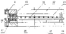
Fig. 1 is a structural representation of the present utility model;
Fig. 2 is the structural representation of the utility model mould;
Among the figure: 1 lathe bed, 2 workbench, 3 guiding trestles, 4 guiding crossbeams, 5 hydraulic jacks, 6 connecting rods, 7 guide upright posts, 8 moulds, 9 guide pin bushings, 10 drifts, 11 springs, 12 cope match-plate patterns, 13 fixed heads, 14 die plates, 15 guide plates, 16 lower bolsters, 17 leads, 18 fairleads.
The specific embodiment
As depicted in figs. 1 and 2, a kind of many micropores perforating press comprises lathe bed 1, workbench 2, guiding trestle 3, guiding crossbeam 4, hydraulic jack 5, connecting rod 6, mould 8, drift 10, cope match-plate pattern 12, fixed head 13, die plate 14, guide plate 15, lower bolster 16 and lead 17.Frame-type lathe bed 1 is integrally welded by shaped steel, guiding trestle 3 is fixedly connected by two guide upright posts 7 by last bottom plate, be provided with guiding crossbeam 4 in the middle of it, and with guide upright post 7 sliding fits, guiding trestle 3 is fixed by bolts on the workbench 2 of lathe bed 1, hydraulic jack 5 is fixed on above the lathe bed 1 by screw, its piston rod is fixedlyed connected with guiding crossbeam 4 by connecting rod 6, guiding crossbeam 4 is moved up and down on guide upright post 7, the lead 17 of mould 8 is fixed on the lower bolster 16, cope match-plate pattern 12 and guide plate 15 are respectively by guide pin bushing 9 and fairlead 18 and lead 17 sliding fits, drift 10 is fixed on the fixed head 13 by cast iron glue, than effective with the low-melting alloy technique for fixing, fixed head 13 is screwed on cope match-plate pattern 12, drift 10 and guide plate 15 sliding fits, and a little drift 10 and more than 100 punch die hole of die plate 14 are aligned by guide plate 15, four die plates 14 are fixed on the lower bolster 16 by screw, spring 11 is arranged between cope match-plate pattern 12 and the guide plate 15, make guide plate 15 be subjected to downward spring pressure all the time, spacing by screw, cope match-plate pattern 12 is fixed by bolts on the guiding crossbeam 4, lower bolster 16 is fixed by bolts on the bottom plate of guiding trestle 3, punch diameter is Φ 1mm, pitch of holes is 3.5mm, be the duplicate rows cross arrangement, totally 128 of drifts.Its course of work is: hydraulic jack 5 moves up and down guiding crossbeam 4 by connecting rod 6 on two guide upright posts 7, therefore the little drift 10 that drives cope match-plate pattern 12 and be fixed on the fixed head 13 is done ramming motion up and down, when moving upward, make guide plate 15 and die plate 14 leave certain interval by the stop screw that is fixed on the cope match-plate pattern 12, make punched material pass through drift; When moving downward punching, guide plate 15 contacts with die plate 14, and the drift 10 and the punch die hole of die plate 14 are aligned, and spring 11 is compressed, and guide plate 15 is motionless, and drift 10 is played guiding and protective effect all the time, finishes the one-off hole-piercing process.
Claims (3)
1, a kind of many micropores perforating press, comprise lathe bed, workbench, guiding trestle, the guiding crossbeam, hydraulic jack, connecting rod, guide upright post, mould, guide pin bushing, drift, spring, cope match-plate pattern, fixed head, die plate, guide plate, lower bolster, lead, fairlead and hydraulic control system, it is characterized in that described frame-type lathe bed is welded by shaped steel, guiding trestle is integral by guide upright post is fixedly connected by last bottom plate, be provided with the guiding crossbeam in the middle of it, and with the guide upright post sliding fit, guiding trestle is fixed by bolts on the workbench of lathe bed, hydraulic jack is arranged on above the lathe bed, its piston rod is fixedlyed connected with the guiding crossbeam by connecting rod, the guiding crossbeam is moved up and down on guide upright post, the lead of described mould is fixed on the lower bolster, cope match-plate pattern and guide plate are respectively by guide pin bushing and fairlead and lead sliding fit, die plate is fixed on the lower bolster by screw, spring is arranged between cope match-plate pattern and the guide plate, make guide plate be subjected to downward spring pressure all the time, spacing by screw, cope match-plate pattern is fixed by bolts on the guiding crossbeam, and lower bolster is fixed by bolts on the bottom plate of guiding trestle.
2, many micropores perforating press as claimed in claim 1, its characteristics be described drift cylinder iron glue be fixed on the fixed head, fixed head is fixed on the cope match-plate pattern by screw.
3, many micropores perforating press as claimed in claim 1, its characteristics are that described guide plate plays guiding and protective effect to drift, aligns drift and punch die hole, drift and guide plate sliding fit.
Priority Applications (1)
| Application Number | Priority Date | Filing Date | Title |
|---|---|---|---|
| CN 03211126 CN2595485Y (en) | 2003-01-24 | 2003-01-24 | Poly porous punching machine |
Applications Claiming Priority (1)
| Application Number | Priority Date | Filing Date | Title |
|---|---|---|---|
| CN 03211126 CN2595485Y (en) | 2003-01-24 | 2003-01-24 | Poly porous punching machine |
Publications (1)
| Publication Number | Publication Date |
|---|---|
| CN2595485Y true CN2595485Y (en) | 2003-12-31 |
Family
ID=33754264
Family Applications (1)
| Application Number | Title | Priority Date | Filing Date |
|---|---|---|---|
| CN 03211126 Expired - Fee Related CN2595485Y (en) | 2003-01-24 | 2003-01-24 | Poly porous punching machine |
Country Status (1)
| Country | Link |
|---|---|
| CN (1) | CN2595485Y (en) |
Cited By (4)
| Publication number | Priority date | Publication date | Assignee | Title |
|---|---|---|---|---|
| CN101406914B (en) * | 2008-11-28 | 2010-06-16 | 哈尔滨工业大学 | Micro-perforating die |
| CN102151798A (en) * | 2010-11-16 | 2011-08-17 | 苏州苏铸成套装备制造有限公司 | Lifting device |
| CN103920793A (en) * | 2014-04-17 | 2014-07-16 | 上海华世邦精密模具有限公司 | High-precision microporous plate punching precise mold |
| CN107053326A (en) * | 2016-12-27 | 2017-08-18 | 上海华世邦模具科技股份有限公司 | The environmentally friendly noise reduction sheet material processing mold of cellular ultramicropore |
-
2003
- 2003-01-24 CN CN 03211126 patent/CN2595485Y/en not_active Expired - Fee Related
Cited By (5)
| Publication number | Priority date | Publication date | Assignee | Title |
|---|---|---|---|---|
| CN101406914B (en) * | 2008-11-28 | 2010-06-16 | 哈尔滨工业大学 | Micro-perforating die |
| CN102151798A (en) * | 2010-11-16 | 2011-08-17 | 苏州苏铸成套装备制造有限公司 | Lifting device |
| CN103920793A (en) * | 2014-04-17 | 2014-07-16 | 上海华世邦精密模具有限公司 | High-precision microporous plate punching precise mold |
| CN103920793B (en) * | 2014-04-17 | 2016-05-25 | 上海华世邦精密模具有限公司 | A kind of high-precision micropore plate punching precision die |
| CN107053326A (en) * | 2016-12-27 | 2017-08-18 | 上海华世邦模具科技股份有限公司 | The environmentally friendly noise reduction sheet material processing mold of cellular ultramicropore |
Similar Documents
| Publication | Publication Date | Title |
|---|---|---|
| CN201702549U (en) | O-type ring pressing-in device | |
| CN202498148U (en) | Stamping part mould | |
| CN2595485Y (en) | Poly porous punching machine | |
| CN202123147U (en) | Dedicated mould for punching lower support of automotive damper | |
| CN203410044U (en) | Press machine of long workbench | |
| CN201313446Y (en) | Cylinder-shaped work piece fast labeling device | |
| CN217990634U (en) | Punching and flanging device | |
| CN218555315U (en) | Locking rocking arm post forming die | |
| CN202137254U (en) | Auxiliary die of die for automobile side wall outer plates | |
| CN212495144U (en) | Forging device with ejection mechanism | |
| CN210497835U (en) | Stamping equipment is used in automobile parts processing | |
| CN212442841U (en) | Aluminum alloy stamping flanging composite die | |
| CN102000758A (en) | Falling round die for forging hydraulic press | |
| CN2317981Y (en) | Multi-working-position busbar-processing hydraulic machine | |
| CN210208482U (en) | Forging press | |
| CN208322055U (en) | A kind of injection mechanism of die-casting machine | |
| CN207271902U (en) | A kind of high accuracy anti-tripping waste stamping die | |
| CN216226425U (en) | Punching die for mounting fan-shaped corrugated plate | |
| CN201324792Y (en) | Punching device of bridge plate production line | |
| CN201361657Y (en) | Multiunit mould | |
| CN220216445U (en) | Precise piece rounding die | |
| CN220279858U (en) | Stamping die is used in circuit board production | |
| CN219851916U (en) | Hydraulic press for ship accessory machining device | |
| CN218138511U (en) | Carving machine for punching glass fiber reinforced plastic pull rod | |
| CN210615113U (en) | Printer die device |
Legal Events
| Date | Code | Title | Description |
|---|---|---|---|
| C14 | Grant of patent or utility model | ||
| GR01 | Patent grant | ||
| C19 | Lapse of patent right due to non-payment of the annual fee | ||
| CF01 | Termination of patent right due to non-payment of annual fee |