CN2463243Y - Theft-and hijack-preventing system for vehicle - Google Patents
Theft-and hijack-preventing system for vehicle Download PDFInfo
- Publication number
- CN2463243Y CN2463243Y CN00234587U CN00234587U CN2463243Y CN 2463243 Y CN2463243 Y CN 2463243Y CN 00234587 U CN00234587 U CN 00234587U CN 00234587 U CN00234587 U CN 00234587U CN 2463243 Y CN2463243 Y CN 2463243Y
- Authority
- CN
- China
- Prior art keywords
- lock
- slingshot
- moving
- pellet shot
- electromagnetic valve
- Prior art date
- Legal status (The legal status is an assumption and is not a legal conclusion. Google has not performed a legal analysis and makes no representation as to the accuracy of the status listed.)
- Expired - Fee Related
Links
- 239000007788 liquid Substances 0.000 claims abstract description 25
- 239000008188 pellet Substances 0.000 claims description 58
- 239000012212 insulator Substances 0.000 claims description 38
- 238000010521 absorption reaction Methods 0.000 claims description 12
- XEEYBQQBJWHFJM-UHFFFAOYSA-N Iron Chemical compound [Fe] XEEYBQQBJWHFJM-UHFFFAOYSA-N 0.000 claims description 8
- 230000008878 coupling Effects 0.000 claims description 7
- 238000010168 coupling process Methods 0.000 claims description 7
- 238000005859 coupling reaction Methods 0.000 claims description 7
- 239000004020 conductor Substances 0.000 claims description 5
- 238000006073 displacement reaction Methods 0.000 claims description 5
- 239000003063 flame retardant Substances 0.000 claims description 4
- 229910052742 iron Inorganic materials 0.000 claims description 4
- 230000001105 regulatory effect Effects 0.000 claims description 4
- 229910001338 liquidmetal Inorganic materials 0.000 claims description 3
- QSHDDOUJBYECFT-UHFFFAOYSA-N mercury Chemical compound [Hg] QSHDDOUJBYECFT-UHFFFAOYSA-N 0.000 claims description 3
- 229910052753 mercury Inorganic materials 0.000 claims description 3
- 238000009413 insulation Methods 0.000 claims 1
- 230000002265 prevention Effects 0.000 abstract 1
- 239000003921 oil Substances 0.000 description 32
- 230000000694 effects Effects 0.000 description 22
- 239000000446 fuel Substances 0.000 description 7
- 230000005611 electricity Effects 0.000 description 5
- 230000006378 damage Effects 0.000 description 4
- 238000010008 shearing Methods 0.000 description 4
- 230000001360 synchronised effect Effects 0.000 description 4
- 206010033799 Paralysis Diseases 0.000 description 3
- 230000009471 action Effects 0.000 description 3
- 239000010705 motor oil Substances 0.000 description 3
- 230000001681 protective effect Effects 0.000 description 3
- 229910000831 Steel Inorganic materials 0.000 description 2
- 208000027418 Wounds and injury Diseases 0.000 description 2
- 230000007812 deficiency Effects 0.000 description 2
- 239000002283 diesel fuel Substances 0.000 description 2
- 238000005516 engineering process Methods 0.000 description 2
- 239000000945 filler Substances 0.000 description 2
- 239000012467 final product Substances 0.000 description 2
- 210000004907 gland Anatomy 0.000 description 2
- 229910052751 metal Inorganic materials 0.000 description 2
- 239000002184 metal Substances 0.000 description 2
- 238000000034 method Methods 0.000 description 2
- 238000012544 monitoring process Methods 0.000 description 2
- 230000008569 process Effects 0.000 description 2
- 239000007858 starting material Substances 0.000 description 2
- 239000010959 steel Substances 0.000 description 2
- 206010009696 Clumsiness Diseases 0.000 description 1
- 206010011878 Deafness Diseases 0.000 description 1
- 241000755266 Kathetostoma giganteum Species 0.000 description 1
- 230000015572 biosynthetic process Effects 0.000 description 1
- 239000003795 chemical substances by application Substances 0.000 description 1
- 238000004891 communication Methods 0.000 description 1
- 230000001276 controlling effect Effects 0.000 description 1
- 230000007797 corrosion Effects 0.000 description 1
- 238000005260 corrosion Methods 0.000 description 1
- 238000005336 cracking Methods 0.000 description 1
- 230000009849 deactivation Effects 0.000 description 1
- 238000013461 design Methods 0.000 description 1
- 239000008151 electrolyte solution Substances 0.000 description 1
- 239000012530 fluid Substances 0.000 description 1
- 208000014674 injury Diseases 0.000 description 1
- 238000003780 insertion Methods 0.000 description 1
- 230000037431 insertion Effects 0.000 description 1
- 238000009434 installation Methods 0.000 description 1
- 239000011810 insulating material Substances 0.000 description 1
- 238000012423 maintenance Methods 0.000 description 1
- 230000014759 maintenance of location Effects 0.000 description 1
- 239000000463 material Substances 0.000 description 1
- 239000007769 metal material Substances 0.000 description 1
- 230000006855 networking Effects 0.000 description 1
- 238000012856 packing Methods 0.000 description 1
- 239000003208 petroleum Substances 0.000 description 1
- 239000011148 porous material Substances 0.000 description 1
- 238000004393 prognosis Methods 0.000 description 1
- 235000002020 sage Nutrition 0.000 description 1
- 239000007787 solid Substances 0.000 description 1
- 238000005507 spraying Methods 0.000 description 1
- 230000003068 static effect Effects 0.000 description 1
- 230000002277 temperature effect Effects 0.000 description 1
- 230000007306 turnover Effects 0.000 description 1
Images


Landscapes
- Burglar Alarm Systems (AREA)
Abstract
The utility model relates to a theft-and hijack-preventing system for a vehicle. The utility model is provided with an electromagnetic valve to lock the oil way, a locking disassembly-preventing structure is arranged in a power supply converting device which controls the circuit of the electromagnetic valve, an electromagnetic coil and a machine code lock are additionally arranged to control the position locking the breaking or connection of a movable contact bridge of the power supply converting device with the power source of the electromagnetic valve, the electromagnetic valve is connected in series with the power supply converting device through a liquid guide wire, and the electromagnetic coil in the power supply converting device is connected in series with an automatic locking switch. The utility model has the functions of pre-locking, automatic locking and prevention that the system alert state is released by the means, such as broken wire, disassembling, external forces, etc., the vehicle safety is fully ensured, and simultaneously the personal safety of a driver is ensured in maximum degree.
Description
The utility model relates to a kind of automotive safety protective system that anti-theft and anti-robbing is robbed two kinds of functions that has concurrently.
At present, known safety guard for automobile has antitheft class and the anti-class of plundering.Antitheft class has: cane lock, electronic password lock, micro computer frame hopping Car Burglar Alarm, electronic alarm, Computerized monitor system.The anti-class of plundering: apron and safety net, the anti-snatch raid device of electronics high-tension current, Multifunctional GPS warning positioning system.Cane lock is made up of mechanical lock head, steel lock body, by bearing circle, brake pedal, pedal of clutch are controlled, makes it to be operated and reaches antitheft purpose.Electronic password lock is made up of a series of electronic components, and the control ignition switch can not be activated and reach antitheft purpose.Micro computer frame hopping Car Burglar Alarm is locked the starter motor circuit by computer module, makes driving engine reach antitheft purpose by self dynamic start.Electronic alarm becomes sound generation device by electric component group, sends chimes of doom under improper action effect, frightens the resistance burglar and reaches antitheft purpose.Computerized monitor system adopts computer and public security department's computer networking, and monitoring automotive use situation reaches antitheft to purpose.Apron and safety net separate and reach the anti-purpose of plundering by baffle plate and safety net are set between driver and passenger.The anti-snatch raid device of electronics high-tension current is formed high-tension current generating means electric shock attacker by electronic component and is reached the anti-purpose of plundering.The Multifunctional GPS position fixing system is a kind of Multifunctional GPS communication system in fact, and it and 110 warnings are networked, the automobile of tracing and monitoring warning via satellite, and the rapid responding of public security department reaches the anti-purpose of plundering of prognosis.The deficiency of said apparatus is embodied in: cane lock mode clumsiness, use trouble, and damage resistance is poor, and anti-theft feature easily is disengaged; Electronic password lock takes to destroy lock body, broken line, use the high-pressure ignition wire of same model can remove rapidly that it is on the alert, can not be used to not have the diesel oil fuel automobile of ignition system; Micro computer frame hopping Car Burglar Alarm can not be used for the diesel oil fuel automobile of the pressured igniting of contracting equally, this class car need only replace starter motor startup automobile to get final product by the manpower propelling vehicle, even on the automobile of Fuel Petroleum, also perform practically no function: only in the manpower propelling vehicle, ignition lock is screwed to ignition location gets final product, this is the most common in clique's crime.Adopt broken line, walk around the demoder external source and can remove rapidly also that it is on the alert; Electronic alarm lacks necessary lock function, can not stop burglar's ignition trigger automobile, because masses' awareness property is not high, the public security police strength is limited, the masses add that the annunciator ring that often is activated at ordinary times is alert under normal condition, so even have and steal alert sending, can turn a blind eye to mostly, turn a deaf ear to, public security department also is difficult to rapid responding; Moreover as long as breaking alarm power supply or destroy annunciator itself, can remove that it is on the alert.Computerized monitor system lacks necessary locking function, and the burglar is easy to drive to flee from monitored space; The supply line of cutting off the electricity supply, this system paralyses immediately; Monitored control system must could be worked under the situation that electricity is arranged, and power consumption is big, adds itself cost height, and car owner or driver are difficult to bear mostly.Apron and safety net make in the car narrow, influence driver's spirit and even traffic safety; Force the robber to have no option, have only the apparatus of employing to rob car, do not guarantee that in fact automobile is not seized by force, also increased driver's danger in the mode of killing a person or hurting sb.'s feelings.Electronics high-voltage electric shock formula causes easily accidentally injures or related wound (injury driver during the electric shock robber), also evoke the ruffian easily and hate meaning, make and originally be reluctant to kill a person to serve as that the ruffian that robs the car mode does not do him when committing a crime and thinks, the misfortune car simply kills a person, moreover robber crime often two electricity is hindered a people more than the people, remaining more can be gone to extremes, the misfortune car that kills a person, the driver not only loses life but also lose car like this.It is advanced that the Multifunctional GPS warning positioning system seems, cracking it is easy to turn one's hand over, because it must could be worked under the situation of energising, cut off its power supply, this system paralyses immediately, and the robber just can commit a crime calmly, simultaneously owing to limited by crime zone, time and police strength situation, its effect is had a greatly reduced quality, because the GPS price factor, it promotes the use of restricted greatly especially.Make a general survey of described, known safety guard for automobile is except above-mentioned all deficiencies, also lack pre-lock and AutoLock feature without exception, stay major hidden danger to automotive safety, antitheft and anti-snatch raid device and function set up the trouble that also increased in installation, the use and burden economically separately, belong to the automotive safety protective system of passive featherwit's formula.The friendly periodical publisher of bibliography " electrotechnics " Higher Education Publishing House, " trac. " Chinese agriculture machinery press, " Audi's electron spraying system structure and principle " China Machine Press, " Jetta electrical structure and maintenance " press of Beijing Institute of Technology, " Shanghai Santana structural upright atlas " Science and Technology of Shanghai press, " the practical electronic circuit of automobile and motorcycle is made 137 examples " People's Telecon Publishing House, " friend of automobile " 2000 third phase of magazine automobile.
The purpose of this utility model provides a kind of vehicle anti-theft and anti-robbing and robs system.It can not only fully guarantee the safety on the automobile property right, can also guarantee driver's personal safety to greatest extent, can prevent effectively that the burglar from adopting all means such as disassembling, break line, use external force to remove its purpose that reaches auto theft on the alert; The function that it also has pre-lock, automatically locks, prevent the driver because of careless and lazy, carelessness not or forget that enabling anti-joyride device stays opportunity to the ruffian, guarantee that simultaneously the driver is when meeting with the robber, no matter be that body suffers accident, still be forced to or initiatively abandon car, the ruffian can't seize automobile by force, especially provides a kind of driver's personal safety and automotive safety of guaranteeing simultaneously to the driver, catches robber's best mode: initiatively wittily abandon car and report a case to the security authorities; It generally is applicable to various dissimilar automobiles, is a kind of automotive safety protective system of active sage type.
The purpose of this utility model be achieved in that system by electromagnetic valve, interface tube, power control, automatically lock switch, the function setting device is formed.The electromagnetic valve body valve seat presses together, piston, piston push rod, armature mechanical connection, and locking spring is enclosed within on the piston push rod, contacts with piston, and magnet coil and armature are in the moving position of closing of machinery; The last lower insulator of power supply change-over device presses together, and inner chamber has the acting arm on a pair of break back contact and the movable contact bridge to be in the moving disconnected or moving state that closes; The bench insulator inner chamber that automatically locks switch has a pair of break back contact, and moving contact on the T shape contact and break back contact are in the moving disconnected state of machinery; The function setting device is a common contactor; Interface tube loam cake and main body screw retention, the connected body oil inlet stretches into the interface tube oil inlet, and clamp is placed between oil-feed tube head and the main body, and oil inlet is fixed by filler, gland packing; A pair of lock screw is set, is connected and fixed electromagnetic valve valve seat and valve body, lock screw is in mechanical moving closing or moving disconnected position with the Control arm that is fixed on the armature; One mechanical cipher lock is set, and lock body is fixed on the insulator, and lock core stretches into the insulator inner chamber by the insulator mesopore, is in the moving position of closing of machinery with the movable contact bridge; In another insulator inner chamber pore location one magnet coil is set, coil is enclosed within on the push rod, and push rod one end connects an armature, and armature and magnet coil are in the moving position of closing of machinery, and push rod and movable contact bridge are in the moving position of closing of machinery; A pair of lock screw is set connects and go up lower insulator, be in the moving disconnected or moving position of closing of machinery with the Control arm at movable contact bridge two ends; Cover cavity is provided with an internal lock gas thread on interface tube, and the main body inner chamber is established an internal lock oil inlet screw thread that has a bar shaped fuel feed hole, with the interface tube oil inlet be one, the internal lock flathead screw, be screwed into from oil inlet, connect loam cake internal lock gas thread, a pair of latch is set between loam cake and the main body.Electromagnetic valve is placed in the oil circuit by interface tube.One liquid wire is set to be electrically connected the electromagnetic valve sucking coil with a break back contact in the power supply change-over device.Liquid wire fire retardant insulating pipe two ends are threaded with screw thread coupling end cap, and screw thread coupling end cap inner chamber is provided with regulating spring and adjusting piston, and adjusting piston and liquid conduction core are combined closely.Another break back contact is electrically connected with electric power incoming line in the power supply change-over device, and the magnet coil and in the power supply change-over device automatically locks switch, the function setting device is connected in parallel in the automobile circuit after connecting; Automatically lock switch and be placed on the car door door pillar of operator's compartment one side, T shape contact and car door are in mechanical moving closing or moving disconnected position.When native system stood alert, mechanical code lock stood alert, and lock core can not be operated, and the movable contact bridge is in the position of disjunction power of electromagnetic valve; Do not backed out with the Control arm control lock screw that the movable contact bridge is fixed together, power supply change-over device is in synchronous locking tamper and separates state.Electromagnetic valve is because of outage, suction disappears on the magnet coil, and piston is lived in hydraulic fluid port in the effect lower seal of locking spring, and fuel feed system stops to engine oil, while is not backed out with the Control arm control lock screw that armature is fixed together, and electromagnetic valve is in synchronous locking tamper and separates state.Because the store oil function of interface tube; automobile still can be by the retrofire designed distance of travelling, and thoroughly oil-break is flame-out then, makes the burglar take for fuel system and breaks down and initiatively abandon car; do not destroy anti-joyride device and can not go to seek, thereby protected anti-joyride device itself.When being authorized to enable automobile, at first must be by the password of setting, open coded lock, the operation lock core, the motion of lock core control movable contact bridge, the acting arm on the movable contact bridge combines with break back contact on the insulator, connect power of electromagnetic valve, the Control arm that is fixed on the movable contact bridge breaks away from the control lock screw, and lock screw can be backed out this moment, and power supply change-over device is in disassembled state; Then, unclamp lock core, lock core return under the effect of pull back spring, the movable contact bridge is return simultaneously not, pulls out random figure disc, and native system promptly is in pre-lock state.Simultaneously, the energising of electromagnetic valve sucking coil produces suction, attracts armature movement, armature drives push rod, Control arm, piston, overcomes the action of locking spring application force, and piston is opened oil inlet, fuel feed system is recovered to engine oil, but automobile is in normal operating condition.Control arm breaks away from the control lock screw simultaneously, and lock screw can be backed out, and electromagnetic valve is in disassembled state.When the inactive automobile of driver, open car door, the application force that acts on the automatic control switch T shape contact disappears, under the effect of pull back spring, moving contact on the T shape contact combines with break back contact, electromagnetic attaction coil electricity in the power supply change-over device produces attractive force, attract armature movement, armature drives push rod and acts on the movable contact bridge, acting arm on the movable contact bridge is separated with break back contact, cut off power of electromagnetic valve, the Control arm control lock screw that is fixed on the movable contact bridge is not backed out, and power supply change-over device is in synchronous locking tamper and separates state.The outage of electromagnetic valve sucking coil, suction disappears, armature, push rod, Control arm, piston, return under the effect of locking spring, piston is sealed oil inlet, and oil circuit stops to engine oil, Control arm control lock screw is not backed out, and electromagnetic valve is in synchronous locking tamper and separates state.Because the mechanical cipher tapered end locks in advance, so far native system is finished the process of automatically locking; As long as open car door, native system just automatically locks, and has solved the driver and has not careless and lazyly enabled or forget and enable anti-joyride device stays opportunity to the ruffian potential safety hazard because of neglecting; Simultaneously, when meeting with the robber, no matter be that body suffers accident to be forced to abandon car, or the driver initiatively abandons car, car door must at first be opened, native system is on the alert must to be activated, although because the store oil function of interface tube, the automobile certain distance that can also ignition trigger travels, inevitable at last thoroughly oil-break is flame-out, not only the robber robs and does not walk automobile, reports to the police on the contrary the driver with the plenty of time escape.Based on the AutoLock feature of native system, when the driver meets with the robber, needn't resist with the robber, should report a case to the security authorities by the initiatively quick-witted car of abandoning, not only can guarantee automotive safety fully, can also guarantee driver's inherently safe to greatest extent.When closing entrance door, car door acts on T shape contact, moves behind the T shape contact, and moving contact separates with break back contact, the outage of power supply change-over device sucking coil, and suction disappears, and armature, push rod break away from movable contact bridge return, and the movable contact bridge still is in the position that cuts off power of electromagnetic valve.Because native system stands alert under the situation of not having electricity, thereby has saved the energy.Native system adopts liquid wire to connect electromagnetic valve and power control, makes the ruffian can't adopt brokenly the mode of line to remove the on the alert of native system; Electromagnetic valve locking oil circuit makes the lawless person rely on automobile self power or external force all can't steal or seize by force automobile; Make native system be suitable for various types of automobiles simultaneously, the function setting device makes the driver whether enable the on the alert of native system according to the wish decision of oneself.
Owing to adopt such scheme, overcome the function of safety guard for automobile anti-theft and anti-robbing misfortune in the past and separated, device sets up separately, and damage resistance is poor, and applicable surface is narrow, poor effect, and anti-theft and anti-robbing is robbed the wretched insufficiency that function easily is disengaged; When fully guaranteeing automobile property right safety, guaranteed driver's personal safety to greatest extent.Native system all is that the mature technology science makes up cleverly except that liquid wire, and is simple in structure, cheap.
Below, the utility model is described in further detail in conjunction with the accompanying drawings and embodiments
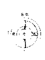
Fig. 1 is structure of the present utility model and conspectus.
Fig. 2 is the mechanical cipher lock positive view of mechanical cipher locking anti-dismantling power control setup among embodiment of the utility model.
Fig. 3 is the sectional view of Fig. 2
Fig. 4 is the A-A cutaway view of Fig. 2.
Fig. 5 is that the A of part 2 among Fig. 2 is to cutaway view.
Fig. 6 is that the A of part 3 among Fig. 2 is to view.
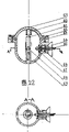
Fig. 7 is the power supply change-over device of mechanical cipher locking anti-dismantling power control setup among embodiment of the utility model and the positive view of DC electromagnet.
Fig. 8 is the sectional view of Fig. 7.
Fig. 9 is the A-A cutaway view of part 17 among Fig. 7.
Figure 10 is that the B of part 8 among Fig. 7 is to semisectional view.
Figure 11 be among Fig. 7 part 22C to view.
Figure 12 is the positive view of anti-dismounting electromagnetic valve among the embodiment of the present utility model.
Figure 13 is the sectional view of Figure 12.
Figure 14 is the A-A cutaway view of part 40 among Figure 12.
Figure 15 is that the B of part 31 among Figure 12 is to cutaway view.
Figure 16 is that the C of part 36 among Figure 12 is to view.
Figure 17 is the positive view that automatically locks switch among the embodiment of the present utility model.
Figure 18 is the sectional view of Figure 17.
Figure 19 is that the A of part 44 among Figure 17 is to view.
Figure 20 is that the B of part 41 among Figure 17 is to view.
Figure 21 is the positive view of liquid wire among the embodiment of the present utility model.
Figure 22 is the anti-positive view of shearing interface tube of the anti-dismounting of store oil type among the embodiment of the present utility model.
Figure 23 is the A-A cutaway view of Figure 22
1.2.3.4.5.6.7.8.9.10.11.1213.14.T15.16.17.18.19.20.21.22.23.24.25.26.27.28.29.30.31.32.33.34.T35.36.37.38.39.40.41.T42.43.44.45.46.47.48.49.50.51.52.53.54.55.56.57.58.59.60.61.62.63.64.65.66.67.68.69.
In Fig. 1, magnet coil (39) is by liquid wire (28 in the electromagnetic valve, 29) with the interior following break back contact (20 of power control, 21) be electrically connected, be parallel in the automobile circuit after adding the string fuse, magnet coil (23) in the power control is by plain conductor and the half garden ring break back contact (43) that automatically locks on the switch, function setting device K1 is parallel in the automobile circuit after being electrically connected in proper order and adding the string fuse, and mechanical cipher locking anti-dismantling power control setup is made up of mechanical cipher lock, power supply change-over device, DC electromagnet.The lock body of mechanical cipher lock (2) is connected and fixed with upper insulator (8) screw of power supply change-over device, lock core (1) stretches into the insulator inner chamber from the mesopore of upper insulator (8), be in mechanical moving with movable contact bridge (22) and close state, be provided with lock core pull back spring (6) between lock core (1) and the upper insulator (8); DC electromagnet is made up of magnet coil (23), push rod (25), armature (26), magnet coil (23) is fixed on lower insulator (17) inner chamber mesopore, push rod passes magnet coil (23), be connected with armature (26), armature (26) is divided into recoil spring (27), be in the moving position of closing of machinery with magnet coil (23), push rod (25) is in the moving position of closing of machinery with movable contact bridge (22).Mechanical cipher locking anti-dismantling power control setup is arranged on the place that the driver operates smoothly in the operator's compartment.Anti-dismounting electromagnetic valve links up by the indispensable parts of the automobile on anti-dismounting anti-shearing interface tube of store oil type and the oil circuit (parts that automobile can not start or travel fully after lacking, as carburettor etc.); Automatically lock switch be placed under the driver's seat or the near post or automobile center pillar of operator's compartment car door on (by driver's one side) be the best to be placed on the near post.
In Fig. 2, the lock core (1) of the mechanical cipher tapered end of mechanical cipher locking anti-dismantling power control setup is designed to T shape, rectangular guide rail sleeve on the lock core is in the chute of lock body (2) inner chamber, and restriction garden revolution each other is by the vertical displacement of snap ring (48) restriction with lock body (2); Lock body (2) has four roads by dark gradually shallow garden groove, and there is a pellet shot from a slingshot hole at the most shallow place, knob pellet shot from a slingshot (4), pellet shot from a slingshot pull back spring (5) is arranged, totally four pairs in the pellet shot from a slingshot hole; Totally four of figure discs (3), inner chamber has by low gradually high garden rail, be enclosed within last four the garden grooves of lock body (2), can rotate along the garden groove, be limited in position on the lock body (2) by snap ring (47), each figure disc (3) is gone up total ten numbers positions of 0-9,9 locking positions, 1 non-locking position, mechanical cipher lock are installed on the upper insulator (8) of power supply change-over device, and the centre is provided with lock core pull back spring (6).When four non-locking positions of four figure discs (3) being pulled out to ad-hoc location by predefined password number, knob pellet shot from a slingshot (4) is upspring under the effect of pellet shot from a slingshot pull back spring (5), this coded lock tapered end is in unlock state, press lock core (1), the effect that lock core overcomes lock core pull back spring (6) moves down, and promotes movable contact bridge (22) displacement in the power supply change-over device; Unclamp hand, random figure disc (3) is pulled out in lock core (1) reposition under lock core pull back spring (6) effect then, and the mechanical cipher lock promptly is in the lock state.
In Fig. 7, in the power supply change-over device of mechanical cipher locking anti-dismantling power control setup a direct current electromagnet is set, the magnet coil of electromagnet (23) is fixed on lower insulator (17) inner chamber mesopore place, push rod (25) passes magnet coil (23) and is connected with an armature (26), armature (26) is divided into recoil spring (27), armature (26) is in the moving position of closing of machinery with magnet coil (23), push rod (25) is in the moving position of closing of machinery with movable contact bridge (22), the last metal case (7) of power supply change-over device is made one with upper insulator (8), following metal case (12) is made one with lower insulator (17), and the two presses together then.Upper insulator (8) is provided with absorption magnet (11), last break back contact (10); Lower insulator (17) is provided with down absorption magnet (19), following break back contact (20,21), and the connection position of break back contact (20,21) down has wire guide, and movable contact bridge (22) is in mechanical moving breaking or the moving state that closes with break back contact (10,20,21).Be provided with lock screw (15) between upper insulator (8) and the lower edge body (17), have T shape pellet shot from a slingshot (14) jack on the lock screw (15), on upper insulator (8), have the pellet shot from a slingshot hole perpendicular to the direction of lock screw (15) jack, in establish T shape pellet shot from a slingshot (14), the locking spring (16), T shape pellet shot from a slingshot (14) tail end and lock screw (15) are in the moving disconnected or moving state that closes of machinery, between pellet shot from a slingshot hole and upper insulator (8) inwall, have groove, pellet shot from a slingshot pressure arm (13) stretches into the pellet shot from a slingshot hole from groove, is enclosed within on the T shape pellet shot from a slingshot (14).Absorption magnet (11,19) is used for movable contact bridge (22) and is moved to and cuts off or when connecting the state of power of electromagnetic valve, and absorption is fixing mutually with pellet shot from a slingshot pressure arm (13) or absorption arm (18), keeps movable contact bridge (22) to decide state.Following break back contact (20,21) be electrically connected with electric power incoming line, electromagnetic valve magnet coil (39) respectively, last break back contact (10) is that electromagnetic valve magnet coil (39) is electrically connected with following break back contact (21), with acting arm (9) effect on the movable contact bridge (22), with electromagnetic valve magnet coil (39) short circuit, prevent that external source is removed the on the alert of native system by wearing the bundle liquid wire with sharp-pointed thing.Because as long as the people is arranged as action, fuse in the electromagnetic valve will burn because of short circuit, thereby thoroughly cuts off the possibility to solenoid valve, and electromagnetic valve becomes complete lock-out state, and therefore the genlocing anti-disassembling device on the valve body and valve seat also can't be opened, and this valve becomes dead valve.The Control arm that is fixed on movable contact bridge two ends is an iron pellet shot from a slingshot pressure arm, pellet shot from a slingshot pressure arm (13), make the absorption arm on the one hand, on the other hand by controlling the position of T shape pellet shot from a slingshot (14), control lock screw (15), the anti-dismounting of the genlocing of lower insulator on the formation (8,17) structure, whether the decision power supply change-over device is in the anti-state of disassembling.When being promoted to overcome absorption magnet (11) and lock spring (14) effect by lock core (1), movable contact bridge (22) moves to lower bound, under adsorb fixedly movable contact bridge (22) of magnet (19) absorption, acting arm (24) on the movable contact bridge (2) is connected break back contact (20 down respectively, 21), the circuit of electromagnetic valve magnet coil (39) is switched on, electromagnetic valve is in conducting state, and this system is in unlock state.Simultaneously in movable contact bridge (22) folding process, the pellet shot from a slingshot pressure arm (13) that is fixed on movable contact bridge (22) presses down T shape pellet shot from a slingshot (14), the effect that overcomes locking spring (16) moves down, the effect that T shape pellet shot from a slingshot (14) overcomes locking spring (16) moves down, the tail end of T shape pellet shot from a slingshot (14) withdraws from lock screw (15) the pellet shot from a slingshot jack, lock screw (15) can be backed out, and last lower insulator (8,17) promptly is in non-locking detachable state.When movable contact bridge (22) is under the effect of DC electromagnet push rod (25) in external force, overcome on the application force of following absorption magnet (19) and move to the upper bound, on adsorb fixedly movable contact bridge (22) of magnet (11) absorption, following break back contact (19,21) again by disjunction, the electromagnetic valve outage is in the lock state; The last acting arm (9) of movable contact bridge (22) is simultaneously with the liquid wire (28 of two turnover of electromagnetic valve, 29) short circuit, the effect that acts on the pellet shot from a slingshot pressure arm (13) on the T shape pellet shot from a slingshot (14) simultaneously disappears, T shape bullet (14) the locking spring (16) work under on move, tail end inserts in the pellet shot from a slingshot jack of lock screw (15), and lock screw (15) is in the lock state, and can not be backed out, two insulators (8,17) are in the non-state of disassembling of locking.
In Figure 12, the valve body (31) of anti-dismounting electromagnetic valve presses together with valve seat (40), in inner chamber, piston (30), pitch brace (32), armature (37), pellet shot from a slingshot pressure arm (36) mechanical connection, locking spring (33) is enclosed within on the piston push rod (32), press piston (30), valve seat (40) inner chamber is established a magnet coil (39) and is in the moving state that closes of machinery with armature (37), magnet coil (39) is by liquid wire (28,29) with the interior following break back contact (20 of power supply change-over device, 21) electrically connect, valve body (31), establish a lock screw (35) between the valve seat (40), go up and a pellet shot from a slingshot hole is left at lock screw (35) the jack position that intersects vertically at valve body (31), T shape pellet shot from a slingshot (34) is set in the pellet shot from a slingshot hole, pellet shot from a slingshot locking spring (38), T shape pellet shot from a slingshot (34) is in mechanical moving closing or moving disconnected state with lock screw (35); Open a groove between pellet shot from a slingshot hole and valve body (31) inwall, pellet shot from a slingshot pressure arm (36) stretches into the pellet shot from a slingshot hole from groove, is enclosed within on the T shape pellet shot from a slingshot (34).When the electromagnetic valve outage, magnet coil (39) attractive force disappears, armature (37), pellet shot from a slingshot pressure arm (36), piston push rod (32), piston (30) return under the effect of locking spring (33), and piston (30) is sealed the electromagnetic valve oil inlet.Piston is with seal ring on (30), guarantees that piston (30) and cylinder body are oil tight under static state or current intelligence, air tight.During pellet shot from a slingshot pressure arm (36) displacement, application force on the T shape pellet shot from a slingshot (34) disappears, the tail end of T shape pellet shot from a slingshot (34) is in pellet shot from a slingshot locks the jack of insertion lock screw (35) under the effect of spring (38), and lock screw (35) can not be backed out, the on the alert and anti-dismounting state of electromagnetic valve.When the electromagnetic valve energising, magnet coil (39) attracts armature (37), armature (37) drives pellet shot from a slingshot pressure arm (36), piston push rod (32), piston (30) moves after overcoming locking spring (33) application force, and the electromagnetic valve oil inlet is opened, and pellet shot from a slingshot pressure arm (36) acts on T shape pellet shot from a slingshot (34), overcome pellet shot from a slingshot locking spring (38) application force, the tail end of T shape pellet shot from a slingshot (34) withdraws from lock screw (35) jack, and lock screw (35) can be backed out, and electromagnetic valve drops one's guard and prevents disassembling state.
The half garden ring break back contact (43) that automatically locks switch in Figure 17 is electrically connected with the magnet coil (23) of power supply change-over device, second half garden ring break back contact is electrically connected with function setting device K1, T shape contact (41) is the metallic conduction material, be in the moving disconnected position of machinery with half garden ring break back contact (43), pull back spring (42) is placed between T shape contact (41) and bench insulator (44) inner chamber, automatically lock switch be placed under the driver's seat or the near post or automobile center pillar of operator's compartment car door on (by driver's one side) be the best to be placed near post.Under no external force effect, T shape contact (41) becomes normally off with half garden ring break back contact (43).When closed door, car door flank compressing T shape contact (41), move after overcoming pull back spring (42) effect, normally closed contact disconnects, DC electromagnet magnet coil (23) outage in the power supply change-over device, suction disappears, and armature (26), push rod (25) move after under the effect of pull back spring (49), push rod (25) disengaging contacts with movable contact bridge (22), and keeps certain distance; Work as car door opening, the application force that acts on the T shape contact (41) disappears, T shape contact (41) moves forward under the effect of pull back spring (42), T shape contact (41) encircles break back contact (43) with half garden on the bench insulator (44) and combines, DC electromagnet magnet coil (23) energising in the power supply change-over device, produce suction, armature (26) drive push rod (25) overcomes using of pull back spring (49) and moves, promote to move on the movable contact bridge (22), thereby cut off the power supply that leads to electromagnetic valve magnet coil (39), because mechanical cipher lock place lock-out state is so total system is finished AutoLock feature.Function setting device K1 is a common contactor, and it can be installed in hidden part, and K1 is in closure state generally speaking, has only and just open K1 when the driver wants to cancel the anti-theft feature of this system and AutoLock feature.
In Figure 21, fire retardant insulating pipe (54) two ends of liquid wire are provided with rifled pipe interface (57), screw thread coupling end cap (53) is threaded with it, screw thread coupling end cap (53) inner chamber is provided with adjusting piston (56) and regulating spring (55), adjusting piston (56) presses liquid conduction core (58), the liquid conduction core is selected electrolyte solution or liquid metal mercury, is the best with liquid metal mercury.The electrode tip of screw thread coupling end cap (53) is designed to screw thread, makes it to be connected in power supply change-over device and electromagnetic valve fastening, prevents that external force from extracting; Regulating spring (55), press liquid conduction core (58) prevents that breakpoint from influencing the electric conductivity of liquid wire to adjusting piston (56) on the one hand, regulate the variation of aspects such as volume that liquid conductor wire core (58) takes place with temperature effect, density on the other hand, the fire retardant insulating pipe is selected withstanding corrosion, high-strength insulating material for use.Liquid wire (28,29) mainly replaces plain conductor connection power control and electromagnetic valve, prevents the burglar or robs the thief by cutting off electric wire, and external source behind the broken line is to reach the antitheft and anti-purpose of plundering function of this system of releasing.In actual design, the liquid wire overcoat is with the flexible steel sleeve of joint knot shape, to reduce ambient temperature, prevent that lead under normal circumstances wearing and tearing, cause the excessive electric conductivity that influences of conductor wire core, strengthen anti-destructive simultaneously, the ruffian can not empty-handedly be committed a crime, the liquid wire two ends are fixed on the deep inside of electromagnetic valve and power control, and electromagnetic valve and power control all are provided with the genlocing anti-disassembling device, prevent the burglar or rob the thief from liquid wire (28,29) two ends energized deactivation system anti-theft feature.
In Figure 22, the anti-loam cake (59) of shearing interface tube of the anti-dismounting of store oil type adopts the light-high-strength metallic material with main body (69), being close to solid screw (62) is connected and fixed, form oil basin, garden revolution between latch (63) restriction loam cake (59) and the main body (69), with the loam cake internal lock gas thread (60) in the loam cake (59), internal lock oil inlet screw thread (68), internal lock countersunk-heat bolt (61) constitutes the anti-disassemblying structure of internal lock of interface tube, have the bar shaped oil through on the internal lock oil inlet screw thread (68), make one with the oil inlet on the main body (69), connected body oil inlet (65) autonomous agent (69) oil outlet stretches into pond body (69), by the relative motion of clamp (67) restriction with main body (69), gland (64) is designed to bowl-type, prevent to shear, it and filler (66) the fixing seal connected body oil-feed mouth of pipe (65) and main body (69) oil outlet, interface tube passes through double end hollow tubular screw thread and is communicated with the electromagnetic valve oil outlet.Interface tube is a kind of store oil, anti-dismounting, the anti-special connecting device of shearing, and its parts that the automobile on electromagnetic valve and the oil circuit is indispensable (parts that automobile can not start or travel fully after lacking, as carburettor etc.) can be very convenient, and firm links up.Its store oil function is designed to about 50 meters of running cars; with the paralysis ruffian; make the unlikely awkward driver of ruffian; giving the driver simultaneously reports a case to the security authorities with the time escape of abundance; strengthen anti-theft and anti-robbing and rob function, simultaneously when the running car certain distance after thoroughly oil-break stop working, make the burglar take for fuel-feed system and broken and abandon car; avoiding the burglar to seek the destruction anti-joyride device, is a kind of system self-protection device.
Claims (2)
1, a kind of vehicle anti-theft and anti-robbing is robbed system, by electromagnetic valve, power control, automatically lock switch and form, the electromagnetic valve body valve seat presses together, piston, piston push rod, armature sequential machine connect, locking spring is enclosed within on the pull bar, contact with piston, armature and magnet coil are in the moving position of closing of machinery; Lower insulator presses together on the power control, and the insulator inner chamber is provided with a pair of break back contact, is in moving contact on the movable contact bridge that machinery is moving to be closed or moving disconnected state; Automatically lock the switch insulation body and be provided with a pair of break back contact, be in the moving disconnected state of machinery with moving contact on the T shape contact; It is characterized in that: electromagnetic valve is placed in the automobile oil circuit, the electromagnetic valve magnet coil by a liquid wire be connected in parallel in the automobile circuit after power control is connected; Power control magnet coil and one automatically locks and is connected in parallel in the automobile circuit after switch is connected; Automatically locking switch is placed on chaufeur one sidecar every post; A pair of lock screw is set between the electromagnetic valve body valve seat, is in the moving disconnected state of machinery, constitute the anti-disassemblying structure of genlocing of electromagnetic valve with the Control arm that is fixed on the movable contact bridge; On the power supply change-over device between the lower insulator, a pair of lock screw is set, be in the iron Control arm that is fixed on movable contact bridge two ends that machinery is moving to be closed or moving disconnected state, constitute the anti-disassemblying structure of genlocing of power control; One mechanical code lock is set, lock body is fixed on the insulator, lock core stretches into the insulator inner chamber by the insulator mesopore, be in the movable contact bridge that machinery is moving to close state, one magnet coil be set at another insulator inner chamber mesopore, respectively with power supply, automatically lock switch and be electrically connected, coil is enclosed within on the push rod, push rod one end and movable contact bridge are in mechanical moving and close the position, and the other end is connected with an armature, and armature and magnet coil are in the moving position of closing of machinery; The liquid wire two ends are threaded with screw thread coupling end cap, establish in the screw thread coupling end cap and regulate the chamber, regulate the chamber regulating spring and adjusting piston are housed, and adjusting piston presses the liquid conduction core of fire retardant insulating tube cavity.
2, vehicle anti-theft and anti-robbing according to claim 1 is robbed system, it is characterized in that: have jack on the electromagnetic valve lock screw, on valve body, a pair of pellet shot from a slingshot hole is offered at the position vertical with the lock screw jack, between pellet shot from a slingshot hole and valve interior wall, offer a chute, Control arm is the pellet shot from a slingshot pressure arm, is enclosed within the hole on the T shape pellet shot from a slingshot by chute, and T shape pellet shot from a slingshot and lock screw jack are in the moving disconnected or moving state that closes of machinery; At power supply change-over device upper insulator inner chamber pair of permanent magnets is set, a pair of break back contact, pair of permanent magnets is set on the lower insulator, two pairs of break back contacies, a short circuit acting arm is established on movable contact bridge top, a pair of absorption arm is set below, Control arm is an iron pellet shot from a slingshot pressure arm, double as absorption arm has the pellet shot from a slingshot jack, on the upper insulator on the lock screw, a pair of pellet shot from a slingshot hole is offered at the position vertical with the lock screw jack, open a chute between pellet shot from a slingshot hole and insulator inwall, iron pellet shot from a slingshot pressure arm is enclosed within the hole on the T shape pellet shot from a slingshot by chute, and T shape pellet shot from a slingshot and lock screw jack are in that machinery is moving to be closed or moving disconnected state, mechanical cipher lock cylinder is telescopic, control movable contact bridge vertical displacement, push rod is under the movable contact bridge, and reversing sense is controlled movable contact bridge vertical displacement; The liquid wire conductor wire core is a liquid metal mercury.
Priority Applications (1)
| Application Number | Priority Date | Filing Date | Title |
|---|---|---|---|
| CN00234587U CN2463243Y (en) | 2000-05-25 | 2000-05-25 | Theft-and hijack-preventing system for vehicle |
Applications Claiming Priority (1)
| Application Number | Priority Date | Filing Date | Title |
|---|---|---|---|
| CN00234587U CN2463243Y (en) | 2000-05-25 | 2000-05-25 | Theft-and hijack-preventing system for vehicle |
Publications (1)
| Publication Number | Publication Date |
|---|---|
| CN2463243Y true CN2463243Y (en) | 2001-12-05 |
Family
ID=33596645
Family Applications (1)
| Application Number | Title | Priority Date | Filing Date |
|---|---|---|---|
| CN00234587U Expired - Fee Related CN2463243Y (en) | 2000-05-25 | 2000-05-25 | Theft-and hijack-preventing system for vehicle |
Country Status (1)
| Country | Link |
|---|---|
| CN (1) | CN2463243Y (en) |
Cited By (2)
| Publication number | Priority date | Publication date | Assignee | Title |
|---|---|---|---|---|
| CN100429852C (en) * | 2004-08-26 | 2008-10-29 | 黄树生 | Antidismounting and antitheft controller |
| CN108666179A (en) * | 2018-03-22 | 2018-10-16 | 上海得慨电气有限公司 | A built-in bridging structure for a circuit breaker contact circuit |
-
2000
- 2000-05-25 CN CN00234587U patent/CN2463243Y/en not_active Expired - Fee Related
Cited By (2)
| Publication number | Priority date | Publication date | Assignee | Title |
|---|---|---|---|---|
| CN100429852C (en) * | 2004-08-26 | 2008-10-29 | 黄树生 | Antidismounting and antitheft controller |
| CN108666179A (en) * | 2018-03-22 | 2018-10-16 | 上海得慨电气有限公司 | A built-in bridging structure for a circuit breaker contact circuit |
Similar Documents
| Publication | Publication Date | Title |
|---|---|---|
| CN111042199B (en) | Anti-theft well cover | |
| CN2463243Y (en) | Theft-and hijack-preventing system for vehicle | |
| CN203780485U (en) | Automobile fuel oil electromagnetic anti-theft alarming device | |
| CN103158551A (en) | Drunk driving safety automatic controller | |
| CN2799333Y (en) | Automobile theft-proof robbery-proof alarming device | |
| CN112622607A (en) | Automobile anti-theft oil tank | |
| CN2252749Y (en) | Automotive anti-theft double-circuit alarming protector | |
| CN2384822Y (en) | Theft-proof hijacking-preventing device for car | |
| CN201002584Y (en) | Anti-theft device for car | |
| CN214689023U (en) | A car anti-theft fuel tank | |
| CN2426825Y (en) | Antiexplosive apparatus for vehicle | |
| CN2211392Y (en) | Vehicle Electric Brake | |
| CN2168768Y (en) | Vehicle brake against thieves and robbers | |
| CN2260498Y (en) | Anti-robbery anti-theft safety case with multiple control manners | |
| CN201129090Y (en) | Intelligent alarm lock | |
| CN2198177Y (en) | Anti-theft alarm for motorcycle | |
| CN2795474Y (en) | Anti-theft warning igniter for motorcycle | |
| CN2444827Y (en) | Electromechanical integrated electromagnet lock anti-theft device | |
| CN2469116Y (en) | Alarming starting device for additional pre-alarming function for anti-theft lock | |
| CN2437550Y (en) | Theftproof device for car | |
| CN2888025Y (en) | Totally-enclosed theftproof lock for motor | |
| CN2663234Y (en) | Hijack and theft preventing device for sedan car | |
| CN2129243Y (en) | Anti-theft electron pulse ignitor for automobile | |
| CN1079939A (en) | Full-function remote-control automotive anti-theft device | |
| CN2260742Y (en) | Automobile safety device |
Legal Events
| Date | Code | Title | Description |
|---|---|---|---|
| C14 | Grant of patent or utility model | ||
| GR01 | Patent grant | ||
| C19 | Lapse of patent right due to non-payment of the annual fee | ||
| CF01 | Termination of patent right due to non-payment of annual fee |