CN219347392U - Portable air condensation system based on semiconductor refrigeration - Google Patents
Portable air condensation system based on semiconductor refrigeration Download PDFInfo
- Publication number
- CN219347392U CN219347392U CN202320696011.2U CN202320696011U CN219347392U CN 219347392 U CN219347392 U CN 219347392U CN 202320696011 U CN202320696011 U CN 202320696011U CN 219347392 U CN219347392 U CN 219347392U
- Authority
- CN
- China
- Prior art keywords
- shell
- air
- piece
- semiconductor refrigeration
- channel
- Prior art date
- Legal status (The legal status is an assumption and is not a legal conclusion. Google has not performed a legal analysis and makes no representation as to the accuracy of the status listed.)
- Active
Links
Images


Landscapes
- Drying Of Gases (AREA)
Abstract
The application relates to a portable air condensation system based on semiconductor refrigeration, which comprises a shell, wherein a semiconductor refrigeration piece and rib groups positioned on side walls of two sides of the semiconductor refrigeration piece are arranged in the shell, a condensation channel and a heat dissipation channel which are mutually communicated are arranged in the shell, a cold end of the semiconductor refrigeration piece is positioned in the condensation channel, and a hot end of the semiconductor refrigeration piece is positioned in the heat dissipation channel; the bottom wall of the shell, which is close to the condensing channel, is provided with a water outlet hole; the side wall of the shell is provided with an air inlet and an air outlet, the inside of the shell is also provided with a pumping and exhausting piece which is used for pumping air at the air inlet to the air outlet for exhausting after passing through a condensation channel and a heat dissipation channel in sequence, the rib group at least comprises a plurality of straight rib fragments, the end parts of the straight rib fragments are connected to the side wall of the shell, which is close to the semiconductor refrigerating plate, and the inside of the shell is provided with a cleaning mechanism for cleaning each straight rib fragment; the utility model has the effects of realizing low-power consumption water condensation function, improving air current circulation smoothness.
Description
Technical Field
The application relates to the field of refrigeration and air condensation, in particular to a portable air condensation system based on semiconductor refrigeration.
Background
The semiconductor refrigeration is realized by utilizing the Peltier effect of semiconductor materials, namely, when direct current passes through a couple formed by the semiconductor materials in series, the two ends of the direct current can absorb heat and release heat respectively to realize the purpose of refrigeration; has the advantages of no noise, no pollution, low power consumption, etc.
The semiconductor refrigeration cabinet in the prior art comprises a shell, a semiconductor refrigeration sheet arranged in the shell, wherein one end of the semiconductor refrigeration sheet is a cold end for absorbing heat, the other end of the semiconductor refrigeration sheet is a hot end for radiating heat, a plurality of ribs are arranged on the cold end and the hot end, an air inlet and an air outlet are formed in the side wall of the shell in a penetrating manner, an air channel is communicated between the air inlet and the air outlet, the air channel is arranged in the shell, the semiconductor refrigeration sheet is arranged in the air channel, the cold end of the semiconductor refrigeration sheet is arranged at one end of the air channel, and the hot end of the semiconductor refrigeration sheet is arranged at the other end of the air channel; the bottom wall of the shell below the semiconductor refrigerating sheet is provided with a water outlet hole; when in actual use, the semiconductor refrigerating sheet is externally connected with a direct current power supply, wet air is introduced into the air inlet, enters the ventilation channel and is liquefied into liquid water at a part of the wet air passing through the cold end, the liquid water is discharged from the water outlet, and the other part of the wet air is changed into saturated low-temperature air and is discharged from the air outlet through the hot end.
In view of the above-mentioned related art, the inventors found that the wet air entering the housing through the air inlet is liable to be mixed with impurities such as dust, and then the impurities are attached to the rib when passing through the rib, thereby affecting the smoothness of the subsequent flow of the wet air when passing through the ventilation channel, and thus the improvement is desired.
Disclosure of Invention
In order to reduce the technical problem that ventilation smoothness of a ventilation channel is affected due to the fact that sundries are retained in ribs, the application provides a portable air condensation system based on semiconductor refrigeration.
The application provides a portable air water condensation system based on semiconductor refrigeration adopts following technical scheme:
the portable air condensation system based on semiconductor refrigeration comprises a shell, wherein a semiconductor refrigeration piece and fin groups positioned on the side walls of two sides of the semiconductor refrigeration piece are arranged in the shell, a condensation channel and a heat dissipation channel which are mutually communicated are arranged in the shell, the cold end of the semiconductor refrigeration piece is positioned in the condensation channel, and the hot end of the semiconductor refrigeration piece is positioned in the heat dissipation channel; the bottom wall of the shell, which is close to the condensing channel, is provided with a water outlet hole; the air inlet and the air outlet have been seted up to the casing lateral wall, the inside pump drainage spare that still is provided with of casing, pump drainage spare is used for sending the air of air inlet department to the air outlet discharge after condensing passageway, heat dissipation passageway in proper order, the fin group includes a plurality of straight rib burst at least, straight rib burst end connection is on the lateral wall that the casing is close to semiconductor refrigeration piece department, the inside clean mechanism that is used for clearing up each straight rib burst that is provided with of casing.
Through adopting above-mentioned technical scheme, through the air pumping of air inlet department to the gas outlet, with the air circulation speed in accelerating condensation channel and the heat dissipation passageway, after the air velocity of flow grow, the air is when the fin, and the debris of detention on the fin can be sagged down under the effect of air current, in addition, because the air velocity of flow grow, debris flows along with the air, thereby the hold up of debris on the fin has been reduced, and then the unobstructed degree of air circulation in the casing has been improved, clean mechanism can clear up straight rib burst lateral wall in addition, with further reduce the debris of detention because of straight rib burst lateral wall, and then lead to the clearance to block up, the inside passageway ventilation of casing is unobstructed problem inadequately.
Preferably, the cleaning mechanism comprises a sponge strip, a sliding component and a filter screen, wherein the filter screen is arranged on the inner wall of the water outlet hole and is positioned below the sponge strip, and the sliding component is used for driving the sponge strip to slide towards a direction close to or far away from the filter screen and is propped against the surface of the filter screen when sliding to the filter screen.
Through adopting above-mentioned technical scheme, the setting of sponge strip can play the clean effect to straight rib burst lateral wall at the in-process that slides on the one hand, on the other hand, owing to its porous structural feature, the sponge strip also can not hinder the smooth and easy circulation to the air, in addition, the sponge strip has the effect of absorbing water, it can reduce the residual liquid water on the straight rib burst, the setting of filter screen can play the effect of interception debris on the one hand, on the other hand, when the subassembly that slides drives the sponge strip and remove to support and press in the filter screen surface, can drive the sponge strip through the subassembly that slides and support and press in the filter screen surface, in order to realize the extrusion to the sponge strip through the filter screen, finally extrude the liquid water in the sponge strip, realize the drainage.
Preferably, the cleaning mechanism further comprises a cooling pipe, refrigerant is filled in the cooling pipe, the cooling pipe and the sponge strips are arranged in a one-to-one correspondence mode, the sponge strips are sleeved on the periphery of the cooling pipe and attached to the peripheral wall of the cooling pipe, and the sliding component is used for driving the cooling pipe to slide back and forth along the height direction of the straight rib fragments.
Through adopting above-mentioned technical scheme, the setting of cooling tube with refrigerant can play cooling effect to the environment around the sponge strip, makes the temperature around the sponge strip can satisfy the temperature that lets the air condensate, from this, when partial air through the sponge strip, also can receive the liquefaction and form liquid water, finally reaches the effect of optimizing the condensation effect.
Preferably, the sliding component comprises a sliding rod, a cam, a first resetting piece, a pull rope, a rotating piece and a winding and unwinding piece, wherein the cam is rotationally connected to the shell, the rotating piece is used for driving the cam to rotate, a protruding portion for propping the sliding rod is arranged on the side wall of the cam, the first resetting piece is used for driving the sliding rod to reset after the cam releases the propping of the sliding rod, one end of the pull rope is connected to the cooling pipe, the other end of the pull rope is controlled by the winding and unwinding piece, and the winding and unwinding piece is used for winding and unwinding the pull rope when the sliding rod slides so as to drive the cooling pipe to lift by pulling the cooling pipe through the pull rope.
Through adopting above-mentioned technical scheme, drive the cam through rotating the piece and rotate, when the bellying of cam rotates to contact with the pole that slides, the cam will support and press the pole that slides so that the pole that slides moves down, roll up and put the piece and will release the stay cord when the pole that slides down this moment, the cooling tube will move down under the dead weight effect this moment, and when the bellying of cam breaks away from the contact with the pole that slides, first reset piece drives the pole that slides and moves up, roll up and put the piece and wind the stay cord when the pole that slides up to make the stay cord pulling cooling tube and drive it and move up, finally realize the lifting control to the cooling tube.
Preferably, the winding and unwinding member comprises a winding rod rotatably connected to the housing, a first gear sleeved on the winding rod, and a first rack meshed with the first gear, wherein the first rack is arranged on the side wall of the sliding rod along the length direction of the sliding rod, and one end of the pull rope, far away from the cooling pipe, is wound on the winding rod.
Through adopting above-mentioned technical scheme, when the slide bar slides, first rack slides along with the slide bar in the lump, and first rack will drive first gear and wind the pole rotation this moment, and the rotation of winding the pole can realize the reel of stay cord and unreel.
Preferably, the pumping and exhausting piece comprises a first fan, the rotating piece comprises two rotating rods and a gear set, the two rotating rods are both rotationally connected to the shell, one rotating rod is connected to the rotating center of the first fan, the other rotating rod is connected to the rotating center of the cam, and the gear set is used for driving the rotating rod connected with the cam to rotate when the rotating rod connected with the first fan rotates.
Through adopting above-mentioned technical scheme, the external power supply of first fan rotates after the circular telegram, and the bull stick that links to each other therewith rotates, and the gear train will drive another bull stick and rotate this moment, and then makes another bull stick drive the cam and rotate in the lump when rotating, has realized the linkage on the structure, has reduced the power supply, optimizes energy-conserving effect.
Preferably, the pumping and exhausting piece further comprises a second fan, the second fan is located at the junction of the condensation channel and the heat dissipation channel, the second fan is located at one side, away from the condensation channel, of the first fan, the rotating rod connected with the rotation center of the cam is connected with the rotation center of the second fan, and the second fan and the first fan are opposite in wind direction.
Through adopting above-mentioned technical scheme, when the bull stick that links to each other with the cam rotates under the drive of first fan and gear train, it will drive the second fan and rotate in the lump, combines the distributing position and the wind direction of second fan and first fan to know, and the setting of second fan can further accelerate in the air suction to the heat dissipation passageway with condensing passageway to when improving air current velocity, through the straight rib burst of air current sweeping, realize the mediation to adjacent straight rib burst clearance.
Preferably, the side wall inside the shell and located at the junction of the condensation channel and the heat dissipation channel is provided with a transition cambered surface, the transition cambered surface is provided with a plurality of first air bags, the side wall of one side of the shell, which is away from the transition cambered surface, is provided with a second air bag, the second air bags are communicated with all the first air bags, gas is filled in the second air bags, and the shell is further provided with an extrusion part for extruding the second air bags.
Through adopting above-mentioned technical scheme, when gas through the in-process that the condensation passageway removed to the heat dissipation passageway, the setting of transition cambered surface can play buffering and direction effect to gas, reduces the impact of gas to shells inner wall, in addition, when extrudeing the second gasbag through the extrusion piece, the gas in the second gasbag is extruded to first gasbag in to make first gasbag bulge, the first gasbag of bulge can play the effect of pushing to gas, further accelerates inflow heat dissipation passageway.
Preferably, the extrusion piece comprises an extrusion plate and a second reset piece, the extrusion plate is connected to the shell in a sliding mode, the second air bag is located on a sliding path of the extrusion plate, and a pushing surface used for being in contact with the bottom of the sliding rod is arranged on one side, away from the second air bag, of the extrusion plate.
Through adopting above-mentioned technical scheme, when the sliding rod moves down, the inclined plane of sliding rod diapire contacts with the face of supporting on the stripper plate and supports the extrusion board, and the stripper plate slides and extrudes the second gasbag towards the direction that is close to the second gasbag this moment to make the gas in the second gasbag squeeze into in the first gasbag, and then make first gasbag bulge, the first gasbag of bulge plays the effect of supporting to the gas in the casing, accelerates the flow of gas.
In summary, the present application includes at least one of the following beneficial technical effects:
1. the air at the air inlet is pumped to the air outlet through the pumping and exhausting piece so as to accelerate the air circulation speed in the condensing channel and the heat dissipation channel, when the air flow speed is increased, sundries retained on the fins can be drooped under the action of the air flow when the air passes through the fins, in addition, as the air flow speed is increased, the sundries flow along with the air, the retention quantity of the sundries on the fins is reduced, the air circulation smoothness in the shell is improved, and in addition, the cleaning mechanism can clean the side walls of the straight rib fragments so as to further reduce the problems of gap blockage and insufficient ventilation of the inner channel of the shell caused by the retention of the sundries on the side walls of the straight rib fragments;
the arrangement of the second fan can further accelerate the air in the condensation channel to be pumped into the heat dissipation channel, so that the air flow speed is improved, and meanwhile, the air flow sweeps the straight rib fragments, so that the clearance between the adjacent straight rib fragments is dredged.
Drawings
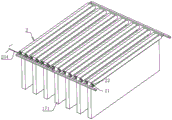
Fig. 1 is a schematic structural diagram of a portable air condensation system based on semiconductor refrigeration in an embodiment.
Fig. 2 is a cross-sectional view taken along A-A of fig. 1.
Fig. 3 is a schematic diagram for embodying the positional relationship among the sponge strip, the cooling tube and the straight rib segments in the embodiment.
Fig. 4 is a schematic diagram of an embodiment for embodying a cleaning structure.
FIG. 5 is a schematic diagram of an embodiment for embodying a first balloon, a second balloon, and an extrusion.
Reference numerals illustrate: 1. a housing; 11. a condensing channel; 12. a heat dissipation channel; 13. an air inlet; 14. an air outlet; 15. a water outlet hole; 16. a semiconductor refrigeration sheet; 17. a fin group; 171. straight rib slicing; 18. a transitional cambered surface; 2. a cleaning mechanism; 21. a cooling tube; 22. a sponge strip; 23. a slip assembly; 231. a sliding rod; 232. a cam; 233. a first reset member; 234. a pull rope; 235. a rotating member; 2351. a rotating rod; 2352. a gear set; 2353. a sprocket; 2354. a chain; 2355. a docking gear; 236. winding and unwinding a piece; 2361. winding a winding rod; 2362. a first gear; 2363. a first rack; 2364. a torsion spring; 24. a filter screen; 3. a pumping and exhausting piece; 31. a first fan; 32. a second fan; 4. a first air bag; 5. a second air bag; 6. an extrusion; 61. an extrusion plate; 611. a pushing surface; 62. and a second reset piece.
Detailed Description
The present application is described in further detail below in conjunction with figures 1-5.
The embodiment of the application discloses a portable air condensation system based on semiconductor refrigeration. Referring to fig. 1 and 2, the portable air condensation system based on semiconductor refrigeration comprises a hollow shell 1, wherein the hollow part of the shell 1 is composed of a condensation channel 11 and a heat dissipation channel 12 which are mutually communicated, the condensation channel 11 is positioned below the heat dissipation channel 12, two air inlets 13 and one air outlet 14 which are mutually communicated are formed in the end part of the shell 1, and the air inlets 13 and the air outlets 14 are both communicated with the hollow part inside the shell 1; the semiconductor refrigerating sheet 16 and the fin group 17 are also arranged in the shell 1, the fin group 17 is embedded in the shell 1, the number of the fin groups 17 is two, each side of the semiconductor refrigerating sheet 16 corresponds to one fin group 17, namely, one fin group 17 is positioned in the condensation channel 11, and the other fin group 17 is positioned in the heat dissipation channel 12.
Referring to fig. 2 and 3, each of the rib groups 17 includes a plurality of straight rib segments 171, and gaps for gas to pass through are reserved between adjacent straight rib segments 171. The bottom wall of the shell 1 near the condensation channel 11 is provided with a water outlet hole 15, for the straight rib segments 171 positioned in the condensation channel 11, the straight rib segments 171 are positioned above the water outlet hole 15, and the distance between the straight rib segments 171 and the water outlet hole 15 is larger than the distance between the straight rib segments 171 in the heat dissipation channel 12 and the inner wall of the shell 1.
Referring to fig. 2 and 3, the cleaning mechanism 2 is located in the condensation channel 11, and the cleaning mechanism 2 includes a cooling tube 21, a sponge strip 22, a sliding assembly 23, and a filter screen 24; each side of each straight rib segment 171 in the condensation channel 11 corresponds to one cooling pipe 21, each cooling pipe 21 corresponds to one sponge strip 22, the sponge strips 22 are sleeved on the periphery of the corresponding cooling pipe 21, and the cooling pipe 21 is filled with a refrigerant, and the refrigerant can be specifically cooling liquid or cold air; the filter screen 24 is fixedly welded on the inner wall of the water outlet hole 15, the filter screen 24 is positioned below the sponge strip 22, and the sliding component 23 is used for driving the cooling pipe 21 to slide in a direction away from the filter screen 24 after approaching.
Referring to fig. 2 and 4, the slip assembly 23 includes a slip lever 231, a cam 232, a first return member 233, a pulling cord 234, a rotating member 235, and a winding and unwinding member 236, and the winding and unwinding member 236 includes a winding and unwinding lever 2361, a first gear 2362, a first rack 2363, and a torsion spring 2364. Cam 232 and winding rod 2361 all rotate and connect in casing 1 lateral wall, rotate the piece 235 and be used for driving cam 232 to rotate, cam 232 perisporium has the bellying along its circumference integrated into one piece, the bellying makes cam 232 external diameter along its cam 232 circumference increase gradually, slide the pole 231 and slide and connect in casing 1 lateral wall along casing 1 direction of height, and slide pole 231 one side is equipped with the cambered surface that gives way with bellying looks butt, first return piece 233 specifically can be the spring of welding between slide pole 231 and casing 1, the flexible direction of first return piece 233 is on a parallel with the slip direction of slide pole 231, in order to be used for when the cam 232 bellying breaks away from the contact with slide pole 231, drive slide pole 231 and shift up and reset.
Referring to fig. 2, 3 and 4, the first rack 2363 is fixedly welded to the side wall of the sliding rod 231, the first rack 2363 is arranged along the length direction of the sliding rod 231, the first gear 2362 is fixedly sleeved outside the winding rod 2361, the first gear 2362 is meshed with the first rack 2363, the torsion spring 2364 is sleeved on the winding rod 2361, one end of the torsion spring 2364 is welded to the side wall of the winding rod 2361, and the other end is welded to the side wall of the shell 1; one end of the pull rope 234 is wound on the winding rod 2361, the other end of the pull rope penetrates through the shell 1 and bypasses the fixed pulley preinstalled on the shell 1, and then the pull rope is fixedly bound on the cooling pipe 21, and in the initial state of the torsion spring 2364, the cooling pipe 21 is suspended at one end of the straight rib segment 171, which is far away from the water outlet hole 15, under the action of the pull rope 234.
Referring to fig. 2 and 4, a pumping unit 3 is disposed in the housing 1, the pumping unit 3 is located at a junction between the condensation channel 11 and the heat dissipation channel 12, the pumping unit 3 specifically includes a first fan 31 and a second fan 32, the first fan 31 is located at a side of the second fan 32 away from the condensation channel 11, one air inlet 13 is located at a junction between the condensation channel 11 and the heat dissipation channel 12, and the first fan 31 is rotatably connected to an inner wall of the air inlet 13. The rotating member 235 includes two rotating rods 2351 and a gear set 2352, the gear set 2352 includes two sprockets 2353, a chain 2354 drivingly connected to the sprockets 2353, and two intermeshing gears 2355; one of the rotating rods 2351 is fixedly welded to the rotation center of the first fan 31, one of the chain wheels 2353 is fixedly sleeved outside the rotating rod 2351, the other chain wheel 2353 and one of the docking gears 2355 are coaxially and rotatably connected to the housing 1, the other docking gear 2355 is fixedly sleeved on the other rotating rod 2351, one end of the rotating rod 2351 directly connected with the docking gear 2355 is welded to the rotation center of the second fan 32, and the other end of the rotating rod 2351 is welded to the rotation center of the cam 232. The first fan 31 is externally connected with a power supply, and the suction direction of the air by the first fan 31 is opposite to the suction direction of the air by the second fan 32.
Referring to fig. 2 and 5, a transition cambered surface 18 is arranged on the inner wall of the junction of the condensation channel 11 and the heat dissipation channel 12 of the shell 1, a plurality of first air bags 4 are arranged on the transition cambered surface 18, a second air bag 5 is arranged on the side wall of the side, away from the transition cambered surface 18, of the shell 1, the second air bags 5 are communicated with all the first air bags 4, inert gas is contained in the first air bags 4 and the second air bags 5, and the bags of the first air bags 4 and the second air bags 5 are made of elastic materials.
Referring to fig. 2 and 5, an extrusion member 6 for extruding the second air bag 5 is further provided on the housing 1, the extrusion member 6 includes an extrusion plate 61 and a second restoring member 62, the extrusion plate 61 is slidably connected to the housing 1, and the second air bag 5 is located on a sliding path of the extrusion plate 61, and a side of the extrusion plate 61 facing away from the second air bag 5 is provided with a pushing surface 611 for contacting with a bottom of the sliding rod 231.
The embodiment of the application discloses a portable air condensation system based on semiconductor refrigeration's implementation principle does: the semiconductor refrigerating sheet 16 is electrically connected to a direct current power supply, the first fan 31 is started, when the first fan 31 rotates, the second fan 32 is driven to rotate by the rotating piece 235, so that wet air outside the shell 1 is sucked into the shell 1 from the two air inlets 13, wet air entering the shell 1 from the air inlet 13 far away from the first fan 31 traverses the condensation channel 11, in the process, part of the wet air is precooled into liquid water and is discharged from the water outlet hole 15, part of the wet air is changed into saturated low-temperature air, and after passing through the condensation channel 11 and the wet air at the first fan 31, the wet air passes through the heat dissipation channel 12, after heat dissipation is carried out for the heat dissipation channel 12, the mixed air becomes wet air with lower moisture content, and finally the wet air is discharged from the air outlet 14.
The foregoing are all preferred embodiments of the present application, and are not intended to limit the scope of the present application in any way, therefore: all equivalent changes in structure, shape and principle of this application should be covered in the protection scope of this application.
Claims (9)
1. The portable air condensation system based on semiconductor refrigeration comprises a shell (1), wherein a semiconductor refrigeration piece (16) and rib groups (17) positioned on two side walls of the semiconductor refrigeration piece (16) are arranged in the shell (1), the interior of the shell (1) comprises a condensation channel (11) and a heat dissipation channel (12) which are communicated with each other, the cold end of the semiconductor refrigeration piece (16) is positioned in the condensation channel (11), and the hot end of the semiconductor refrigeration piece (16) is positioned in the heat dissipation channel (12); a water outlet hole (15) is formed in the bottom wall, close to the condensation channel (11), of the shell (1); the method is characterized in that: the novel air conditioner is characterized in that an air inlet (13) and an air outlet (14) are formed in the side wall of the shell (1), a pumping and exhausting piece (3) is further arranged in the shell (1), the pumping and exhausting piece (3) is used for pumping air at the air inlet (13) to the air outlet (14) to be exhausted after passing through a condensation channel (11) and a heat dissipation channel (12) in sequence, the rib group (17) at least comprises a plurality of straight rib fragments (171), the end portions of the straight rib fragments (171) are connected to the side wall, close to a semiconductor refrigerating sheet (16), of the shell (1), and a cleaning mechanism (2) for cleaning each straight rib fragment (171) is arranged in the shell (1).
2. The semiconductor refrigeration-based portable air condensing system according to claim 1, wherein: the cleaning mechanism (2) comprises a sponge strip (22), a sliding component (23) and a filter screen (24), wherein the filter screen (24) is arranged on the inner wall of the water outlet hole (15) and is positioned below the sponge strip (22), and the sliding component (23) is used for driving the sponge strip (22) to slide towards a direction close to or far away from the filter screen (24) and is pressed on the surface of the filter screen (24) when sliding to the filter screen (24).
3. The semiconductor refrigeration-based portable air condensing system according to claim 2, wherein: the cleaning mechanism (2) further comprises a cooling pipe (21), a refrigerant is filled in the cooling pipe (21), the cooling pipe (21) and the sponge strips (22) are arranged in a one-to-one correspondence mode, the sponge strips (22) are sleeved on the periphery of the cooling pipe (21) and attached to the peripheral wall of the cooling pipe (21), and the sliding assembly (23) is used for driving the cooling pipe (21) to slide back and forth along the height direction of the straight rib fragments (171).
4. A portable air condensing system based on semiconductor refrigeration according to claim 3, characterized in that: the sliding assembly (23) comprises a sliding rod (231), a cam (232), a first resetting piece (233), a pull rope (234), a rotating piece (235) and a winding and unwinding piece (236), wherein the cam (232) is rotationally connected to the shell (1), the rotating piece (235) is used for driving the cam (232) to rotate, a protruding portion for pressing the sliding rod (231) is arranged on the side wall of the cam (232), the first resetting piece (233) is used for driving the sliding rod (231) to reset after the cam (232) releases pressing the sliding rod (231), one end of the pull rope (234) is connected to the cooling pipe (21), the other end of the pull rope is controlled by the winding and unwinding piece (236), and the winding and unwinding piece (236) is used for winding and unwinding the pull rope (234) when the sliding rod (231) slides so as to drive the cooling pipe (21) to lift through the pull rope (234).
5. The semiconductor refrigeration based portable air condensing system of claim 4, wherein: the winding and unwinding piece (236) comprises a winding rod (2361) rotatably connected to the shell (1), a first gear (2362) sleeved on the winding rod (2361), and a first rack (2363) meshed with the first gear (2362), wherein the first rack (2363) is arranged on the side wall of the sliding rod (231) along the length direction of the sliding rod (231), and one end, far away from the cooling pipe (21), of the pull rope (234) is wound on the winding rod (2361).
6. The semiconductor refrigeration based portable air condensing system of claim 4, wherein: the suction and exhaust piece (3) comprises a first fan (31), the rotating piece (235) comprises two rotating rods (2351) and a gear set (2352), the two rotating rods (2351) are all rotationally connected to the shell (1), one rotating rod (2351) is connected to the rotating center of the first fan (31), the other rotating rod (2351) is connected to the rotating center of the cam (232), and the gear set (2352) is used for driving the rotating rod (2351) connected with the cam (232) to rotate when the rotating rod (2351) connected with the first fan (31) rotates.
7. The semiconductor refrigeration based portable air condensing system of claim 6, wherein: the pumping and exhausting piece (3) further comprises a second fan (32), the second fan (32) is located at the junction of the condensing channel (11) and the radiating channel (12), the second fan (32) is located at one side, away from the condensing channel (11), of the first fan (31), the rotating rod (2351) connected with the rotating center of the cam (232) is connected with the rotating center of the second fan (32), and the wind directions of the second fan (32) and the first fan (31) are opposite.
8. The semiconductor refrigeration based portable air condensing system of claim 4, wherein: the novel air conditioner is characterized in that a transition cambered surface (18) is arranged on the side wall of the junction of the condensation channel (11) and the heat dissipation channel (12) inside the shell (1), a plurality of first air bags (4) are arranged on the transition cambered surface (18), a second air bag (5) is arranged on the side wall of one side of the shell (1) away from the transition cambered surface (18), the second air bags (5) are communicated with all the first air bags (4), gas is filled in the second air bags (5), and an extrusion piece (6) for extruding the second air bags (5) is further arranged on the shell (1).
9. The semiconductor refrigeration based portable air condensing system of claim 8, wherein: the extrusion piece (6) comprises an extrusion plate (61) and a second reset piece (62), the extrusion plate (61) is connected to the shell (1) in a sliding mode, the second air bag (5) is located on the sliding path of the extrusion plate (61), and one side, away from the second air bag (5), of the extrusion plate (61) is provided with a pushing surface (611) used for being in contact with the bottom of the sliding rod (231).
Priority Applications (1)
| Application Number | Priority Date | Filing Date | Title |
|---|---|---|---|
| CN202320696011.2U CN219347392U (en) | 2023-03-31 | 2023-03-31 | Portable air condensation system based on semiconductor refrigeration |
Applications Claiming Priority (1)
| Application Number | Priority Date | Filing Date | Title |
|---|---|---|---|
| CN202320696011.2U CN219347392U (en) | 2023-03-31 | 2023-03-31 | Portable air condensation system based on semiconductor refrigeration |
Publications (1)
| Publication Number | Publication Date |
|---|---|
| CN219347392U true CN219347392U (en) | 2023-07-14 |
Family
ID=87099173
Family Applications (1)
| Application Number | Title | Priority Date | Filing Date |
|---|---|---|---|
| CN202320696011.2U Active CN219347392U (en) | 2023-03-31 | 2023-03-31 | Portable air condensation system based on semiconductor refrigeration |
Country Status (1)
| Country | Link |
|---|---|
| CN (1) | CN219347392U (en) |
-
2023
- 2023-03-31 CN CN202320696011.2U patent/CN219347392U/en active Active
Similar Documents
| Publication | Publication Date | Title |
|---|---|---|
| CN114857806B (en) | Multifunctional complementary air source heat pump system with defrosting function | |
| CN109297173B (en) | Air conditioner refrigeration plate anti-freezing device with automatic extrusion and drainage functions | |
| CN116791935B (en) | Heat-insulating movable board house | |
| CN219347392U (en) | Portable air condensation system based on semiconductor refrigeration | |
| CN116182580A (en) | Portable air condensation system based on semiconductor refrigeration and working method thereof | |
| CN117968244A (en) | Condensate water recovery device of central air conditioner | |
| CN113834020A (en) | LED lamp for outdoor lighting | |
| CN116292113B (en) | Wind driven generator | |
| CN109268053A (en) | A kind of low-carbon environment-friendly tunnel structure | |
| CN112161416A (en) | Heat pump heat exchanger and heat pump using same | |
| CN115059973B (en) | Ground source heat pump energy-saving air conditioner applying fuzzy mathematics | |
| CN115489310A (en) | LED automobile instrument with heat dissipation effect | |
| CN115767966A (en) | Communication base station with remote early warning and intelligent three-prevention functions | |
| CN211372615U (en) | Portable mobile air conditioner | |
| CN2377474Y (en) | Condensed water treating device for split air conditioner | |
| CN112432357A (en) | Air conditioner capable of preventing water from dripping by utilizing suction force adsorption | |
| CN221684902U (en) | Circulating air cooling device of frost prevention refrigeration house | |
| CN114217109B (en) | Moistureproof ammeter with network meter reading function | |
| CN117154287B (en) | Low-noise energy storage cabinet | |
| CN220556803U (en) | Service equipment for wireless communication | |
| CN116105400B (en) | Valve assembly for air source heat pump and heat pump system | |
| CN220567473U (en) | Line type wind gap | |
| CN214468980U (en) | Air conditioner outdoor unit and air conditioning unit | |
| CN217763993U (en) | Industrial electrical cabinet air conditioner drainage evaporator | |
| CN115046356B (en) | Tail gas absorption device for asphalt modifier production and working method thereof |
Legal Events
| Date | Code | Title | Description |
|---|---|---|---|
| GR01 | Patent grant | ||
| GR01 | Patent grant |