CN219314449U - Automatic lifting device for die trolley - Google Patents
Automatic lifting device for die trolley Download PDFInfo
- Publication number
- CN219314449U CN219314449U CN202320791776.4U CN202320791776U CN219314449U CN 219314449 U CN219314449 U CN 219314449U CN 202320791776 U CN202320791776 U CN 202320791776U CN 219314449 U CN219314449 U CN 219314449U
- Authority
- CN
- China
- Prior art keywords
- lifting device
- automatic lifting
- rods
- rod
- frame
- Prior art date
- Legal status (The legal status is an assumption and is not a legal conclusion. Google has not performed a legal analysis and makes no representation as to the accuracy of the status listed.)
- Active
Links
Images

Abstract
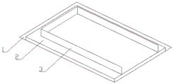
The utility model provides an automatic lifting device for a die trolley, which comprises a pit and an automatic lifting device, wherein the pit is arranged on the ground, the automatic lifting device is arranged in the pit, a flat plate is arranged at the top of the automatic lifting device, the flat plate is flush with the ground when the automatic lifting device does not work, a positioning baffle is arranged at the top of the flat plate, and the positioning baffle is continuously arranged on three sides. The device is arranged on one side of the front end of the production line, the die trolley is conveniently pushed onto the top plate of the lifting device, and the die on the trolley is always positioned on the same horizontal line with the table top of the production line by adjusting the height of the trolley, so that a worker can conveniently move the die to the table top of the production line.
Description
Technical Field
The utility model relates to the technical field of lifting devices, in particular to an automatic lifting device for a die trolley.
Background
In the production process of the foam glass, the moulds are required to be placed on a production line at intervals, the mixed raw materials of the foam glass are quantitatively put into the moulds, and the moulds are transported into a heating kiln on the production line for high-temperature treatment, so that the foam glass is obtained. At present, on a foam glass production line, the placement of the mould generally adopts the manual work, firstly stacks and transports a plurality of moulds to the front end of the production line through the trolley, then manually places the moulds on the production line, the raw materials can be automatically put or manually put in, but the mould itself is made of thickened steel plates, is relatively heavy, and an operator is in a state of bending down to take the mould for a long time and vertically places the mould, so that the mould is very tired.
Disclosure of Invention
The utility model provides an automatic lifting device for a die trolley, which is characterized in that the die trolley is pushed to the top of the lifting device, and the die on the trolley and the table top of a production line are always positioned on the same horizontal line by adjusting the height of the trolley, so that the die can be conveniently moved to the table top of the production line.
The utility model adopts the technical scheme that:
the utility model provides an automatic lifting device for mould dolly, includes the pit of seting up on ground, sets up the automatic lifting device in the pit, automatic lifting device's top is provided with the flat board, just flat board is with ground parallel and level when automatic lifting device does not work, flat board's top is provided with positioning baffle, positioning baffle is trilateral continuous arrangement.
Preferably, the automatic lifting device comprises a bottom frame and a top frame which are sequentially arranged from bottom to top, the bottom frame comprises a bottom frame, two hydraulic cylinders are arranged on the bottom frame at intervals and vertically, the ends of telescopic rods of the two hydraulic cylinders are fixed at the bottom of the top frame, and the flat plate is arranged at the top of the top frame.
Preferably, positioning rods are arranged around the bottom frame, hollow rods are arranged at positions, corresponding to the positioning rods, of the bottom of the top frame, and the hollow rods are sleeved outside the positioning rods.
Preferably, a first reinforcing rod is arranged between the hollow rods, the first reinforcing rod is positioned at the lower parts of two adjacent hollow rods, a second reinforcing rod and a third reinforcing rod are also arranged between the hollow rods in a crossing manner, and the second reinforcing rod and the third reinforcing rod are positioned above the first reinforcing rod.
Preferably, the upper parts of the two hydraulic cylinders are respectively sleeved with a clamp, a connecting rod is arranged between the clamps, the connecting rod is fixed through two groups of supporting rods, each group of supporting rods is splayed and arranged on the front side and the rear side of the connecting rod, one end of each supporting rod is arranged on the connecting rod, and the other end of each supporting rod is arranged on the bottom frame.
Compared with the prior art, the utility model has the beneficial effects that: this automatic lifting device for mould dolly sets up in production line front end one side, and its top flat board of automatic lifting device during non-working is dull and stereotyped with ground parallel and level, conveniently pushes away the mould dolly to on the elevating gear top flat board, and automatic lifting device starts, and the flat board is along with rising, and then makes the dolly rise in height, makes mould on the dolly always be in same water flat line with the mesa of production line, and operating personnel need not the operation of bending over, can conveniently move the mould to the production line mesa.
Drawings
Fig. 1 is a schematic structural view of the present utility model.
Fig. 2 is a schematic view of an operating state of the automatic lifting device.
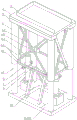
Fig. 3 is an exploded view of the automatic lifting device.
In the figure: 1. pit; 2. a flat plate; 3. positioning a baffle; 4. a chassis; 5. a top frame; 6. a hollow rod; 7. a hydraulic cylinder; 8. a clamp; 9. a connecting rod; 10. a support rod; 41. a bottom frame; 42. a positioning rod; 61. a first reinforcing rod; 62. a second reinforcing rod; 63. a third reinforcing rod; 64. a rectangular plate; 65. and (5) connecting a plate.
Detailed Description
In order to more clearly illustrate the embodiments of the present utility model or the technical solutions in the prior art, the drawings used in the description of the embodiments or the prior art will be briefly described below.
As shown in fig. 1 and 2, the automatic lifting device for the die trolley is arranged at one side of the front end of a production line, and when the lifting device does not work, the top flat plate is flush with the ground, so that the die trolley is conveniently pushed onto the top flat plate of the lifting device, the automatic lifting device is started, and the flat plate rises along with the lifting, so that the height of the trolley rises, the die on the trolley and the table top of the production line are always on the same horizontal line, and the die is conveniently moved to the table top of the production line.
Specifically, automatic lifting device for mould dolly, including seting up pit 1 on ground, setting up the automatic lifting device in the pit, automatic lifting device's top is provided with dull and stereotyped 2, just dull and stereotyped 2 is with ground parallel and level when automatic lifting device does not work, the top of dull and stereotyped 2 is provided with positioning baffle 3, positioning baffle 3 is trilateral continuous arrangement. The mould dolly is pushed in from dull and stereotyped open-ended one side, utilizes positioning baffle to inject mould dolly entering and placement position, avoids the dolly wheel to be close to dull and stereotyped outer edge, off tracking removal.
In this embodiment, automatic lifting device includes chassis 4, roof-rack 5 that set gradually from bottom to top, chassis 4 includes bottom frame 41, and this bottom frame is the rectangular frame that forms by the welding of diaphragm longitudinal plate, and the direct pit bottom that places, interval and vertical being provided with two pneumatic cylinders 7 on the bottom frame 41, the telescopic rod tip of two pneumatic cylinders 7 is fixed in the bottom of roof-rack 5, dull and stereotyped 2 sets up the top at roof-rack 5. The hydraulic cylinder is started, the telescopic rod stretches out to push the top frame to ascend, and the flat plate ascends along with the ascending to drive the die trolley above the flat plate to ascend. In fig. 1 and 2, a fixed block is arranged on the bottom frame 41, and the hydraulic cylinder 7 is arranged on the fixed block through a tail flange and a matched locking bolt, and the lifting height is about 1 m 2, so that the end part of the telescopic rod can be fixed at the bottom of the top frame under the non-working condition by utilizing the fixed block to lift the height of the hydraulic cylinder. The top frame structure is not limited, and the end part of the telescopic rod can be conveniently fixed with the flat plate.
In addition, considering that the vertical support of the top frame is realized by only two hydraulic telescopic rods, in the case of long-term offset of the mold trolley, there may be a phenomenon of tilting of the top frame, and thus, the positioning rods 42 are provided around the bottom frame 41, the hollow rods 6 are provided at positions corresponding to the positioning rods 42 at the bottom of the top frame 5, and the hollow rods 6 are sleeved outside the positioning rods 42. The movable position of the telescopic rod of the hydraulic cylinder is limited by utilizing the mutual matching of the positioning rod and the hollow rod, and the bearing capacity of the telescopic rod of the hydraulic cylinder is shared at the same time, so that the inclination of the hydraulic cylinder under the condition of uneven stress is avoided, and the roof rack is inclined.
In order to further ensure the stability of each hollow rod, a first reinforcing rod 61 is arranged between the hollow rods 6, the first reinforcing rod 61 is positioned at the lower parts of two adjacent hollow rods, a second reinforcing rod 62 and a third reinforcing rod 63 are also arranged between the hollow rods in a crossing manner, and the second reinforcing rod 62 and the third reinforcing rod 63 are positioned above the first reinforcing rod 61. In this embodiment, the fixing manner of the first reinforcing rod, the second reinforcing rod and the third reinforcing rod is that rectangular plates 64 are welded on the upper part and the lower part of the hollow rod respectively, two ends of the first reinforcing rod 61 are welded on the lower rectangular plates 64 of two adjacent hollow rods respectively, one end of the second reinforcing rod 62 and one end of the third reinforcing rod 63 are welded on the upper reinforcing plate of the hollow rod, the other end of the second reinforcing rod 62 and the other end of the third reinforcing rod are welded on the lower reinforcing plate of the adjacent hollow rod, the second reinforcing rod 62 and the third reinforcing rod 63 are arranged in a crossed manner, as shown in fig. 1 and 2, the arrangement manner can be that the second reinforcing rod and the third reinforcing rod are welded on the front side and the rear side of the rectangular plates respectively, the middle parts of the second reinforcing rod and the third reinforcing rod are welded and fixed on the front side and the rear side of the connecting plate 65 respectively, and the third reinforcing rod can also be discontinuously and crossly arranged on two sides of the second reinforcing rod.
In addition, in order to further enhance the stability of the hydraulic cylinders, the upper parts of the two hydraulic cylinders 7 are respectively sleeved with a clamp 8, a connecting rod 9 is arranged between the clamps 8, the connecting rod 9 is fixed through two groups of supporting rods 10, each group of supporting rods 10 is splayed and arranged on the front side and the rear side of the connecting rod, one end of each supporting rod 10 is arranged on the connecting rod 9, and the other end is arranged on the bottom frame 41. Through the cooperation of connecting rod and bracing piece, realize the steadiness on pneumatic cylinder upper portion.
The application process of the utility model is as follows: when the automatic lifting device does not work, as shown in figure 1, the top flat plate of the automatic lifting device is level with the ground, so that the pushing-in of the mould trolley is facilitated; when the die trolley is pushed onto the flat plate, the hydraulic cylinder is started, the telescopic rod of the hydraulic cylinder extends upwards, as shown in fig. 2, the top frame is pushed to rise, the height of the trolley is further increased, the die on the trolley is always on the same horizontal line with the table top of the production line, and an operator does not need to bend to operate, so that the die can be conveniently moved to the table top of the production line.
Claims (5)
1. An automatic lifting device for a die trolley is characterized in that: including seting up pit, the automatic lifting device of setting in the pit on ground, automatic lifting device's top is provided with the flat board, just the flat board is with ground parallel and level when automatic lifting device does not work, the top of flat board is provided with positioning baffle, positioning baffle is trilateral continuous arrangement.
2. The automatic lifting device for a mold trolley according to claim 1, wherein: the automatic lifting device comprises a bottom frame and a top frame which are sequentially arranged from bottom to top, wherein the bottom frame comprises a bottom frame, two hydraulic cylinders are vertically arranged on the bottom frame at intervals, the ends of telescopic rod of the two hydraulic cylinders are fixed at the bottom of the top frame, and the flat plate is arranged at the top of the top frame.
3. The automatic lifting device for a mold trolley according to claim 2, wherein: the locating rods are arranged around the bottom frame, hollow rods are arranged at the positions, corresponding to the locating rods, of the bottom of the top frame, and the hollow rods are sleeved outside the locating rods.
4. An automatic lifting device for a mold trolley according to claim 3, wherein: the hollow rods are provided with first reinforcing rods, the first reinforcing rods are located at the lower parts of two adjacent hollow rods, the hollow rods are also provided with second reinforcing rods and third reinforcing rods in a crossing mode, and the second reinforcing rods and the third reinforcing rods are located above the first reinforcing rods.
5. The automatic lifting device for a mold trolley according to claim 2, wherein: the upper parts of the two hydraulic cylinders are respectively sleeved with a clamp, a connecting rod is arranged between the clamps, the connecting rods are fixed through two groups of supporting rods, each group of supporting rods are arranged on the front side and the rear side of the connecting rod in a splayed mode, one end of each supporting rod is arranged on the connecting rod, and the other end of each supporting rod is arranged on the bottom frame.
Priority Applications (1)
| Application Number | Priority Date | Filing Date | Title |
|---|---|---|---|
| CN202320791776.4U CN219314449U (en) | 2023-04-12 | 2023-04-12 | Automatic lifting device for die trolley |
Applications Claiming Priority (1)
| Application Number | Priority Date | Filing Date | Title |
|---|---|---|---|
| CN202320791776.4U CN219314449U (en) | 2023-04-12 | 2023-04-12 | Automatic lifting device for die trolley |
Publications (1)
| Publication Number | Publication Date |
|---|---|
| CN219314449U true CN219314449U (en) | 2023-07-07 |
Family
ID=87033797
Family Applications (1)
| Application Number | Title | Priority Date | Filing Date |
|---|---|---|---|
| CN202320791776.4U Active CN219314449U (en) | 2023-04-12 | 2023-04-12 | Automatic lifting device for die trolley |
Country Status (1)
| Country | Link |
|---|---|
| CN (1) | CN219314449U (en) |
-
2023
- 2023-04-12 CN CN202320791776.4U patent/CN219314449U/en active Active
Similar Documents
| Publication | Publication Date | Title |
|---|---|---|
| CN206484700U (en) | T beam hydraulic ejections mechanism | |
| CN219314449U (en) | Automatic lifting device for die trolley | |
| CN212577228U (en) | Support frame for plate bending machine | |
| CN210969356U (en) | Turnover machine capable of automatically replacing bottom plate | |
| CN207610630U (en) | A kind of gunnery training target drone of automatic lifting and translation | |
| CN113647660A (en) | Tobacco loading and unloading device for tobacco curing room | |
| CN213865193U (en) | Lifting device for small and medium-sized equipment | |
| CN211765681U (en) | Discharging frame for building construction | |
| CN217436931U (en) | Lifting platform for stacking plates | |
| CN113000924A (en) | Pipe fitting processing auxiliary device | |
| CN216059158U (en) | Tobacco loading and unloading device for tobacco curing room | |
| CN220536724U (en) | Unloading and transferring system suitable for copper pillar sawing machine | |
| CN111590140A (en) | Liftable steel sheet bracket | |
| CN206872065U (en) | A kind of full-automatic fortune brick device | |
| CN217417225U (en) | Side discharging conveying mechanism for steel grating welding machine | |
| CN219172468U (en) | Fitment is with material handling device convenient to it is fixed | |
| CN214358752U (en) | Push-pull device of condenser | |
| CN216188577U (en) | Simple and easy feed structure of flat pipe | |
| CN217497576U (en) | A portable transfer device for bean vermicelli drying process | |
| CN216198149U (en) | Utility tunnel construction trolley | |
| CN215794541U (en) | Filling and lifting mechanism for composite material | |
| CN218464974U (en) | Automatic device that piles up of transport battery tray dolly | |
| CN214867605U (en) | Pipe fitting processing auxiliary device | |
| CN210476025U (en) | Semitrailer boxboard welding supporting platform | |
| CN213171344U (en) | Multifunctional material transfer trolley |
Legal Events
| Date | Code | Title | Description |
|---|---|---|---|
| GR01 | Patent grant | ||
| GR01 | Patent grant |