CN219310736U - Workpiece clamping device for milling machine - Google Patents
Workpiece clamping device for milling machine Download PDFInfo
- Publication number
- CN219310736U CN219310736U CN202320558528.5U CN202320558528U CN219310736U CN 219310736 U CN219310736 U CN 219310736U CN 202320558528 U CN202320558528 U CN 202320558528U CN 219310736 U CN219310736 U CN 219310736U
- Authority
- CN
- China
- Prior art keywords
- clamping device
- clamping
- milling machine
- workpiece
- rotary driving
- Prior art date
- Legal status (The legal status is an assumption and is not a legal conclusion. Google has not performed a legal analysis and makes no representation as to the accuracy of the status listed.)
- Active
Links
Images
Classifications
-
- Y—GENERAL TAGGING OF NEW TECHNOLOGICAL DEVELOPMENTS; GENERAL TAGGING OF CROSS-SECTIONAL TECHNOLOGIES SPANNING OVER SEVERAL SECTIONS OF THE IPC; TECHNICAL SUBJECTS COVERED BY FORMER USPC CROSS-REFERENCE ART COLLECTIONS [XRACs] AND DIGESTS
- Y02—TECHNOLOGIES OR APPLICATIONS FOR MITIGATION OR ADAPTATION AGAINST CLIMATE CHANGE
- Y02P—CLIMATE CHANGE MITIGATION TECHNOLOGIES IN THE PRODUCTION OR PROCESSING OF GOODS
- Y02P70/00—Climate change mitigation technologies in the production process for final industrial or consumer products
- Y02P70/10—Greenhouse gas [GHG] capture, material saving, heat recovery or other energy efficient measures, e.g. motor control, characterised by manufacturing processes, e.g. for rolling metal or metal working
Landscapes
- Jigs For Machine Tools (AREA)
- Milling Processes (AREA)
Abstract
The utility model discloses a workpiece clamping device for a milling machine, which comprises a clamping device main body, a bidirectional screw rod, clamping heads and movable sleeves, wherein the bidirectional screw rod is arranged in the clamping device main body, driving blocks are sleeved at two ends of the bidirectional screw rod, a first rotary driving mechanism is fixed on one side of the clamping device main body, the output end of the first rotary driving mechanism is connected with the bidirectional screw rod, fixing rods are fixed at the tops of the driving blocks, the movable sleeves are sleeved on the fixing rods, and clamping heads are arranged on one sides of the movable sleeves. According to the clamping device, the clamping device body, the bidirectional screw rod, the driving block, the first rotary driving mechanism, the fixing rod and the clamping head are arranged, the first rotary driving mechanism drives the bidirectional screw rod to rotate, so that the driving blocks are close to each other, a workpiece is clamped and fixed by the clamping head, the structure is simple, the operation is convenient, the workpiece can be clamped by only one group of first rotary driving mechanisms, and the energy conservation and the emission reduction are facilitated.
Description
Technical Field
The utility model relates to the technical field of workpiece clamping devices, in particular to a workpiece clamping device for a milling machine.
Background
The milling machine is a machine tool for machining the surface of a workpiece by using a milling cutter, and in order to facilitate the machining of the workpiece by using the milling cutter of the milling machine, a clamping device is required to be installed on the milling machine and used for preventing the workpiece from generating displacement or vibration in the machining process, and the clamping effect of the clamping device directly influences the machining quality and the production efficiency of the workpiece.
When the clamping device works, the clamping heads are driven by pneumatic equipment to approach each other so as to clamp the workpiece, and the structure has higher manufacturing cost and is not beneficial to energy conservation and emission reduction; 2. the clamping head of the clamping device is usually fixed, so that the clamping device is not convenient to disassemble and replace, and the height position of the clamped workpiece is not easy to adjust; 3. the clamping device generally only has the function of clamping the workpiece, and the position of the workpiece needs to be adjusted when the workpiece is actually machined so as to facilitate better milling machining.
Disclosure of Invention
The utility model aims to provide a workpiece clamping device for a milling machine, which aims to solve the problems in the background technology.
In order to achieve the above purpose, the present utility model provides the following technical solutions: the utility model provides a work piece clamping device that milling machine was used, includes clamping device main part, two-way lead screw, chuck and movable sleeve, the inside of clamping device main part is provided with two-way lead screw, just the both ends of two-way lead screw all overlap and are equipped with the drive block, one side of clamping device main part is fixed with first rotary driving mechanism, just the output and the two-way lead screw of first rotary driving mechanism are connected, the top of drive block all is fixed with the dead lever, just all overlap on the dead lever and be equipped with the movable sleeve, one side of movable sleeve all is provided with the chuck.
Preferably, a base is arranged below the clamping device main body, a second rotary driving mechanism is arranged in the base, a turntable is arranged at the output end of the second rotary driving mechanism through a roller, and the top end of the turntable is connected with the bottom of the clamping device main body.
Preferably, a guide rod is arranged at the bottom end in the clamping device main body, and the bottom of the driving block is in sliding sleeve joint with the guide rod through a guide sleeve.
Preferably, screw holes are uniformly formed in one side of the fixing rod, and one side of the movable sleeve is fixedly connected with the screw holes through fasteners.
Preferably, clamping plates are arranged in the clamping heads, and the clamping plates and the clamping heads are in circular arc structures.
Preferably, a buffer groove is uniformly formed in one side of the inside of the chuck, a pressure receiving piece is uniformly arranged in the buffer groove through a buffer spring, and one end of the pressure receiving piece is connected with the clamping plate.
Preferably, the top surface of base has seted up the ring channel, the both sides of carousel bottom all are provided with the slider with ring channel assorted.
Compared with the prior art, the utility model has the beneficial effects that:
1. the workpiece clamping device for the milling machine is characterized in that the clamping device body, the bidirectional screw rod, the driving block, the first rotary driving mechanism, the fixing rod and the clamping head are arranged, the first rotary driving mechanism drives the bidirectional screw rod to rotate, the driving block is close to each other, the workpiece is clamped and fixed by the clamping head, the structure is simple, the operation is convenient, the workpiece can be clamped only by the first rotary driving mechanism, and the energy conservation and the emission reduction are facilitated.
2. The workpiece clamping device for the milling machine is characterized in that one side of the clamping head is provided with the movable sleeve, the movable sleeve is sleeved on the fixed rod, screw holes are uniformly distributed on the fixed rod, the movable sleeve is fixed with the screw holes at different positions through the fasteners, the height position of the clamping head can be adjusted, meanwhile, the movable sleeve can be separated from the fixed rod, and the clamping heads with different specifications can be replaced to adapt to clamping of different workpieces.
3. The workpiece clamping device for the milling machine is characterized in that the base, the second rotary driving mechanism, the turntable, the annular groove and the sliding block are arranged, the second rotary driving mechanism can drive the turntable to rotate through the rolling shaft, so that the clamping device main body rotates, the position of a workpiece is adjusted, a milling cutter on the milling machine can process different positions of the workpiece, and the sliding block slides in the annular groove when the turntable rotates, so that the stability of the milling machine is improved.
Drawings
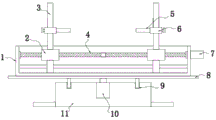
FIG. 1 is a schematic cross-sectional elevation view of the present utility model;
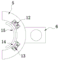
FIG. 2 is a schematic top view of a chuck according to the present utility model;
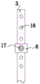
FIG. 3 is a schematic side view of a fixing rod according to the present utility model;
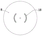
fig. 4 is a schematic view showing a bottom view of the turntable according to the present utility model.
In the figure: 1. a clamping device body; 2. a driving block; 3. a fixed rod; 4. a two-way screw rod; 5. a chuck; 6. a movable sleeve; 7. a first rotary drive mechanism; 8. a turntable; 9. an annular groove; 10. a second rotary drive mechanism; 11. a base; 12. a buffer tank; 13. a buffer spring; 14. a pressure receiving member; 15. a clamping plate; 16. a screw hole; 17. a fastener; 18. a sliding block.
Detailed Description
The technical solutions in the embodiments of the present utility model will be clearly and completely described below with reference to the accompanying drawings in the embodiments of the present utility model. All other embodiments, which can be made by those skilled in the art based on the embodiments of the utility model without making any inventive effort, are intended to be within the scope of the utility model.
Referring to fig. 1-4, an embodiment of the present utility model is provided: the workpiece clamping device for the milling machine comprises a clamping device main body 1, a bidirectional screw rod 4, a chuck 5 and a movable sleeve 6, wherein the bidirectional screw rod 4 is arranged in the clamping device main body 1, driving blocks 2 are sleeved at two ends of the bidirectional screw rod 4, a first rotary driving mechanism 7 is fixed on one side of the clamping device main body 1, the output end of the first rotary driving mechanism 7 is connected with the bidirectional screw rod 4, and the first rotary driving mechanism 7 drives the bidirectional screw rod 4 to rotate so that the driving blocks 2 are close to each other;
the top of the driving block 2 is fixed with a fixed rod 3, the fixed rod 3 is sleeved with a movable sleeve 6, and one side of the movable sleeve 6 is provided with a chuck 5;
the driving block 2 drives the clamping heads 5 to mutually approach, clamping plates 15 are arranged in the clamping heads 5, the clamping plates 15 and the clamping heads 5 are of circular arc structures, workpieces are clamped and fixed by the aid of the clamping plates 15 in the clamping heads 5, and the clamping head is simple in structure and convenient to operate, can clamp the workpieces only through a group of first rotary driving mechanisms 7, and is beneficial to energy conservation and emission reduction;
a buffer groove 12 is uniformly formed in one side of the inside of the chuck 5, a pressure receiving piece 14 is uniformly arranged in the buffer groove 12 through a buffer spring 13, and one end of the pressure receiving piece 14 is connected with a clamping plate 15;
when the clamping plate 15 contacts with a workpiece, the pressure receiving piece 14 is caused to compress the buffer spring 13 in the buffer groove 12, so that the compression force is dispersed, and the workpiece is prevented from being pressed;
the bottom end in the clamping device main body 1 is provided with a guide rod, the bottom of the driving block 2 is in sliding sleeve joint with the guide rod through a guide sleeve, and the driving block 2 is guided and limited;
the movable sleeve 6 is fixed with screw holes 16 at different positions through fasteners 17, the height position of the chuck 5 can be adjusted, and meanwhile, the movable sleeve 6 can be separated from the fixed rod 3, so that the chucks 5 with different specifications can be replaced to adapt to clamping of different workpieces;
a base 11 is arranged below the clamping device main body 1, a second rotary driving mechanism 10 is arranged in the base 11, a turntable 8 is arranged at the output end of the second rotary driving mechanism 10 through a roller, and the top end of the turntable 8 is connected with the bottom of the clamping device main body 1;
the base 11 is fixedly installed with the milling machine, the second rotary driving mechanism 10 can drive the turntable 8 to rotate through the rolling shaft, so that the clamping device main body 1 rotates, the position of a workpiece is further adjusted, and the milling cutter on the milling machine can process different positions of the workpiece;
the top surface of the base 11 is provided with an annular groove 9, two sides of the bottom of the turntable 8 are provided with sliding blocks 18 matched with the annular groove 9, and when the turntable 8 rotates, the sliding blocks 18 slide in the annular groove 9, so that the stability during rotation is improved;
the specific model specifications of the first rotary driving mechanism 7 and the second rotary driving mechanism 10 need to be determined according to the model selection calculation of the specification parameters and the like of the device, and the model selection calculation method is the prior art, so detailed description is omitted.
Working principle: when the embodiment of the application is used, the base 11 and the milling machine are fixedly installed, the first rotary driving mechanism 7 drives the bidirectional screw rod 4 to rotate, so that the driving blocks 2 are close to each other, the workpiece is clamped and fixed by the clamping plates 15 in the clamping heads 5, the structure is simple, the operation is convenient, the workpiece can be clamped by only one group of the first rotary driving mechanisms 7, the energy conservation and emission reduction are facilitated, the compression springs 13 are compressed in the buffer grooves 12 by the compression members 14 when the clamping plates 15 are contacted with the workpiece, the compression force is dispersed, the indentation on the workpiece is prevented, the movable sleeve 6 is arranged on one side of the clamping heads 5, the movable sleeve 6 is sleeved on the fixed rod 3, evenly distributed screw 16 on the dead lever 3, the screw 16 through fastener 17 and different positions on the movable sleeve 6 is fixed, but the high position of adjustable chuck 5 also can separate movable sleeve 6 and dead lever 3 simultaneously, and then change chuck 5 of different specifications, in order to adapt to different work pieces and press from both sides tightly, in addition, second rotary driving mechanism 10 accessible roller bearing drives carousel 8 and rotates, make clamping device main part 1 rotate, and then adjust the position of work piece, make milling cutter on the milling machine can process the different positions of work piece, slider 18 slides in ring channel 9 when carousel 8 is rotatory, stability when improving the rotation.
Claims (7)
1. The utility model provides a work piece clamping device that milling machine was used, its characterized in that, including clamping device main part (1), two-way lead screw (4), chuck (5) and movable sleeve (6), the inside of clamping device main part (1) is provided with two-way lead screw (4), just the both ends of two-way lead screw (4) all overlap and are equipped with drive block (2), one side of clamping device main part (1) is fixed with first rotary driving mechanism (7), just the output of first rotary driving mechanism (7) is connected with two-way lead screw (4), the top of drive block (2) all is fixed with dead lever (3), just all overlap on dead lever (3) and be equipped with movable sleeve (6), one side of movable sleeve (6) all is provided with chuck (5).
2. A workpiece clamping device for a milling machine as claimed in claim 1, wherein: the clamping device is characterized in that a base (11) is arranged below the clamping device body (1), a second rotary driving mechanism (10) is arranged inside the base (11), a turntable (8) is arranged at the output end of the second rotary driving mechanism (10) through a roller, and the top end of the turntable (8) is connected with the bottom of the clamping device body (1).
3. A workpiece clamping device for a milling machine as claimed in claim 1, wherein: the bottom in clamping device main part (1) is provided with the guide bar, the bottom of drive piece (2) is cup jointed with the guide bar through the uide bushing slides.
4. A workpiece clamping device for a milling machine as claimed in claim 1, wherein: screw holes (16) are uniformly formed in one side of the fixed rod (3), and one side of the movable sleeve (6) is fixedly connected with the screw holes (16) through fasteners (17).
5. A workpiece clamping device for a milling machine as claimed in claim 1, wherein: the clamping plates (15) are arranged in the clamping heads (5), and the clamping plates (15) and the clamping heads (5) are of circular arc structures.
6. A workpiece clamping device for a milling machine as defined in claim 5, wherein: buffer grooves (12) are uniformly formed in one side of the inside of the clamping head (5), pressure receiving pieces (14) are uniformly arranged in the buffer grooves (12) through buffer springs (13), and one ends of the pressure receiving pieces (14) are connected with clamping plates (15).
7. A workpiece clamping device for a milling machine as claimed in claim 2, wherein: an annular groove (9) is formed in the top surface of the base (11), and sliding blocks (18) matched with the annular groove (9) are arranged on two sides of the bottom of the rotary disc (8).
Priority Applications (1)
| Application Number | Priority Date | Filing Date | Title |
|---|---|---|---|
| CN202320558528.5U CN219310736U (en) | 2023-03-21 | 2023-03-21 | Workpiece clamping device for milling machine |
Applications Claiming Priority (1)
| Application Number | Priority Date | Filing Date | Title |
|---|---|---|---|
| CN202320558528.5U CN219310736U (en) | 2023-03-21 | 2023-03-21 | Workpiece clamping device for milling machine |
Publications (1)
| Publication Number | Publication Date |
|---|---|
| CN219310736U true CN219310736U (en) | 2023-07-07 |
Family
ID=87028940
Family Applications (1)
| Application Number | Title | Priority Date | Filing Date |
|---|---|---|---|
| CN202320558528.5U Active CN219310736U (en) | 2023-03-21 | 2023-03-21 | Workpiece clamping device for milling machine |
Country Status (1)
| Country | Link |
|---|---|
| CN (1) | CN219310736U (en) |
-
2023
- 2023-03-21 CN CN202320558528.5U patent/CN219310736U/en active Active
Similar Documents
| Publication | Publication Date | Title |
|---|---|---|
| CN103465074B (en) | Splined hub boring mesopore air-actuated jaw | |
| CN113001216A (en) | Manual combination clamping device | |
| CN211639138U (en) | Clamp for drilling center hole of square workpiece | |
| CN219310736U (en) | Workpiece clamping device for milling machine | |
| CN211249217U (en) | Fixing clamp for milling machine | |
| CN112318281A (en) | Valve seat and valve core spherical sealing surface grinding device | |
| CN201744870U (en) | Special clamp for milling groove by adjustable spanner | |
| CN202742076U (en) | Broaching clamp for forming sleeve key groove | |
| CN216881778U (en) | Two-jaw pneumatic pressing plate type chuck | |
| CN214518983U (en) | Manual combination clamping device | |
| CN215547508U (en) | Valve seat and valve core spherical sealing surface grinding device | |
| CN214079372U (en) | A drilling processingequipment for valve gap production and processing | |
| CN212192126U (en) | Tool chuck for edge milling machine | |
| CN210132285U (en) | Device for rapidly clamping workpiece | |
| CN111015294A (en) | Tool chuck for edge milling machine | |
| CN205764892U (en) | Lathe for the processing of guide rail termination drilling and tapping | |
| CN219852852U (en) | Welding fixture | |
| CN221290860U (en) | Clamping device for workpiece of grinding machine | |
| CN203471431U (en) | Pneumatic fixture for boring middle hole of splined hub | |
| CN216228081U (en) | Piston machining clamp capable of achieving quick positioning | |
| CN221020149U (en) | Adjustable steel structure machining auxiliary tool | |
| CN221639594U (en) | Drilling device for machining | |
| CN220515177U (en) | Metal furniture part punching device | |
| CN219357983U (en) | Drilling machine with fluted disc positioning tool | |
| CN221390543U (en) | Drill chuck clamping jaw grinding machine tool |
Legal Events
| Date | Code | Title | Description |
|---|---|---|---|
| GR01 | Patent grant | ||
| GR01 | Patent grant |