CN219299549U - Centrifugal compressor - Google Patents
Centrifugal compressor Download PDFInfo
- Publication number
- CN219299549U CN219299549U CN202321078087.5U CN202321078087U CN219299549U CN 219299549 U CN219299549 U CN 219299549U CN 202321078087 U CN202321078087 U CN 202321078087U CN 219299549 U CN219299549 U CN 219299549U
- Authority
- CN
- China
- Prior art keywords
- centrifugal compressor
- impeller
- driving wheel
- volute
- rotating shaft
- Prior art date
- Legal status (The legal status is an assumption and is not a legal conclusion. Google has not performed a legal analysis and makes no representation as to the accuracy of the status listed.)
- Active
Links
Images


Abstract
The application provides a centrifugal compressor belongs to air energy storage technical field for solve centrifugal compressor shafting load big, the big problem of bearing design degree of difficulty. The centrifugal compressor includes: the device comprises a frame, at least two stages of compression mechanisms and a transmission mechanism. At least two stages of compression mechanisms are arranged on the frame. Each stage of compression mechanism includes a stator and a rotor. The rotor comprises a rotating shaft and an impeller. The impeller is detachably arranged on the rotating shaft and is positioned in the stator. The stators of the adjacent two-stage compression mechanisms are connected through pipelines. The transmission mechanism comprises a driving wheel and at least two driven wheels. Each driven wheel is detachably arranged on one rotating shaft. The driving wheel is arranged at the output end of the driving device. The driving wheel is in transmission connection with at least two driven wheels. The centrifugal compressor provided by the application can stably operate under high pressure, can be suitable for different working conditions, and can meet the operation requirements of different outlet pressures.
Description
Technical Field
The application belongs to the technical field of air energy storage, and particularly relates to a centrifugal compressor.
Background
Compressed air energy storage is a means for recycling energy, and the residual electric power generated when the load of the power grid is low is utilized to compress air, high-pressure air is stored in a sealing facility and released when electricity consumption is high, so that the air is used for driving an expander to drive a generator to generate electricity. Centrifugal compressors are the core equipment in compressed air energy storage processes for providing compressed air at high pressure, converting non-storable electrical energy into storable compressed air's barometric potential energy. The existing compressor has the disadvantages that in the working process, the shafting load is large, and the adjustment of the gas storage pressure is not flexible.
Disclosure of Invention
The present application is directed to at least one solution to at least one technical problem existing in the prior art or related art.
Accordingly, the present application provides a centrifugal compressor comprising: the device comprises a frame, at least two stages of compression mechanisms and a transmission mechanism. At least two stages of compression mechanisms are arranged on the frame. Each stage of compression mechanism includes a stator and a rotor. The rotor comprises a rotating shaft and an impeller. The impeller is detachably arranged on the rotating shaft and is positioned in the stator. The stators of the adjacent two-stage compression mechanisms are connected through pipelines. The transmission mechanism comprises a driving wheel and at least two driven wheels. Each driven wheel is detachably arranged on one rotating shaft. The driving wheel is arranged at the output end of the driving device. The driving wheel is in transmission connection with at least two driven wheels.
Optionally, the transmission mechanism further includes: at least two backup driven wheels. The spare driven wheel is different from the driven wheel in type.
Optionally, each stage of compression mechanism further comprises: at least one spare impeller. The spare impeller is different from the impeller in model.
Optionally, the stator includes: an outer volute, an inner volute, and an end cap. The outer volute includes an intake end and an exhaust end. The inner volute is located in the outer volute. The two ends of the inner volute are respectively communicated with the air inlet end and the air outlet end of the outer volute. The impeller is located in the inner volute and near the inlet end of the outer volute. The end cap seals the exhaust end of the outer volute. The end cover is provided with an exhaust port.
Optionally, the outer volute is a forging.
Optionally, the rotating shaft is rotatably disposed on the frame through a support bearing and a thrust bearing.
Optionally, the driving wheel and the driven wheel are gears. The output end of the driving device is provided with a driving shaft. The driving wheel is arranged on the driving shaft and is meshed with the driven wheel for transmission.
Optionally, the rack includes: and a gear box. The gearbox carries a compression mechanism and a transmission mechanism.
Optionally, the axes of rotation of the at least two compression mechanisms are parallel to each other.
Optionally, the method further comprises: at least one cooler. The cooler is located on the pipe between the stators of adjacent two-stage compression mechanisms.
Advantageous effects
When the centrifugal compressor provided by the embodiment of the utility model works, the driving wheel is used for transmitting the mechanical energy of the driving device to at least two driven wheels so as to drive the rotating shaft of the at least two-stage compression mechanism to rotate, so that the impeller on the rotating shaft rotates, work is applied to gas entering the impeller, and the gas pressure is improved. The rotor adopts the structural design of a single-wheel single shaft, effectively reduces the load of a shaft system, is beneficial to reducing the design difficulty of a bearing, and ensures the operation efficiency of the impeller. The rotor adopts a single-wheel single-shaft structure, the variable speed adjustment of each stage of compression mechanism can be realized by changing the type of a driven wheel on the rotating shaft of each stage of compression mechanism, and the outlet pressure of each stage of compression mechanism can be adjusted by changing the type of an impeller on the rotating shaft of each stage of compression mechanism. The centrifugal compressor provided by the embodiment of the utility model can stably operate under high pressure, can be suitable for different working conditions, meets the operation requirements of different outlet pressures, has more reasonable structural design, and can meet the requirements of an air energy storage process.
Drawings
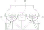
FIG. 1 is a schematic view of a centrifugal compressor according to one embodiment provided herein;
FIG. 2 is a schematic structural view of a rotor according to one embodiment provided herein;
FIG. 3 is a schematic structural view of a stator according to one embodiment provided herein;
FIG. 4 is a schematic structural view of a gearbox according to one embodiment provided herein.
The reference numerals are expressed as:
1. a frame; 2. a compression mechanism; 3. a transmission mechanism;
11. a gear box;
21. a stator; 22. a rotor;
31. a driving wheel; 32. driven wheel; 33. a driving shaft;
211. an outer volute; 212. an inner volute; 213. an end cap;
221. a rotating shaft; 222. an impeller; 223. a support bearing; 224. a thrust bearing.
Detailed Description
In the description of the present application, it should be understood that the terms "center," "longitudinal," "transverse," "length," "width," "thickness," "upper," "lower," "front," "rear," "left," "right," "vertical," "horizontal," "top," "bottom," "inner," "outer," "clockwise," "counterclockwise," etc. indicate or are based on the orientation or positional relationship shown in the drawings, merely for convenience of description and to simplify the description, and do not indicate or imply that the devices or elements referred to must have a specific orientation, be configured and operated in a specific orientation, and thus should not be construed as limiting the utility model.
Furthermore, the terms "first," "second," and the like, are used for descriptive purposes only and are not to be construed as indicating or implying a relative importance or implicitly indicating the number of technical features indicated. Thus, a feature defining "a first" or "a second" may explicitly or implicitly include one or more such feature. In the description of the present utility model, the meaning of "a plurality" is two or more, unless explicitly defined otherwise.
In the present application, unless explicitly specified and limited otherwise, the terms "mounted," "connected," "secured," and the like are to be construed broadly, and may be, for example, fixedly connected, detachably connected, or integrally connected; can be mechanically or electrically connected; can be directly connected or indirectly connected through an intermediate medium, and can be communication between two elements. The specific meaning of the above terms in the present utility model can be understood by those of ordinary skill in the art according to the specific circumstances.
The preferred embodiments of the present utility model will be described below with reference to the accompanying drawings, it being understood that the preferred embodiments described herein are for illustration and explanation of the present utility model only, and are not intended to limit the present utility model.
Fig. 1 is a schematic structural view of a centrifugal compressor according to an embodiment of the present application. Fig. 2 is a schematic structural view of a rotor according to an embodiment of the present application. Fig. 3 is a schematic structural view of a stator according to an embodiment of the present application.
As shown in fig. 1 to 3, the centrifugal compressor of the present embodiment includes: the device comprises a frame 1, at least two stages of compression mechanisms 2 and a transmission mechanism 3. At least two stages of compression mechanisms 2 are arranged on the frame 1. Each stage compression mechanism 2 includes a stator 21 and a rotor 22. The rotor 22 includes a rotary shaft 221 and an impeller 222. The impeller 222 is detachably disposed on the rotating shaft 221, and the impeller 222 is located in the stator 21. The stators 21 of the adjacent two-stage compression mechanisms 2 are connected by pipes. The transmission 3 comprises a driving wheel 32 and at least two driven wheels 32. Each driven wheel 32 is detachably disposed on one of the shafts 221. The driving wheel 31 is arranged at the output end of the driving device. The driving wheel 31 is in driving connection with at least two driven wheels 32.
In some examples, as shown in fig. 1, the centrifugal compressor includes a two-stage compression mechanism 2. The two-stage compression mechanisms 2 are symmetrically arranged at the left side and the right side of the frame 1. So establish, structural layout is reasonable, and can satisfy the rotational speed and adjust the demand. It will be appreciated that in other embodiments, the centrifugal compressor may include more than two stages of compression mechanisms 2 or may include only one stage of compression mechanism 2, so long as the requirements of use are met, which is not excessively limited in this embodiment.
In some examples, as shown in fig. 1, the driven wheel 32 on the rotor 22 of each stage of compression mechanism 2 is of a different type. The driven wheels 32 are different in type, and the driving wheel 31 and each driven wheel 32 are different in transmission ratio, and the rotation speed of each rotation shaft 221 is different. The specific model can be calculated according to pneumatic calculation software, the rotation speed required by each rotation shaft 221 under the condition of meeting the outlet pressure is calculated, and then the driven wheel 32 is selected according to the rotation speed of the motor of the driving device and the rotation speeds of the two rotation shafts 221, so that the rotation speed requirement is met. However, in other embodiments, the types of the driven wheels 32 on the rotor 22 of the compression mechanism 2 of each stage may be identical, or at least some of the types of the driven wheels 32 on the rotor 22 of the compression mechanism 2 may be identical, so long as the use requirement can be satisfied, which is not excessively limited in this embodiment.
In some examples, as shown in fig. 1, the impeller 222 on the rotor 22 of each stage of compression mechanism 2 is of a different type. The type distinction of the impeller 222 includes, but is not limited to, distinction of the outer diameter of the impeller 222, distinction of the curved shape of the blades, distinction of the blade size, distinction of the blade density, and the like. The impeller 222 of the rotor 22 of the compression mechanism 2 of each stage of the present embodiment is different in type, and the outlet pressure of the centrifugal compressor can be ensured. In particular, since the inlet volumetric flow of the centrifugal compressor gradually decreases as the gas is compressed, a different impeller is selected for each stage, enabling the outlet pressure of the centrifugal compressor to be ensured. However, in other embodiments, the types of the impellers 222 on the rotor 22 of the compression mechanism 2 of each stage may be identical, or at least some of the types of the impellers 222 on the rotor 22 of the compression mechanism 2 may be identical, so long as the use requirement can be satisfied, which is not limited in this embodiment.
In some examples, as shown in fig. 1 and 2, the impeller 222 is a shrouded impeller, consisting of a disk, shroud, and blades. However, in other embodiments, the impeller 222 may be a semi-open impeller, etc., and this embodiment is not limited thereto.
In some examples, as shown in fig. 1, the centrifugal compressor of the present embodiment is an assembled centrifugal compressor. As a structural form of the compressor, the assembled centrifugal compressor has the characteristics of compact structure, large adjustable range and high single-stage efficiency, and is very suitable for an air energy storage process. It will be appreciated that in other embodiments, the centrifugal compressor may take other forms, and this embodiment is not intended to be limiting in any way.
When the centrifugal compressor provided in this embodiment works, the driving wheel 31 transmits the mechanical energy of the driving device to at least two driven wheels 32 to drive the rotating shaft 221 of the at least two-stage compression mechanism 2 to rotate, so that the impeller 222 on the rotating shaft 221 rotates, and the gas entering the impeller 222 is acted, so as to increase the gas pressure. The rotor 22 adopts a single-wheel single-shaft structural design, so that the load of a shaft system is effectively reduced, the design difficulty of a bearing is reduced, and the operation efficiency of the impeller 222 is ensured. The rotor 22 adopts a single-wheel single-shaft structure, the variable speed adjustment of each stage of compression mechanism 2 can be realized by changing the type of the driven wheel 32 on the rotating shaft 221 of each stage of compression mechanism 2, and the outlet pressure of each stage of compression mechanism 2 can also be regulated by changing the type of the impeller 222 on the rotating shaft 221 of each stage of compression mechanism 2. The shaft system of the centrifugal compressor provided in the embodiment can stably operate under high pressure (the highest using pressure can reach 15MPa (A)), can be suitable for different working conditions and meets the operating requirements of different outlet pressures, and has more reasonable structural design, and can meet the requirements of an air energy storage process.
In some embodiments, referring to fig. 1, the transmission 3 further comprises: at least two backup driven wheels. The backup driven wheel is of a different type than the driven wheel 32.
The alternate driven wheel is arranged in the embodiment, so that the alternate driven wheel can be used for replacement, and the rotating speed of the rotating shaft 221 can be conveniently adjusted, so that different rotating speed requirements can be met.
In some embodiments, referring to fig. 1, each stage of compression mechanism 3 further comprises: at least one spare impeller. The spare impeller is of a different model than impeller 222.
In order to reduce the cost, the multi-stage compression mechanism 2 may share a set of spare impellers. It is not necessary to provide a spare impeller for each stage of compression mechanism 2.
This embodiment can be used for replacement by providing a spare impeller, which facilitates the adjustment of the outlet pressure of the stator 21 to meet different outlet pressure requirements.
In some embodiments, as shown in fig. 1 and 3, the stator 21 includes: an outer volute 211, an inner volute 212, and an end cap 213. The outer volute 211 includes an intake end and an exhaust end. The inner volute 212 is located in the outer volute. Both ends of the inner scroll 212 are respectively communicated with an intake end and an exhaust end of the outer scroll 211. An impeller 222 is located in the inner volute 212 near the air intake end of the outer volute 211. End cap 213 seals the exhaust end of outer volute 122. The end cap 213 is provided with an exhaust port.
In some examples, as shown in fig. 1, the impeller 222 is disposed at one end of the shaft 221 and extends from the inlet end of the outer volute 211 into the inner volute. As shown in fig. 3, the exhaust port in the end cap 213 forms a gas flow path that extends into the inner volute 212 and toward the inlet end of the outer volute 211. The outer side of the exhaust port of the end cap 213 is also provided with a connection structure for connecting a pipe.
In some examples, as shown in fig. 3, the end cap 213 is bolted to the outer volute 211. The arrangement can ensure the connection tightness of the end cover 213 and the outer volute 211 and is convenient to detach.
The stator 21 of the present embodiment has sufficient strength to withstand the pressure of the gas and has good sealing properties to keep the gas from leaking outside, while also having sufficient rigidity to be less prone to deformation.
In some embodiments, as shown in fig. 3, the outer volute 211 is a forging. The forging is to apply pressure to a metal blank by using a forging machine to make the metal blank plastically deformed so as to obtain a workpiece with certain mechanical properties and shape and size. The defects of cast loosening and the like generated in the smelting process of metal can be eliminated through forging, the microstructure is optimized, and meanwhile, the mechanical properties of the forged piece are generally superior to those of castings made of the same materials because the complete metal streamline is preserved.
The outer volute 211 of the embodiment is a forging piece, so that the bearing capacity of the housing can be ensured, and the mechanical property of the outer volute 211 under high pressure can be ensured.
In some embodiments, as shown in fig. 1, the rotating shaft 221 is rotatably disposed on the frame 1 through a support bearing 223 and a thrust bearing 224.
In some examples, as shown in fig. 1, each shaft 221 is mounted on the frame 1 by two support bearings 223. The support bearings 223 on the rotary shaft 221 are located on both sides of the driven wheel 32, respectively. Thus, the operation stability of the rotation shaft 221 can be ensured. It will be appreciated that in other embodiments, each rotating shaft 221 may be mounted on the frame 1 through more than two support bearings 223, which is not limited in this embodiment.
In some examples, as shown in fig. 1, a thrust bearing 224 is disposed at an end of the shaft 221 remote from the impeller 222. This arrangement is advantageous in counteracting the pressure differential across the impeller 222.
The rotating shaft 221 of the embodiment is rotatably arranged on the frame 1 through the support bearing 223 and the thrust bearing 224, so that the running stability of the rotating shaft 221 can be ensured, and the pneumatic thrust generated by the shafting can be effectively reduced.
In some embodiments, as shown in fig. 1, the primary wheel 31 and the secondary wheel 32 are gears. The output of the drive is provided with a drive shaft 33. The driving wheel 31 is arranged on the driving shaft 33, and the driving wheel 31 is meshed with the driven wheel 32 for transmission.
When the centrifugal compressor of this embodiment works, the driving device transmits mechanical energy to the driving wheel 31 through the driving shaft 33, and the driving wheel 31 and the driven wheel 32 are in tooth engagement transmission to drive the impeller 222 on the rotating shaft 221 to rotate, so as to apply work to the gas entering the impeller 222, and improve the gas pressure. In use, the rotational speed requirement of each shaft 221 under the condition of meeting the outlet pressure can be calculated by using pneumatic calculation software, and then the teeth matching of the driving wheel 31 and the driven wheel 32 is performed according to the rotational speed of the motor of the driving device and the rotational speeds of the two shafts 221. Different rotation speed requirements are met through different tooth meshing, and further the running rotation speed requirements are met.
In some embodiments, as shown in fig. 4. The frame 1 includes: a gear box 11. The gearbox 11 carries the compression mechanism 2 and the transmission mechanism 3.
In some examples, as shown in fig. 1, the driving wheel 31 and the driven wheel 32 of the transmission 3 are located in the gear case 11, the rotation shaft 221 is located in the gear case 11, and the stator 21 is fixed on the side of the gear case 11 by bolts.
This arrangement of the present embodiment can make the centrifugal compressor more compact.
In some embodiments, as shown in fig. 1, the axes of rotation 221 of at least two compression mechanisms 2 are parallel to each other.
In some examples, referring to fig. 1, when the number of compression mechanisms 2 is more than two, the rotation shafts 221 of the compression mechanisms 2 are also parallel to each other and distributed along the circumferential direction of the driving wheel 1.
The rotary shafts 221 of at least two compression mechanisms 2 of the present embodiment are parallel to each other, so that the centrifugal compressor can be more compact.
In some embodiments, further comprising: at least one cooler. The coolers are located in the pipe between the stators 21 of the adjacent two-stage compression mechanisms 2.
Specifically, referring to fig. 1, the gas exiting from the right stator 21 is cooled by passing through a pipe into a cooler, and then passes through a pipe into the left stator 21.
In this embodiment, the cooler is provided between the stators 21 of the adjacent two-stage compression mechanisms 2, so that the temperature of the compressed gas can be effectively reduced.
It will be readily appreciated by those skilled in the art that the above advantageous ways can be freely combined and superimposed without conflict.
The foregoing description of the preferred embodiment of the present utility model is not intended to limit the utility model to the particular form disclosed, but on the contrary, the intention is to cover all modifications, equivalents, and alternatives falling within the spirit and scope of the utility model. The foregoing is merely a preferred embodiment of the present application and it should be noted that it will be apparent to those skilled in the art that several modifications and variations can be made without departing from the technical principles of the present application, and these modifications and variations should also be regarded as the scope of the present application.
Claims (10)
1. A centrifugal compressor, comprising:
a frame;
at least two stages of compression mechanisms are arranged on the frame; each stage of compression mechanism comprises a stator and a rotor; the rotor comprises a rotating shaft and an impeller; the impeller is detachably arranged on the rotating shaft and is positioned in the stator; the stators of the adjacent two stages of compression mechanisms are connected through pipelines;
the transmission mechanism comprises a driving wheel and at least two driven wheels; each driven wheel is detachably arranged on one rotating shaft; the driving wheel is arranged at the output end of the driving device; the driving wheel is in transmission connection with the at least two driven wheels.
2. The centrifugal compressor of claim 1, wherein the transmission mechanism further comprises:
and the standby driven wheels are different from the driven wheels in type.
3. The centrifugal compressor of claim 1, wherein the compression mechanism of each stage further comprises:
at least one spare impeller, the spare impeller being of a different model than the impeller.
4. The centrifugal compressor according to claim 1, wherein said stator comprises:
the outer volute comprises an air inlet end and an air outlet end;
an inner volute located in the outer volute; two ends of the inner volute are respectively communicated with an air inlet end and an air outlet end of the outer volute; the impeller is positioned in the inner volute and is close to the air inlet end of the outer volute;
an end cap sealing an exhaust end of the outer volute; and the end cover is provided with an exhaust port.
5. The centrifugal compressor of claim 4, wherein the outer volute is a forging.
6. The centrifugal compressor according to claim 1, wherein the rotary shaft is rotatably provided to the frame through a support bearing and a thrust bearing.
7. The centrifugal compressor according to claim 1, wherein the driving wheel and the driven wheel are gears;
the output end of the driving device is provided with a driving shaft; the driving wheel is arranged on the driving shaft and is in meshed transmission with the driven wheel.
8. The centrifugal compressor according to claim 7, wherein said housing comprises:
and a gear box carrying the compression mechanism and the transmission mechanism.
9. The centrifugal compressor according to claim 1, wherein the rotational axes of said at least two compression mechanisms are parallel to each other.
10. The centrifugal compressor according to claim 1, further comprising:
at least one cooler is located on the conduit between the stators of adjacent two stages of the compression mechanism.
Priority Applications (1)
| Application Number | Priority Date | Filing Date | Title |
|---|---|---|---|
| CN202321078087.5U CN219299549U (en) | 2023-05-08 | 2023-05-08 | Centrifugal compressor |
Applications Claiming Priority (1)
| Application Number | Priority Date | Filing Date | Title |
|---|---|---|---|
| CN202321078087.5U CN219299549U (en) | 2023-05-08 | 2023-05-08 | Centrifugal compressor |
Publications (1)
| Publication Number | Publication Date |
|---|---|
| CN219299549U true CN219299549U (en) | 2023-07-04 |
Family
ID=86956787
Family Applications (1)
| Application Number | Title | Priority Date | Filing Date |
|---|---|---|---|
| CN202321078087.5U Active CN219299549U (en) | 2023-05-08 | 2023-05-08 | Centrifugal compressor |
Country Status (1)
| Country | Link |
|---|---|
| CN (1) | CN219299549U (en) |
-
2023
- 2023-05-08 CN CN202321078087.5U patent/CN219299549U/en active Active
Similar Documents
| Publication | Publication Date | Title |
|---|---|---|
| EP3483450B1 (en) | Multi-stage compressor with turbine section for fuel cell system | |
| US9512849B2 (en) | Multi-stage integrally geared compressor | |
| CN210461110U (en) | Special direct-drive high-speed centrifugal air compressor for vehicle-mounted hydrogen fuel cell | |
| EP2604862A1 (en) | A compressor arrangement | |
| CN113606006A (en) | Supercritical carbon dioxide turbine compression all-in-one machine | |
| CN201916218U (en) | Gear type air compressor for PTA (pure terephthalic acid) device | |
| CN111734630A (en) | Take fuel cell roots formula air compressor machine of energy recuperation function | |
| CN219299549U (en) | Centrifugal compressor | |
| CN110541831A (en) | Multi-stage compressor with turbine section for a fuel cell system | |
| CN214836565U (en) | Compression-expansion coaxial unit and Brayton cycle system | |
| CN115614294A (en) | Megawatt gear box type low-temperature air centrifugal compressor | |
| CN206477997U (en) | A kind of direct-connected oil-free air compressor | |
| CN213176096U (en) | Supercritical carbon dioxide Brayton cycle compressor | |
| CN220890590U (en) | Volute and centrifugal compressor | |
| CN114635866B (en) | Large-scale air separation plant is supporting with tertiary large-traffic coefficient compressor structure | |
| KR101578027B1 (en) | Compressor and energy saving system using the same | |
| KR20190122608A (en) | Turbo Compressor | |
| CN217354806U (en) | Internal tooth speed-up formula centrifugal compressor | |
| CN213205969U (en) | Vehicle-mounted oil-free screw compressor | |
| CN212225573U (en) | Multistage turbine fan for papermaking | |
| CN213953739U (en) | Novel turbocharger | |
| CN219509817U (en) | Integrated integral screw compressor | |
| CN218991904U (en) | Megawatt gear box type low-temperature air centrifugal compressor | |
| CN212225574U (en) | Turbine rotor of multistage turbine fan | |
| CN219953690U (en) | Magnetic suspension centrifugal heat pump compressor with wide frequency conversion operation |
Legal Events
| Date | Code | Title | Description |
|---|---|---|---|
| GR01 | Patent grant | ||
| GR01 | Patent grant |