CN219274603U - Scrap cleaning device of turret milling machine - Google Patents
Scrap cleaning device of turret milling machine Download PDFInfo
- Publication number
- CN219274603U CN219274603U CN202222680255.XU CN202222680255U CN219274603U CN 219274603 U CN219274603 U CN 219274603U CN 202222680255 U CN202222680255 U CN 202222680255U CN 219274603 U CN219274603 U CN 219274603U
- Authority
- CN
- China
- Prior art keywords
- milling machine
- movable plate
- turret milling
- workbench
- cleaning device
- Prior art date
- Legal status (The legal status is an assumption and is not a legal conclusion. Google has not performed a legal analysis and makes no representation as to the accuracy of the status listed.)
- Active
Links
Images


Classifications
-
- Y—GENERAL TAGGING OF NEW TECHNOLOGICAL DEVELOPMENTS; GENERAL TAGGING OF CROSS-SECTIONAL TECHNOLOGIES SPANNING OVER SEVERAL SECTIONS OF THE IPC; TECHNICAL SUBJECTS COVERED BY FORMER USPC CROSS-REFERENCE ART COLLECTIONS [XRACs] AND DIGESTS
- Y02—TECHNOLOGIES OR APPLICATIONS FOR MITIGATION OR ADAPTATION AGAINST CLIMATE CHANGE
- Y02P—CLIMATE CHANGE MITIGATION TECHNOLOGIES IN THE PRODUCTION OR PROCESSING OF GOODS
- Y02P70/00—Climate change mitigation technologies in the production process for final industrial or consumer products
- Y02P70/10—Greenhouse gas [GHG] capture, material saving, heat recovery or other energy efficient measures, e.g. motor control, characterised by manufacturing processes, e.g. for rolling metal or metal working
Abstract
The utility model relates to the field of cleaning equipment and discloses a scrap cleaning device of a turret milling machine, which comprises a turret milling machine body and a turret milling machine body, wherein a workbench is arranged on the turret milling machine body, a plurality of station grooves are formed in the top of the workbench at equal intervals, a movable plate is arranged above the workbench, a plurality of T-shaped brush plates are fixedly arranged at the bottom of the movable plate at equal intervals, the bottom ends of the T-shaped brush plates respectively extend into corresponding station grooves, first bristles are fixedly connected to the T-shaped brush plates, the first bristles are in contact with the inner walls of the station grooves, second bristles are fixedly arranged at the bottom of the movable plate, and the second bristles are in contact with the top of the workbench. The utility model has the following advantages and effects: the automatic cleaning device can automatically clean the scraps on the workbench, can automatically collect the cleaned scraps, does not need the manual collection of the cleaned scraps by a worker, and reduces the labor capacity and the labor time.
Description
Technical Field
The utility model relates to the technical field of cleaning equipment, in particular to a scrap cleaning device of a turret milling machine.
Background
The turret milling machine is a light general metal cutting machine tool, a work table drives a workpiece to move, a high-speed main shaft drives a cutter to rotate for cutting, the turret milling machine has a shape similar to that of a turret, the turret milling machine is compact in structure, small in size and high in flexibility, a milling head can rotate left and right by 90 degrees and back and forth by 45 degrees, a rocker arm can stretch back and forth and rotate 360 degrees in a horizontal plane, the effective working range of the machine tool is greatly improved, and the turret milling machine tool can mill planes, inclined planes, grooves, splines and the like of middle and small parts and is widely applied to industries such as machining, dies, instruments and meters. During the process that the turret milling machine was used, when processing the part, can produce a large amount of piece, piece fall and pile up in milling machine workstation and can influence the use of milling machine to be provided with a plurality of station grooves of type of falling T on the workstation of turret milling machine, there is the piece to fall in the station groove at the in-process of processing. The existing turret milling machine cleans fragments falling inside a workbench of the milling machine by taking cleaning tools, so that the workbench cannot be cleaned timely, the service life of the milling machine is influenced, and meanwhile, the cleaning is troublesome.
The utility model provides a piece clearance structure for turret milling machine to chinese patent bulletin of above-mentioned problem bulletin number CN214350865U which its technical essential is: including the fixed plate, the top welded connection of fixed plate has the workstation, the cutting is equipped with the recess on the workstation, the bottom of workstation is equipped with the bottom plate, be provided with elevation structure on the bottom plate, elevation structure includes the fixed frame, the bottom welded connection of fixed frame has the fixing base, the one end welded connection of fixing base has an electric telescopic handle, sliding connection has the dead lever in the fixed frame, be equipped with clearance structure on the elevation structure, clearance structure includes the fixture block, welded connection has the link on the fixture block, welded connection has the clearance piece on the link, be provided with pushing structure on the fixed frame, the cutting is equipped with the spout in the connecting plate, this clearance structure for turret milling machine is through setting up the elevation structure in the bottom both sides of workstation with clearance structure fixed connection, realize adjusting clearance structure's height through pushing structure in the recess of piling up the piece on the workstation.
The above solution has been found to still have at least the following drawbacks in practice: in the process of automatically cleaning the scraps on the surface of the workbench, the cleaned scraps can not be automatically collected, and the scraps on the workbench can only be cleaned, so that the cleaned scraps are manually collected by a worker, and the labor capacity and the labor time of the worker are increased.
Therefore, it is desirable to design a turret milling machine scrap cleaning device that automatically cleans the scrap on the table and automatically collects the cleaned scrap without manual collection of the cleaned scrap by a worker, thereby reducing labor and labor time.
Disclosure of Invention
The utility model aims to provide a scrap cleaning device of a turret milling machine, which has the effects of automatically cleaning scraps on a workbench and automatically collecting the cleaned scraps.
The technical aim of the utility model is realized by the following technical scheme: the utility model provides a piece cleaning device of turret milling machine, installs the workstation on turret milling machine body and the turret milling machine body, a plurality of station grooves have been seted up to equidistant top of workstation, the top of workstation is provided with the movable plate, equidistant fixed mounting in the bottom of movable plate has a plurality of T type brush boards, the bottom of a plurality of T type brush boards extends to corresponding station inslot respectively, equal fixedly connected with first brush hair on a plurality of T type brush boards, first brush hair contacts with the inner wall in station groove, the bottom fixed mounting of movable plate has the second brush hair, the second brush hair contacts with the top of workstation, the right side of workstation is provided with the adjustment mechanism who is used for driving the movable plate and removes, be provided with the piece collection mechanism that is used for collecting the piece on the movable plate.
Through adopting above-mentioned technical scheme, utilize first brush hair, can brush the station inslot portion clean, utilize the second brush hair, can brush the upper surface of workstation clean, adjustment mechanism is used for steadily supporting the movable plate and can control the movable plate and steadily carry out horizontal migration, realizes the effect of automatic clearance piece to the workstation, and piece collection mechanism is used for collecting the piece of clearing up on the workstation.
The utility model is further provided with: the adjusting mechanism comprises a fixing seat and a sliding seat, wherein the fixing seat is fixedly arranged on the right side wall of the workbench, a sliding groove is formed in the top of the fixing seat, the bottom of the sliding seat is slidably arranged in the sliding groove, and the top of the sliding seat is fixedly connected with the bottom of the moving plate.
By adopting the technical scheme, the sliding seat is used for stably supporting the movable plate at a proper height position.
The utility model is further provided with: the adjusting mechanism further comprises a screw rod and a motor, the screw rod is rotatably arranged in the sliding groove, the sliding seat is sleeved on the screw rod in a threaded mode, the motor is arranged on the front side of the fixing seat, and the front end of the screw rod extends out of the fixing seat and is fixedly connected with the output shaft end of the motor.
Through adopting above-mentioned technical scheme, the motor is used for controlling the lead screw and rotates, utilizes the threaded connection cooperation of lead screw and slide, steerable slide drive movable plate horizontal migration.
The utility model is further provided with: the front side outer wall of fixing base is last fixed mounting has the backup pad, and motor fixed mounting is at the top of backup pad.
Through adopting above-mentioned technical scheme, utilize the backup pad, can support the motor, make things convenient for the installation of motor fixed.
The utility model is further provided with: limiting grooves are formed in the left inner wall and the right inner wall of the sliding groove, limiting rods are fixed on two sides of the sliding seat, and the two limiting rods are respectively and slidably installed in the corresponding limiting grooves.
Through adopting above-mentioned technical scheme, utilize the sliding connection cooperation of gag lever post in the spacing inslot, can carry out spacingly to the sliding travel of slide.
The utility model is further provided with: the debris collecting mechanism comprises a dust collector, a collecting box, a suction header pipe, a conveying transverse pipe, a plurality of suction branch pipes and a discharge pipe, wherein the dust collector and the collecting box are fixedly arranged at the top of the movable plate, one end of the suction header pipe is fixedly connected with the suction end of the dust collector, the conveying transverse pipe is fixedly arranged on the rear side wall of the movable plate through a pipe clamp, one end of the suction header pipe, far away from the dust collector, is fixedly connected with the conveying transverse pipe and communicated with the conveying transverse pipe, the suction branch pipes are fixedly arranged at the bottom of the conveying transverse pipe and are distributed at equal intervals, the suction branch pipes are communicated with the conveying transverse pipe, one end of the discharge pipe is fixedly connected with the discharge end of the dust collector, and one end of the discharge pipe, far away from the dust collector, extends into the collecting box.
Through adopting above-mentioned technical scheme, utilize the suction that produces when the dust catcher operates, can inhale the piece on the workstation and carry to the collection incasement storage, realize collecting the piece, utilize a plurality of equidistant suction branch pipes that set up, can be comprehensive inhale the piece on the workstation and carry to the collection incasement.
The utility model is further provided with: the top of the collecting box is of an opening structure, and a box cover is fixedly arranged on the top of the collecting box through screws.
Through adopting above-mentioned technical scheme, utilize the case lid, conveniently clear up the piece of collection incasement portion to follow-up processing reuse to the piece.
The utility model is further provided with: the top of the case cover is provided with an exhaust hole, and a dust blocking net is fixedly installed in the exhaust hole.
Through adopting above-mentioned technical scheme, utilize the exhaust hole, can make the inside air discharge of entering collecting box, keep off the dirt net and be used for intercepting the piece and block, avoid the piece to discharge from the exhaust hole.
The beneficial effects of the utility model are as follows:
1. according to the utility model, the T-shaped brush plates, the first bristles, the second bristles and the debris collecting mechanism can be controlled to horizontally move by the adjusting mechanism formed by combining the fixing seat, the sliding seat, the screw rod and the motor by the movable plate, so that the upper surface of the workbench and the inside of the plurality of station grooves can be comprehensively and effectively brushed and cleaned, and the effect of automatically cleaning the debris is realized.
2. According to the utility model, the dust collection mechanism formed by combining the dust collector, the collection box, the suction header pipe, the conveying transverse pipe, the plurality of suction branch pipes and the discharge pipe can suck the dust on the workbench into the collection box for storage, so that the automatic dust crushing and collecting function is realized, the subsequent treatment and recycling of the dust are facilitated, the cleaned dust is not required to be manually collected by a worker, the labor amount and the labor time are reduced, the problem that the cleaned dust on the workbench cannot be automatically collected in the automatic cleaning process of the dust on the surface of the workbench, and the cleaned dust can only be cleaned off, so that the cleaned dust is required to be manually collected by the worker later is solved, and the labor amount and the labor time of workers are increased.
Drawings
In order to more clearly illustrate the technical solutions of the embodiments of the present utility model, the drawings required for the description of the embodiments will be briefly described below, and it is apparent that the drawings in the following description are only some embodiments of the present utility model, and other drawings may be obtained according to these drawings without inventive effort for a person skilled in the art.
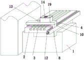
Fig. 1 is a schematic perspective view of the present embodiment.
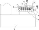
Fig. 2 is a schematic diagram of a front sectional structure of the present embodiment.
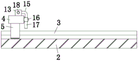
Fig. 3 is an enlarged schematic view of the portion a in fig. 2.
Fig. 4 is a schematic side sectional view of the holder.
Fig. 5 is a schematic side cross-sectional view of a table.
In the figure, 1, a turret milling machine body; 2. a work table; 3. a station groove; 4. a moving plate; 5. a T-shaped brush plate; 6. a first bristle; 7. a second bristle; 8. a fixing seat; 9. a chute; 10. a slide; 11. a screw rod; 12. a motor; 13. a dust collector; 14. a collection box; 15. a suction manifold; 16. a horizontal conveying pipe; 17. a suction manifold; 18. a discharge pipe; 19. a case cover.
Detailed Description
The technical scheme of the present utility model will be clearly and completely described in connection with specific embodiments. It will be apparent that the described embodiments are only some, but not all, embodiments of the utility model. All other embodiments, which can be made by those skilled in the art based on the embodiments of the utility model without making any inventive effort, are intended to fall within the scope of the utility model.
Referring to fig. 1, 2, 3, 4 and 5, the present utility model provides a debris cleaning apparatus for a turret milling machine, comprising: the gun turret milling machine comprises a gun turret milling machine body 1 and a gun turret milling machine body 1, wherein a workbench 2 is arranged on the gun turret milling machine body 1, a plurality of station grooves 3 are formed in the top of the workbench 2 at equal intervals, a movable plate 4 is arranged above the workbench 2, a plurality of T-shaped brush plates 5 are fixedly arranged at the bottom of the movable plate 4 at equal intervals, the number of the T-shaped brush plates 5 is set according to the number of the station grooves 3, first bristles 6 are fixedly connected to the T-shaped brush plates 5, the first bristles 6 are contacted with the inner walls of the station grooves 3, second bristles 7 are fixedly arranged at the bottom of the movable plate 4, the second bristles 7 are contacted with the top of the workbench 2, and the fact that the first bristles 6 and the second bristles 7 can all adopt PA66 nylon wool has the advantages of wear resistance and high temperature resistance is required.
The right side of workstation 2 is provided with adjustment mechanism for steady support movable plate 4 and can drive movable plate 4 horizontal migration, foretell adjustment mechanism includes fixing base 8, slide 10, lead screw 11 and motor 12, fixing base 8 fixed mounting is on the right side wall of workstation 2, spout 9 has been seted up at the top of fixing base 8, slide 10's bottom slidable mounting is in spout 9, slide 10's top and the bottom fixed connection of movable plate 4, lead screw 11 rotates to be installed in spout 9, slide 10 thread bush is established on lead screw 11, motor 12 sets up the front side at fixing base 8, the front end of lead screw 11 extends to outside fixing base 8 and with motor 12's output axle head fixed connection, it is to be noted that motor 12 adopts reversible motor, and then steerable lead screw 11 forward or reverse rotation, fixing base 8's length dimension is greater than workstation 2's length dimension, and spout 9's interior length dimension is also greater than workstation 2's length dimension, and then conveniently adjust movable plate 4 to one side of workstation 2, can not influence the normal use of workstation 2.
Through the structure, the chip cleaning device of the turret milling machine provided by the utility model can be used for effectively brushing and cleaning the workbench 2, and can be used for comprehensively cleaning chips on the workbench 2, in the specific operation, the motor 12 is started to rotate forward, the screw rod 11 is driven to rotate forward by the motor 12, the sliding seat 10 is driven to move the moving plate 4, the plurality of T-shaped brushing plates 5, the first bristles 6 and the second bristles 7 horizontally and forwards, the first bristles 6 on the plurality of T-shaped brushing plates 5 are utilized to brush and clean the interiors of the plurality of station grooves 3, the second bristles 7 are utilized to brush and clean the upper surface of the workbench 2, the first bristles 6 and the second bristles 7 are utilized to push the cleaned chips to move forward in the brushing and cleaning process, the effect of automatically cleaning the chips is realized, and after the chip cleaning on the workbench 2 is completed, the motor 12 is started to rotate reversely by the motor 12, the screw rod 11 is driven to rotate reversely by the sliding seat 10, the moving plate 4, the plurality of T-shaped brushing plates 5, the first bristles 6 and the second bristles 7 horizontally and the second bristles 7 are moved backwards, and the moving plate 4 can be placed on one side of the workbench 2.
Specifically, the front side outer wall of the fixing seat 8 is fixedly provided with a supporting plate, and the motor 12 is fixedly arranged at the top of the supporting plate.
Specifically, the left side inner wall and the right side inner wall of the chute 9 are provided with limit grooves, both sides of the slide seat 10 are fixed with limit rods, and the two limit rods are respectively and slidably arranged in the corresponding limit grooves.
The movable plate 4 is provided with a debris collecting mechanism for collecting the debris on the workbench 2, the debris collecting mechanism comprises a dust collector 13, a collecting box 14, a suction header 15, a conveying transverse pipe 16, a plurality of suction branch pipes 17 and a discharge pipe 18, wherein the dust collector 13 and the collecting box 14 are fixedly arranged at the top of the movable plate 4, one end of the suction header 15 is fixedly connected with the suction end of the dust collector 13, the conveying transverse pipe 16 is fixedly arranged on the rear side wall of the movable plate 4 through a pipe clamp, one end of the suction header 15, far away from the dust collector 13, is fixedly connected with and communicated with the conveying transverse pipe 16, the suction branch pipes 17 are fixedly arranged at the bottom of the conveying transverse pipe 16 and are distributed at equal intervals, the suction branch pipes 17 are communicated with the conveying transverse pipe 16, one end of the discharge pipe 18 is fixedly connected with the discharge end of the dust collector 13, and one end of the discharge pipe 18, far away from the dust collector 13, extends into the collecting box 14.
Specifically, the top of the collecting box 14 is of an open structure, and a box cover 19 is fixedly mounted on the top of the collecting box 14 by screws.
Specifically, the top of case lid 19 has seted up the exhaust hole, and the fixed mounting has the dust blocking net in the exhaust hole.
Through the structure, the chip cleaning device of the turret milling machine provided by the utility model can automatically and comprehensively collect chips on the workbench 2 in the effective brushing cleaning process of the workbench 2, so that the chips on the workbench 2 can be conveniently processed and reused later, the cleaned chips are not required to be manually collected by a worker, the labor amount and the labor time are reduced, and in the specific operation, the function of automatically crushing and collecting chips stored in the workbench 2 is realized by controlling the horizontal movement of the movable plate 4, the plurality of T-shaped brushing plates 5, the first bristles 6 and the second bristles 7 in the process of brushing the chips on the workbench 2, the movable plate 4 also drives the dust collector 13, the collecting box 14, the suction manifold 15, the conveying transverse pipe 16, the plurality of suction branch pipes 17 and the discharge pipe 18 to horizontally move, and the dust collector 13 is started to operate, and the chips on the workbench 2 can be controlled to be sucked into the plurality of suction branch pipes 17 by the suction force generated during the operation of the dust collector 13 and then sequentially pass through the conveying transverse pipe 16, the suction manifold 15, the dust collector 13 and the discharge pipe 18 to the collecting box 14, and the function of automatically crushing and collecting chips stored in the collecting box is realized after the surface cleaning of the workbench 2 is completed, and the dust collector 13 is closed.
Specifically, a control switch is installed on the turret milling machine body 1, the motor 12, the dust collector 13 and the control switch are electrically connected with an external power line through wires to form a loop, and the control switch can control the start and stop and the forward and reverse rotation of the motor 12 and also can control the start and the stop of the dust collector 13.
The utility model provides a dust cleaning device of a turret milling machine. The principles and embodiments of the present utility model have been described herein with reference to specific examples, which are intended to be merely illustrative of the methods of the present utility model and their core ideas. It should be noted that it will be apparent to those skilled in the art that various modifications and adaptations of the utility model can be made without departing from the principles of the utility model and these modifications and adaptations are intended to be within the scope of the utility model as defined in the following claims.
Claims (8)
1. The utility model provides a piece cleaning device of turret milling machine, its characterized in that, install workstation (2) on including turret milling machine body (1) and turret milling machine body (1), a plurality of station grooves (3) have been seted up to equidistant top of workstation (2), the top of workstation (2) is provided with movable plate (4), equidistant fixed mounting in bottom of movable plate (4) has a plurality of T type brush boards (5), a plurality of the bottom of T type brush board (5) extends to respectively in corresponding station groove (3), a plurality of all fixedly connected with first brush hair (6) on T type brush board (5), first brush hair (6) with the inner wall in station groove (3) contacts, the bottom fixed mounting of movable plate (4) has second brush hair (7), second brush hair (7) with the top of workstation (2) contacts, the right side of workstation (2) is provided with and is used for driving movable plate (4) to remove adjustment mechanism, be provided with on movable plate (4) and be used for collecting the piece.
2. The turret milling machine debris cleaning device of claim 1, wherein: the adjusting mechanism comprises a fixing seat (8) and a sliding seat (10), wherein the fixing seat (8) is fixedly arranged on the right side wall of the workbench (2), a sliding groove (9) is formed in the top of the fixing seat (8), the bottom of the sliding seat (10) is slidably arranged in the sliding groove (9), and the top of the sliding seat (10) is fixedly connected with the bottom of the movable plate (4).
3. A turret milling machine scrap cleaning apparatus in accordance with claim 2 wherein: the adjusting mechanism further comprises a screw rod (11) and a motor (12), the screw rod (11) is rotatably installed in the sliding groove (9), the sliding seat (10) is sleeved on the screw rod (11) in a threaded mode, the motor (12) is arranged on the front side of the fixed seat (8), and the front end of the screw rod (11) extends out of the fixed seat (8) and is fixedly connected with the output shaft end of the motor (12).
4. A turret milling machine scrap cleaning apparatus in accordance with claim 3 wherein: the front side outer wall of the fixing seat (8) is fixedly provided with a supporting plate, and the motor (12) is fixedly arranged at the top of the supporting plate.
5. A turret milling machine scrap cleaning apparatus in accordance with claim 2 wherein: limiting grooves are formed in the left inner wall and the right inner wall of the sliding groove (9), limiting rods are fixed on two sides of the sliding seat (10), and the two limiting rods are respectively and slidably installed in the corresponding limiting grooves.
6. The turret milling machine debris cleaning device of claim 1, wherein: the debris collection mechanism comprises a dust collector (13), a collection box (14), a suction header pipe (15), a conveying transverse pipe (16), a plurality of suction branch pipes (17) and a discharge pipe (18), wherein the dust collector (13) and the collection box (14) are fixedly installed at the top of the movable plate (4), one end of the suction header pipe (15) is fixedly connected with the suction end of the dust collector (13), the conveying transverse pipe (16) is fixedly installed on the rear side wall of the movable plate (4) through a pipe clamp, one end of the suction header pipe (15) far away from the dust collector (13) is fixedly connected with the conveying transverse pipe (16) and communicated with the suction branch pipes (17), the suction branch pipes (17) are fixedly installed at the bottom of the conveying transverse pipe (16) and are distributed at equal intervals, one end of the discharge pipe (18) is fixedly connected with the discharge end of the dust collector (13), and one end of the discharge pipe (18) is far away from the dust collector (13) and extends into the collection box (14).
7. The turret milling machine debris cleaning device of claim 6, wherein: the top of the collecting box (14) is of an opening structure, and a box cover (19) is fixedly arranged on the top of the collecting box (14) through screws.
8. The turret milling machine debris cleaning device of claim 7, wherein: the top of the box cover (19) is provided with an exhaust hole, and a dust blocking net is fixedly arranged in the exhaust hole.
Priority Applications (1)
| Application Number | Priority Date | Filing Date | Title |
|---|---|---|---|
| CN202222680255.XU CN219274603U (en) | 2022-10-12 | 2022-10-12 | Scrap cleaning device of turret milling machine |
Applications Claiming Priority (1)
| Application Number | Priority Date | Filing Date | Title |
|---|---|---|---|
| CN202222680255.XU CN219274603U (en) | 2022-10-12 | 2022-10-12 | Scrap cleaning device of turret milling machine |
Publications (1)
| Publication Number | Publication Date |
|---|---|
| CN219274603U true CN219274603U (en) | 2023-06-30 |
Family
ID=86929343
Family Applications (1)
| Application Number | Title | Priority Date | Filing Date |
|---|---|---|---|
| CN202222680255.XU Active CN219274603U (en) | 2022-10-12 | 2022-10-12 | Scrap cleaning device of turret milling machine |
Country Status (1)
| Country | Link |
|---|---|
| CN (1) | CN219274603U (en) |
-
2022
- 2022-10-12 CN CN202222680255.XU patent/CN219274603U/en active Active
Similar Documents
| Publication | Publication Date | Title |
|---|---|---|
| CN110238539B (en) | Full-automatic material cutting robot | |
| CN208408676U (en) | A kind of workbench with cleaning plant | |
| CN211028241U (en) | Milling machine convenient to clearance | |
| CN210476182U (en) | Milling machine workbench for milling notebook computer jig | |
| CN214237334U (en) | Double-step workbench for machining of mechanical drilling | |
| CN219274603U (en) | Scrap cleaning device of turret milling machine | |
| CN211219872U (en) | Dust collector is used in milling machine processing | |
| CN117182740A (en) | Grinding device and grinding method of vertical lathe | |
| CN210172559U (en) | Numerical control lathe cleaning device | |
| CN213351981U (en) | Horizontal milling machine is used in weaving spare part processing convenient to clearance | |
| CN215033690U (en) | Scrap iron collecting device of automatic mechanical processing equipment | |
| CN213561377U (en) | Automatic change numerical control processingequipment | |
| CN213592349U (en) | Magnetic attraction fixed machining table for drilling metal rod | |
| CN212917794U (en) | A shaping machine for iron accessory production | |
| CN212043756U (en) | Horizontal milling and boring machine for machining steel structural member | |
| CN212734286U (en) | Drilling equipment is used in processing of electron radiator convenient to change drill bit | |
| CN112264829A (en) | Double-step workbench for machining of mechanical drilling | |
| CN210968048U (en) | Sweeps processing apparatus for milling machine | |
| CN218284752U (en) | Waste cleaning device of milling machine for machining mechanical parts | |
| CN213563156U (en) | Semi-automatic furniture molding machine | |
| CN219648784U (en) | Milling machine for processing edge die | |
| CN220718138U (en) | Supporting workbench for laser cutting machine | |
| CN218194277U (en) | Plastic uptake tray edge burring device | |
| CN215145769U (en) | Automatic change accurate laser cutting machine | |
| CN219725469U (en) | Cutting machine tool capable of collecting scraps |
Legal Events
| Date | Code | Title | Description |
|---|---|---|---|
| GR01 | Patent grant | ||
| GR01 | Patent grant |