CN219243117U - Display equipment for teaching - Google Patents
Display equipment for teaching Download PDFInfo
- Publication number
- CN219243117U CN219243117U CN202320333430.XU CN202320333430U CN219243117U CN 219243117 U CN219243117 U CN 219243117U CN 202320333430 U CN202320333430 U CN 202320333430U CN 219243117 U CN219243117 U CN 219243117U
- Authority
- CN
- China
- Prior art keywords
- fixedly connected
- display screen
- connecting block
- drive
- worm
- Prior art date
- Legal status (The legal status is an assumption and is not a legal conclusion. Google has not performed a legal analysis and makes no representation as to the accuracy of the status listed.)
- Active
Links
Images


Classifications
-
- Y—GENERAL TAGGING OF NEW TECHNOLOGICAL DEVELOPMENTS; GENERAL TAGGING OF CROSS-SECTIONAL TECHNOLOGIES SPANNING OVER SEVERAL SECTIONS OF THE IPC; TECHNICAL SUBJECTS COVERED BY FORMER USPC CROSS-REFERENCE ART COLLECTIONS [XRACs] AND DIGESTS
- Y02—TECHNOLOGIES OR APPLICATIONS FOR MITIGATION OR ADAPTATION AGAINST CLIMATE CHANGE
- Y02D—CLIMATE CHANGE MITIGATION TECHNOLOGIES IN INFORMATION AND COMMUNICATION TECHNOLOGIES [ICT], I.E. INFORMATION AND COMMUNICATION TECHNOLOGIES AIMING AT THE REDUCTION OF THEIR OWN ENERGY USE
- Y02D10/00—Energy efficient computing, e.g. low power processors, power management or thermal management
Landscapes
- Devices For Indicating Variable Information By Combining Individual Elements (AREA)
Abstract
The utility model discloses a display device for teaching, which comprises a base, wherein two sides of the bottom of the base are fixedly connected with supporting plates, the top of the base is fixedly connected with a placement box, the top of the placement box is provided with a display screen body, two sides of the back of the display screen body are fixedly connected with connecting plates, and a connecting block is arranged in the placement box. According to the utility model, the worm is used for rotating to drive the engaged worm wheel to rotate, the worm wheel is used for rotating to drive the round rod to rotate, the round rod is used for rotating to drive the driving belt pulley to rotate, the driving belt pulley is used for rotating to drive the screw rod to rotate, the screw rod is used for rotating to drive the connecting block to move upwards, the connecting block is used for moving upwards to drive the connecting plate to move upwards, and the connecting plate is used for moving upwards to drive the display screen body to move upwards, so that the advantage of adjusting the height of the display screen is achieved, the functionality of the display screen is improved, and the display screen is convenient for a user to use.
Description
Technical Field
The utility model relates to the technical field of teaching, in particular to display equipment for teaching.
Background
The multimedia teaching all-in-one integrates multiple technologies such as infrared touch technology, intelligent office teaching software, multimedia network communication technology, high-definition flat panel display technology and the like, integrates multiple devices such as a projector, a projection curtain, an electronic whiteboard, a computer, a television, a touch screen and the like into a whole, promotes a traditional display terminal into a man-machine interaction device with comprehensive functions, and can realize writing, annotating, drawing, multimedia entertainment and computer operation by a user through the product, so that a wonderful interaction classroom can be easily deducted by directly opening the device.
The display equipment is needed in student training, teaching and the like, but most of the existing display methods are used for teaching students through lesson preparation files on the display screen, but the existing display screen is installed through bolts, and the height of the display screen cannot be adjusted secondarily after installation, so that the viewing angles of the display screen are different due to the fact that students with different heights watch the display screen in teaching, viewing angles of the students are poor when the students watch the display screen, the students cannot see the content of the display screen clearly, the functionality of the display screen is reduced, and the use of a user is inconvenient.
Therefore, the display equipment needs to be designed and improved, the display screen is effectively prevented from being installed through the bolts, and the height of the display screen cannot be adjusted secondarily after the display screen is installed, so that the phenomenon that the viewing angle is poor when students watch the display screen due to different heights in teaching is caused.
Disclosure of Invention
In order to solve the problems in the prior art, the utility model aims to provide a display device for teaching, which has the advantage of adjusting the height of a display screen, and solves the problems that the display screen is installed through bolts, and the height of the display screen cannot be adjusted for the second time after the installation, so that the viewing angles of students with different heights can be different when teaching, and the viewing angles of the students can be poor when the students view the display screen.
In order to achieve the above purpose, the present utility model provides the following technical solutions: the utility model provides a display device for teaching, includes the base, the equal fixedly connected with backup pad in both sides of base bottom, the top fixedly connected with of base places the case, the top of placing the case is provided with the display screen body, the equal fixedly connected with connecting plate in both sides at display screen body back, the inside of placing the case is provided with the connecting block, the bottom of connecting plate runs through to the inside of placing the case and with the top fixedly connected with of connecting block, the front side fixedly connected with at base top places the board, the inside of placing the case is provided with lifting assembly.
As the preferable mode of the utility model, the lifting component comprises a screw, the bottom of the screw is movably connected with the bottom of the inner wall of the placement box through a bearing, the top of the screw penetrates through the top of the connecting block, the connecting block is in threaded connection with the screw, and the bottom of the surface of the screw is fixedly connected with a driving belt wheel.
As the preferable mode of the utility model, the two sides of the connecting block are fixedly connected with limiting blocks, the two sides of the inner wall of the placement box are provided with limiting grooves, the outer sides of the limiting blocks extend to the inside of the limiting grooves, and the limiting blocks are in sliding connection with the limiting grooves.
As the preferable mode of the utility model, both sides of the top of the placing plate are movably connected with round rods through bearings, the tops of the round rods are fixedly connected with driving pulleys, the driving pulleys are in transmission connection with the driving pulleys through synchronous belts, and the bottoms of the surfaces of the round rods are fixedly connected with worm gears.
As the preferable mode of the utility model, the top of the placing plate is fixedly connected with a double-shaft motor, the output end of the double-shaft motor is fixedly connected with a worm, the worm is meshed with a worm wheel, the outer end of the worm is movably connected with a fixing plate through a bearing, and the bottom of the fixing plate is fixedly connected with the top of the placing plate.
As preferable, the inside of the placing box is provided with two check blocks, the front surface and the back surface of the check blocks are fixedly connected with the front side and the back side of the inner wall of the placing box, and the top of the check blocks is contacted with the bottom of the connecting block.
As the preferable mode of the utility model, the front side of the top of the placing plate is fixedly connected with the protective box, the double-shaft motor is positioned in the protective box, and the top of the protective box is provided with the heat dissipation holes.
Compared with the prior art, the utility model has the following beneficial effects:
1. according to the utility model, the worm is used for rotating to drive the engaged worm wheel to rotate, the worm wheel is used for rotating to drive the round rod to rotate, the round rod is used for rotating to drive the driving belt pulley to rotate, the driving belt pulley is used for rotating to drive the screw rod to rotate, the screw rod is used for rotating to drive the connecting block to move upwards, the connecting block is used for moving upwards to drive the connecting plate to move upwards, and the connecting plate is used for moving upwards to drive the display screen body to move upwards, so that the advantage of adjusting the height of the display screen is achieved, the functionality of the display screen is improved, and the display screen is convenient for a user to use.
2. According to the utility model, through the mutual matching of the screw and the driving belt wheel, the connecting block can be driven to move upwards when the screw is rotated, the connecting block moves upwards to drive the connecting plate to move upwards, the connecting plate moves upwards to drive the display screen body to move upwards, and the display screen body moves upwards to enable students with different heights to achieve the optimal viewing angle.
3. According to the utility model, through the mutual matching of the limiting blocks and the limiting grooves, the limiting of the connecting blocks during movement can be improved, the situation that the connecting blocks can be driven to rotate in the placing box during rotation of the screw is avoided, so that the connecting blocks cannot be lifted normally, and the connecting blocks cannot be driven to adjust the heights of the connecting plates and the display screen body.
4. According to the utility model, through the mutual matching of the round rod, the driving belt pulley and the worm wheel, the round rod can be driven to rotate when the worm wheel is rotated, the round rod rotates to drive the driving belt pulley on the surface to rotate, and the driving belt pulley rotates to drive the driving belt pulley to rotate through the synchronous belt, so that the screw rod can drive the display screen body to achieve the advantage of height adjustment.
5. According to the utility model, when the double-shaft motor is started, the double-shaft motor drives the worm to rotate, the worm rod rotates to drive the meshed worm wheel to rotate, the worm wheel rotates to drive the round rod to rotate, the round rod rotates to drive the driving belt wheel on the surface to rotate, the driving belt wheel rotates to drive the driving belt wheel to rotate through the synchronous belt, and the driving belt wheel rotates so that the screw rod can enable the display screen body to be adjusted in height.
6. According to the utility model, the stop block is arranged, so that the connecting block can be limited, the connecting plate is prevented from contacting with the top of the driving belt pulley when moving downwards, the driving belt pulley can be driven to rotate abnormally, and the stop block can be supported when contacting with the bottom of the connecting block, so that the situation that the stop block is broken due to overlarge stress is prevented.
7. According to the utility model, the double-shaft motor can be protected through the mutual matching of the protective box and the radiating holes, so that the situation that the double-shaft motor is damaged due to the fact that external impurities can enter the inside of the double-shaft motor when the double-shaft motor works is avoided, and the service life of the double-shaft motor is shortened.
Drawings
FIG. 1 is a front view of a base of the present utility model;
FIG. 2 is a cross-sectional view of the placement box of FIG. 1 in accordance with the present utility model;
fig. 3 is an enlarged view of fig. 1 at a in accordance with the present utility model.
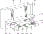
In the figure: 1. a base; 2. a support plate; 3. placing a box; 4. a display screen body; 5. a connecting plate; 6. a connecting block; 7. placing a plate; 8. a lifting assembly; 801. a screw; 802. a transmission belt wheel; 803. a limiting block; 804. a limit groove; 805. a round bar; 806. a driving pulley; 807. a worm wheel; 808. a biaxial motor; 809. a worm; 810. a fixing plate; 811. a stop block; 9. a protective box; 10. and the heat dissipation holes.
Detailed Description
The following description of the embodiments of the present utility model will be made clearly and completely with reference to the accompanying drawings, in which it is apparent that the embodiments described are only some embodiments of the present utility model, but not all embodiments. All other embodiments, which can be made by those skilled in the art based on the embodiments of the utility model without making any inventive effort, are intended to be within the scope of the utility model.
As shown in fig. 1 to 3, the display device for teaching provided by the utility model comprises a base 1, wherein two sides of the bottom of the base 1 are fixedly connected with a supporting plate 2, the top of the base 1 is fixedly connected with a placement box 3, the top of the placement box 3 is provided with a display screen body 4, two sides of the back of the display screen body 4 are fixedly connected with a connecting plate 5, the inside of the placement box 3 is provided with a connecting block 6, the bottom of the connecting plate 5 penetrates through the inside of the placement box 3 and is fixedly connected with the top of the connecting block 6, the front side of the top of the base 1 is fixedly connected with a placement plate 7, and the inside of the placement box 3 is provided with a lifting assembly 8.
Referring to fig. 1 and 2, the lifting assembly 8 comprises a screw 801, the bottom of the screw 801 is movably connected with the bottom of the inner wall of the placement box 3 through a bearing, the top of the screw 801 penetrates through the top of the connecting block 6, the connecting block 6 is in threaded connection with the screw 801, and a driving belt pulley 802 is fixedly connected with the bottom of the surface of the screw 801.
As a technical optimization scheme of the utility model, through the mutual matching of the screw 801 and the driving belt pulley 802, the connecting block 6 can be driven to move upwards when the screw 801 is rotated, the connecting block 6 moves upwards to drive the connecting plate 5 to move upwards, the connecting plate 5 moves upwards to drive the display screen body 4 to move upwards, and the display screen body 4 moves upwards to enable students with different heights to achieve the optimal viewing angle.
Referring to fig. 2, both sides of the connection block 6 are fixedly connected with a limiting block 803, both sides of the inner wall of the placement box 3 are provided with limiting grooves 804, the outer sides of the limiting blocks 803 extend to the inside of the limiting grooves 804, and the limiting blocks 803 are slidably connected with the limiting grooves 804.
As a technical optimization scheme of the utility model, through the mutual matching of the limiting blocks 803 and the limiting grooves 804, the limiting of the connecting blocks 6 during movement can be improved, and the situation that the connecting blocks 6 can be driven to rotate in the placing box 3 when the screw 801 rotates is avoided, so that the connecting blocks 6 cannot be lifted normally, and the connecting blocks 6 cannot drive the connecting plates 5 and the display screen body 4 to adjust the height is avoided.
Referring to fig. 2, both sides of the top of the placement plate 7 are movably connected with a round bar 805 through bearings, the top of the round bar 805 is fixedly connected with a driving pulley 806, the driving pulley 806 is in transmission connection with the driving pulley 802 through a synchronous belt, and the bottom of the surface of the round bar 805 is fixedly connected with a worm wheel 807.
As a technical optimization scheme of the utility model, through the mutual matching of the round bar 805, the driving pulley 806 and the worm wheel 807, the round bar 805 can be driven to rotate when the worm wheel 807 is rotated, the round bar 805 rotates to drive the driving pulley 806 on the surface to rotate, the driving pulley 806 rotates to drive the driving pulley 802 to rotate through the synchronous belt, and the driving pulley 802 rotates to enable the screw 801 to drive the display screen body 4 to achieve the advantage of height adjustment.
Referring to fig. 2, a biaxial motor 808 is fixedly connected to the top of the placement plate 7, a worm 809 is fixedly connected to the output end of the biaxial motor 808, the worm 809 is meshed with the worm wheel 807, a fixing plate 810 is movably connected to the outer end of the worm 809 through a bearing, and the bottom of the fixing plate 810 is fixedly connected to the top of the placement plate 7.
As a technical optimization scheme of the utility model, when the double-shaft motor 808 is started through the mutual matching of the double-shaft motor 808, the worm 809 and the fixing plate 810, the double-shaft motor 808 drives the worm 809 to rotate, the worm 809 rotates to drive the meshed worm wheel 807 to rotate, the worm wheel 807 rotates to drive the round bar 805 to rotate, the round bar 805 rotates to drive the driving belt pulley 806 on the surface to rotate, the driving belt pulley 806 rotates to drive the driving belt pulley 802 to rotate through the synchronous belt, and the driving belt pulley 802 rotates to enable the screw 801 to enable the display screen body 4 to be capable of adjusting the height.
Referring to fig. 2, the inside of the placement box 3 is provided with two stoppers 811, the front surface of the stopper 811 is fixedly connected to the back surface and the front and rear sides of the inner wall of the placement box 3, and the top of the stopper 811 is in contact with the bottom of the connection block 6.
As a technical optimization scheme of the utility model, through the arrangement of the stop block 811, the connecting block 6 can be limited, so that the situation that the connecting plate 5 contacts with the top of the driving belt pulley 802 when moving downwards, and therefore the driving belt pulley 802 can not normally rotate is avoided, and the stop block 811 can also support the connecting block 6 when contacting with the bottom of the connecting block 6, so that the situation that the stop block 803 is broken due to overlarge stress is avoided.
Referring to fig. 3, a protection box 9 is fixedly connected to the front side of the top of the placement plate 7, a double-shaft motor 808 is located inside the protection box 9, and a heat dissipation hole 10 is formed in the top of the protection box 9.
As a technical optimization scheme of the utility model, the double-shaft motor 808 can be protected through the mutual matching of the protective box 9 and the radiating holes 10, so that the situation that the double-shaft motor 808 is damaged due to the fact that external impurities can enter the inside of the double-shaft motor 808 when the double-shaft motor 808 works is avoided, and the service life of the double-shaft motor 808 is shortened.
The working principle and the using flow of the utility model are as follows: when the display screen body 4 is used, a user needs to adjust the height of the display screen body 4, the user starts the double-shaft motor 808, the double-shaft motor 808 starts to drive the worm 809 to rotate, the worm 809 rotates to drive the engaged worm wheel 807 to rotate, the worm wheel 807 rotates to drive the round bar 805 to rotate, the round bar 805 rotates to drive the driving pulley 806 to rotate, the driving pulley 806 rotates to drive the driving pulley 802 through the synchronous belt, the driving pulley 802 rotates to drive the screw 801 to rotate, the screw 801 rotates to drive the connecting block 6 to move upwards, the connecting block 6 moves upwards to drive the connecting plate 5 to move upwards, the connecting plate 5 moves upwards to drive the display screen body 4 to move upwards, when the display screen body 4 moves upwards to reach the optimal height, the user closes the double-shaft motor 808 to limit the display screen body 4, and the user reverses the double-shaft motor 808 to reduce the height of the display screen body 4, and accordingly the advantage of adjusting the height of the display screen body 4 is achieved.
To sum up: this a display device for teaching through setting up base 1, backup pad 2, place case 3, display screen body 4, connecting plate 5, connecting block 6, place board 7, lifting unit 8, screw rod 801, driving pulley 802, stopper 803, spacing groove 804, round bar 805, driving pulley 806, worm wheel 807, biax motor 808, worm 809, fixed plate 810, dog 811, the cooperation of protective housing 9 and louvre 10 is used, has solved the display screen and has all been installed through the bolt, can not adjust the display screen height secondary after the installation to can be because of the student of different heights watches the visual angle of display screen when leading to the teaching different, thereby can appear watching the not good problem of visual angle when perhaps making some students watch the display screen.
It is noted that relational terms such as first and second, and the like are used solely to distinguish one entity or action from another entity or action without necessarily requiring or implying any actual such relationship or order between such entities or actions. Moreover, the terms "comprises," "comprising," or any other variation thereof, are intended to cover a non-exclusive inclusion, such that a process, method, article, or apparatus that comprises a list of elements does not include only those elements but may include other elements not expressly listed or inherent to such process, method, article, or apparatus.
Although embodiments of the present utility model have been shown and described, it will be understood by those skilled in the art that various changes, modifications, substitutions and alterations can be made therein without departing from the principles and spirit of the utility model, the scope of which is defined in the appended claims and their equivalents.
Claims (7)
1. Display equipment for teaching, including base (1), its characterized in that: the utility model discloses a novel electronic device is characterized in that the supporting plate (2) is fixedly connected with both sides of base (1) bottom, place case (3) in the top fixedly connected with of base (1), the top of placing case (3) is provided with display screen body (4), the both sides of display screen body (4) back are all fixedly connected with connecting plate (5), the inside of placing case (3) is provided with connecting block (6), the bottom of connecting plate (5) runs through to the inside of placing case (3) and with the top fixedly connected with of connecting block (6), the front side fixedly connected with at base (1) top places board (7), the inside of placing case (3) is provided with lifting assembly (8).
2. A display device for teaching according to claim 1 and characterized in that: lifting assembly (8) include screw rod (801), the bottom of screw rod (801) is through the bottom swing joint of bearing and placing case (3) inner wall, the top of screw rod (801) is run through to the top of connecting block (6), connecting block (6) and screw rod (801) threaded connection, the bottom fixedly connected with driving pulley (802) on screw rod (801) surface.
3. A display device for teaching according to claim 1 and characterized in that: limiting blocks (803) are fixedly connected to two sides of the connecting block (6), limiting grooves (804) are formed in two sides of the inner wall of the placement box (3), the outer sides of the limiting blocks (803) extend to the inner portions of the limiting grooves (804), and the limiting blocks (803) are in sliding connection with the limiting grooves (804).
4. A display device for teaching according to claim 1 and characterized in that: both sides at the top of the placing plate (7) are movably connected with round bars (805) through bearings, the tops of the round bars (805) are fixedly connected with driving pulleys (806), the driving pulleys (806) are in transmission connection with the driving pulleys (802) through synchronous belts, and worm gears (807) are fixedly connected with the bottoms of the surfaces of the round bars (805).
5. A display device for teaching according to claim 1 and characterized in that: the top fixedly connected with biax motor (808) of placing board (7), the output fixedly connected with worm (809) of biax motor (808), worm (809) and worm wheel (807) meshing, the outer end of worm (809) is through bearing swing joint has fixed plate (810), the bottom of fixed plate (810) and the top fixed connection of placing board (7).
6. A display device for teaching according to claim 1 and characterized in that: the inside of placing case (3) is provided with dog (811), the quantity of dog (811) is two, the front and the back of dog (811) and the front side and the rear side fixed connection of placing case (3) inner wall, the top of dog (811) and the bottom contact of connecting block (6).
7. A display device for teaching according to claim 5 and characterized in that: the front side at the top of the placing plate (7) is fixedly connected with a protective box (9), the double-shaft motor (808) is located inside the protective box (9), and the top of the protective box (9) is provided with a heat dissipation hole (10).
Priority Applications (1)
| Application Number | Priority Date | Filing Date | Title |
|---|---|---|---|
| CN202320333430.XU CN219243117U (en) | 2023-02-28 | 2023-02-28 | Display equipment for teaching |
Applications Claiming Priority (1)
| Application Number | Priority Date | Filing Date | Title |
|---|---|---|---|
| CN202320333430.XU CN219243117U (en) | 2023-02-28 | 2023-02-28 | Display equipment for teaching |
Publications (1)
| Publication Number | Publication Date |
|---|---|
| CN219243117U true CN219243117U (en) | 2023-06-23 |
Family
ID=86839262
Family Applications (1)
| Application Number | Title | Priority Date | Filing Date |
|---|---|---|---|
| CN202320333430.XU Active CN219243117U (en) | 2023-02-28 | 2023-02-28 | Display equipment for teaching |
Country Status (1)
| Country | Link |
|---|---|
| CN (1) | CN219243117U (en) |
-
2023
- 2023-02-28 CN CN202320333430.XU patent/CN219243117U/en active Active
Similar Documents
| Publication | Publication Date | Title |
|---|---|---|
| CN219243117U (en) | Display equipment for teaching | |
| CN101555980B (en) | Flat television wall hanging frame | |
| CN214752685U (en) | Integration concatenation liquid crystal display | |
| CN219140304U (en) | Suspension type teaching all-in-one | |
| CN210860564U (en) | Angle-adjustable fixing support for teaching projector | |
| CN109812665B (en) | Multifunctional lifting device for computer display | |
| CN209712007U (en) | A kind of plug-in tablet computer lifting device | |
| CN215417299U (en) | Multimedia interactive display device | |
| CN220471303U (en) | Artificial intelligence supervisory equipment | |
| CN214037439U (en) | Over-and-under type multimedia device fixing base convenient to installation | |
| CN215636047U (en) | Wall-mounted teaching all-in-one machine | |
| CN220584808U (en) | Movable vertical double-sided multifunctional teaching platform | |
| CN219648177U (en) | Screen dust collector is used in display screen production | |
| CN210691633U (en) | Electronic display screen device for teaching | |
| CN214839588U (en) | Intelligent conference LED display terminal | |
| CN216202133U (en) | LED character display screen for computer | |
| CN216387693U (en) | Network class recording platform with function of automatically adjusting illumination intensity | |
| CN216527605U (en) | Multimedia teaching system | |
| CN210804352U (en) | Touch teaching electronic whiteboard | |
| CN220957445U (en) | Mounting structure of computer office projection equipment | |
| CN214890157U (en) | Projection arrangement for internet education | |
| CN219813480U (en) | A touch-control all-in-one desktop location structure for wisdom classroom | |
| CN220232669U (en) | Outdoor high-brightness LCD multifunctional power interactive all-in-one machine | |
| CN215111669U (en) | Touch conference tablet | |
| CN221034898U (en) | Mounting and fixing device for LED display screen |
Legal Events
| Date | Code | Title | Description |
|---|---|---|---|
| GR01 | Patent grant | ||
| GR01 | Patent grant |