CN219233911U - Die casting die for producing speed reducer gears - Google Patents
Die casting die for producing speed reducer gears Download PDFInfo
- Publication number
- CN219233911U CN219233911U CN202222157455.7U CN202222157455U CN219233911U CN 219233911 U CN219233911 U CN 219233911U CN 202222157455 U CN202222157455 U CN 202222157455U CN 219233911 U CN219233911 U CN 219233911U
- Authority
- CN
- China
- Prior art keywords
- die
- core
- cavity
- groove
- speed reducer
- Prior art date
- Legal status (The legal status is an assumption and is not a legal conclusion. Google has not performed a legal analysis and makes no representation as to the accuracy of the status listed.)
- Active
Links
Images


Landscapes
- Molds, Cores, And Manufacturing Methods Thereof (AREA)
Abstract
The utility model relates to a die casting die technical field especially relates to a die casting die for speed reducer gear production, and it includes that it is used for laminating each other in order to carry out the cover half of compound die, movable mould and be used for forming the die cavity and supply last core and the lower core that metal solution injected with die casting machine connection, lower core is located the cover half orientation the lateral wall of movable mould, go up the core and locate the movable mould is towards the lateral wall of cover half, go up the core with lower core forms the die cavity when the compound die, die cavity and speed reducer gear appearance, size are unanimous, lower die cavity has been seted up to lower core, the fixed filling column that is equipped with of bottom inner wall of lower die cavity, the filling column is close to down the chamfer has been seted up to the circumference lateral wall of die cavity bottom, the chamfer is used for contacting with the die cavity internal metal solution to form the notch chamfer of spline groove. The notch inner wall forming chamfer of spline groove has the effect of reducing the probability of surface scratch caused by the fact that the notch inner wall of spline groove forms a chamfer.
Description
Technical Field
The application relates to the technical field of die casting dies, in particular to a die casting die for producing a gear of a speed reducer.
Background
The speed reducer gear is an important transmission component part on the speed reducer, the overall quality requirement of the overall structure of the speed reducer gear is high in the production process, particularly the hardness and the surface finish of the speed reducer gear, the speed reducer gear belongs to a part which is thin in wall and relatively complex in structure, and is usually made of a metal material, and during production, a metal solution is poured into a die casting die, and a speed reducer gear casting is obtained through cooling and demolding.
As shown in FIG. 1, a conventional speed reducer gear comprises a connecting wheel disc a and a meshing fluted disc b, the meshing fluted disc b is integrally and fixedly arranged on one side wall of the connecting wheel disc a, the connecting wheel disc a and the meshing fluted disc b are concentrically arranged, the outer diameter of the meshing fluted disc b is smaller than that of the connecting wheel disc a, a plurality of meshing teeth b1 are uniformly distributed on the peripheral outer wall of the meshing fluted disc b, a ring groove b2 is formed in the side wall of the meshing fluted disc b, which is far away from the connecting wheel disc, a plurality of communication holes b3 are uniformly formed in the ring groove b2 around the axis of the connecting wheel disc a, the communication holes b3 penetrate through the two opposite side walls of the meshing wheel disc b and the connecting wheel disc a, the circle center of the meshing wheel disc b is separated to obtain a protruding disc b4, a spline groove b5 is formed in the protruding disc b4, the spline groove b5 penetrates through two opposite side walls of the protruding wheel disc b4 and the connecting wheel disc a, a gear shaft on the speed reducer is sleeved with the speed reducer gear, and when the speed reducer gear shaft is sleeved on the gear shaft, the gear shaft is inserted into the spline groove b5, and a chamfer is required to be formed on the inner wall of the groove of the spline groove for facilitating the gear shaft insertion. Currently, the reduction gear is usually subjected to manual machining after being subjected to die-casting forming, and workers are required to control the size of the bevel of the chamfer during machining so as to avoid excessive abrasion of the reduction gear material caused by overlarge bevel formed during chamfering, and meanwhile, the side wall of the edge of the notch of the spline groove is easily scratched.
With respect to the related art described above, the inventors believe that the side walls of the spline groove opening edges are easily scratched when chamfering is performed manually.
Disclosure of Invention
In order to reduce probability of surface scratch caused when the notch inner wall of the spline groove forms a chamfer, the application provides a die casting die for producing a speed reducer gear.
The application provides a die casting die for speed reducer gear production adopts following technical scheme:
the utility model provides a die casting die for speed reducer gear production, includes and is used for laminating each other in order to carry out the cover half of compound die, movable mould and be used for forming the die cavity and supply last core and the lower core that metal solution injected, lower core is located the cover half orientation the lateral wall of movable mould, go up the core and locate the movable mould is towards the lateral wall of cover half, go up the core with form the die cavity down during the compound die of core, the die cavity is unanimous with speed reducer gear appearance, size, lower die cavity has been seted up to lower core, the fixed spliced pole that is equipped with of bottom inner wall of lower die cavity, the spliced pole is close to down the circumference lateral wall of die cavity bottom has been seted up down the inclined plane, the inclined plane is used for contacting with the die cavity internal metal solution to form the notch chamfer of spline groove.
Through adopting above-mentioned technical scheme, when the metal solution gets into in the die cavity and cools off gradually, the metal solution forms in the die cavity and the casting mould that is the same with speed reducer gear appearance and volume, because the metal solution laminating is on the chamfer of filling post when cooling shaping, so form the chamfer on the spline groove opening inner wall of speed reducer gear, do not need to take off the back at the foundry goods and carry out chamfering to reduce the probability of fish tail speed reducer gear surface in the chamfering process.
Optionally, a plurality of upper cavities are formed in the side wall of the upper core towards the lower core, a plurality of lower cavities are formed in the side wall of the lower core towards the upper core, the number of the lower cavities corresponds to that of the upper cavities one by one, and when the mold is closed, the upper cavities and the corresponding lower cavities are matched to form the cavities.
Through adopting above-mentioned technical scheme, form the die cavity when a plurality of last die cavities and a plurality of lower die cavity compound die, because the quantity of die cavity is provided with a plurality of for a plurality of castings can be obtained in compound die casting, have improved the machining efficiency of speed reducer gear foundry goods.
Optionally, an overflow groove is formed in the side wall of the edge of each lower cavity, and the overflow groove is communicated with the lower cavity to allow the metal solution to flow in after filling the cavity.
Through adopting above-mentioned technical scheme, the seting up of overflow launder makes the metal solution fill up the back with lower die cavity, and the metal solution overflows to the overflow launder in for the metal solution in the overflow launder forms the connecting block of being connected with the foundry goods, leaves in order to drive the foundry goods from lower die cavity through the connecting block of digging when drawing of patterns to the foundry goods, and is difficult for causing the fish tail to the surface of foundry goods.
Optionally, the lower core is towards the lateral wall of last core has seted up the solution guiding groove, solution guiding groove and every down the die cavity intercommunication, solution guiding groove includes first runner and second runner, first runner with the buffering cambered surface has been seted up to second runner junction inner wall.
Through adopting above-mentioned technical scheme, in the solution guiding groove flowed into the lower die cavity with the metal solution guide to fill up the die cavity gradually, because the buffering cambered surface has been seted up to the inner wall of first runner and second runner junction, buffering cambered surface is in order to flow the metal solution fast and to buffering drainage when buffering the cambered surface, and the mobility that makes the metal solution flow in the solution guiding groove is better in order to be convenient for can fill up the die cavity clearance.
Optionally, a communicating groove is formed between the solution guiding groove and each lower cavity, the groove bottom of the communicating groove is obliquely arranged upwards, the side wall of the bottom of the groove close to the communicating groove is the lowest end, and the groove opening close to the lower cavity is the highest end.
Through adopting above-mentioned technical scheme, the intercommunication groove is with in the metal solution is carried to lower die cavity from solution guiding groove, because the tank bottom in metal intercommunication groove is the slope setting, so when metal solution flows towards lower die cavity, need the metal solution be located the liquid level in the intercommunication groove and rise gradually and just can get into in the intercommunication groove to the instantaneous buffering of metal solution inflow lower die cavity for metal solution evenly, slowly flows into lower die cavity.
Optionally, a plurality of first exhaust grooves are formed in the side wall, facing the upper core, of the lower core, and the solution guiding grooves are communicated with the outside air by the plurality of first exhaust grooves.
Through adopting above-mentioned technical scheme, first exhaust groove is with solution guiding groove and outside air intercommunication to when making the metal solution flow in solution guiding groove, be difficult for producing the atmospheric pressure in the metal solution groove and cause the hindrance to the flow of metal solution, make things convenient for the metal solution to flow into in the die cavity along the solution guiding groove.
Optionally, a plurality of second exhaust grooves are formed in the side wall, facing the upper core, of the lower core, and the overflow grooves are communicated with the outside air through the second exhaust grooves.
Through adopting above-mentioned technical scheme, the second exhaust hole is with overflow launder and outside air intercommunication for be difficult for forming atmospheric pressure in the overflow launder and cause the hindrance to the metal solution inflow, make the metal solution have better mobility, so that can be fast with the overflow launder full of.
Optionally, a plurality of locating rods are arranged on the lower core, locating holes are formed in the side wall, facing the lower core, of the upper core, the number of the locating holes corresponds to the number of the locating rods one by one, the locating holes are used for inserting the locating rods, and when the locating rods are inserted into the locating holes, the notch of the upper cavity and the notch of the lower cavity are aligned in a mutually anastomotic mode.
By adopting the technical scheme, the positioning rod is inserted into the positioning hole, so that the openings of the upper cavity and the lower cavity can be matched, and the precision of the appearance of the casting formed by cooling the molten metal in the cavity is improved.
In summary, the present application includes at least one of the following beneficial technical effects:
1. when the metal solution enters the cavity and is gradually cooled, the metal solution forms a casting mold with the same shape and volume as those of the gear of the speed reducer in the cavity, and as the metal solution is attached to the inverted inclined surface of the filling column during cooling and forming, the inverted inclined surface is formed on the inner wall of the spline groove opening of the gear of the speed reducer, and chamfering processing is not required after a casting is taken down, so that the probability of scratching the surface of the gear of the speed reducer in the chamfering processing process is reduced;
2. the overflow groove is formed so that the metal solution overflows into the overflow groove after the lower cavity is filled with the metal solution, so that the metal solution in the overflow groove forms a connecting block connected with the casting, the connecting block is scratched to drive the casting to leave from the lower cavity when the casting is demolded, and the surface of the casting is not easy to scratch;
3. the solution guiding groove guides the metal solution to flow into the lower cavity and gradually fills the cavity, and as the inner wall of the joint of the first runner and the second runner is provided with the buffering cambered surface, the buffering cambered surface is used for buffering and draining the metal solution when the metal solution rapidly flows to the buffering cambered surface, so that the mobility of the metal solution flowing in the solution guiding groove is better, and the cavity gap can be filled conveniently.
Drawings
Fig. 1 is a schematic diagram of the overall structure of a reduction gear in the present application.
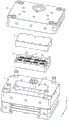
Fig. 2 is an exploded view of the movable mold, the upper core, the lower core, and the fixed mold in the present application.
Fig. 3 is a cross-sectional view of the upper core and the lower core in the longitudinal direction of the front-rear direction in the present application.
Fig. 4 is an enlarged view at a in fig. 3.
Fig. 5 is a side exploded view of the movable mold and the upper, lower and stationary mold cores of the present application.
FIG. 6 is a schematic view of a portion of the upper core structure in the present application.
Fig. 7 is an exploded view of the casting cylinder, the movable mold and the fixed mold in the present application.
Fig. 8 is a schematic side view of the lower core in the present application.
Reference numerals illustrate: 1. a fixed mold; 11. a lower embedded groove; 12. abutting the column; 121. a pouring tank; 2. a movable mold; 21. an upper embedded groove; 22. a plug hole; 23. a casting cylinder; 231. an abutting portion; 232. a plug-in part; 3. an upper core; 31. an upper cavity; 32. forming a bulge; 321. a second inverted slope; 33. positioning holes; 4. a lower core; 41. a lower cavity; 411. a communication groove; 42. a packed column; 421. an inverted slope; 43. a solution guiding groove; 431. a first flow passage; 432. a second flow passage; 433. buffering cambered surfaces; 44. an overflow trough; 441. a connecting block; 45. a first exhaust groove; 46. a second exhaust groove; 47. a positioning rod; 5. a cavity.
Detailed Description
The present application is described in further detail below in conjunction with figures 2-8. In this embodiment, the direction indicated by the z-axis of the coordinate axis is the upper direction, the direction opposite to the z-axis is the lower direction, the direction indicated by the y-axis is the front side, and the direction opposite to the y-axis is the rear side.
The embodiment of the application discloses a die casting die for speed reducer gear production. Referring to fig. 2-4, a die casting mold for gear production of a speed reducer comprises a fixed mold 1, a movable mold 2, an upper core 3 and a lower core 4, wherein the lower core 4 is connected with the fixed mold 1, the upper core 3 is connected with the movable mold 2, when the fixed mold 1 and the movable mold 2 are moved in opposite directions in a mold closing direction, the upper core 3 and the lower core 4 are attached to form a cavity 5, the cavity 5 is used for molten metal injection to form a casting with the shape and the size consistent with those of the gear of the speed reducer, the lower core 4 is provided with a lower cavity 41, the inner wall of the bottom of the lower cavity 41 is fixedly provided with a filling column 42, the circumferential side wall of the filling column 42, which is close to the inner wall of the bottom of the lower cavity 41, is provided with an inverted slope 421, a spline groove is formed when molten metal is formed on the circumferential side of the filling column 42, and a notch chamfer of the spline groove is formed at the inverted slope 421, so that the step of chamfering processing at the notch of the subsequent spline groove of the casting is omitted, and surface scratches are not easy to be caused by chamfering processing.
Referring to fig. 2 and 5, the upper side wall of the fixed mold 1 is provided with a lower insert groove 11, the shape of the notch of the lower insert groove 11 is consistent with the shape of the lower core 4, the lower insert groove 11 is provided with an upper insert groove 21 at the lower side of the movable mold 2, the upper insert groove 21 is provided with an upper core 3, when the upper core 3 is positioned in the upper insert groove 21, the horizontal circumferential side wall of the upper core 3 is abutted against the horizontal inner wall of the upper insert groove 21, the lower side wall of the upper core 3 is provided with an upper cavity 31, the opening of the upper cavity 31 is aligned with the lower cavity 41, the fixed mold 1 and the movable mold 2 are respectively connected with a die casting machine, the upper core 3 is abutted against the opposite side wall of the lower core 4 when the movable mold 2 and the fixed mold 1 are closed, and the upper cavity 31 is aligned with the opening of the lower cavity 41 to form the cavity 5.
Referring to fig. 5 and 6, the inclined surface 421 on the filling column 42 is inclined from top to bottom in a direction away from the axis of the filling column 42, so that the inner wall of the notch on the other side of the spline groove can also have an inclined angle when the casting is formed, the forming protrusion 32 is integrally formed on the inner wall of the inner side of the upper cavity 31 facing the lower side, the shape of the forming protrusion 32 is consistent with the vertical cross section of the filling column 42, the vertical cross section of the filling column 42 is consistent with the opening shape of the spline groove, when the upper core 3 is abutted with the lower core 4, the upper end surface of the filling column 42 is abutted with the lower side wall of the forming protrusion 32, the second inclined surface 321 is formed on the lower side edge side of the forming protrusion 32, and the inclined direction of the second inclined surface 321 is opposite to the inclined direction of the inclined surface 421, so that when the metal solution is formed in the cavity 5, the two inner walls of the notch of the spline groove are both formed with chamfers.
Referring to fig. 2 and 5, in order to improve the die casting production efficiency of the gear of the speed reducer, the upper side wall of the lower core 4 is provided with a plurality of lower cavities 41, and correspondingly, the lower side wall of the upper core 3 is provided with a plurality of upper cavities 31, the number of the upper cavities 31 corresponds to the number of the lower cavities 41 one by one, in this embodiment, the number of the lower cavities 41 is described by taking eight as an example, the eight upper cavities 31 are divided into two rows, four in each row, and two adjacent lower cavities 41 are arranged at intervals.
Referring to fig. 5, in order to keep the openings of the upper cavity 31 and the lower cavity 41 aligned in the vertical direction during mold clamping, a plurality of positioning holes 33 are formed in the lower side wall of the upper core 3, a plurality of positioning rods 47 are inserted into the lower core 4, the number of the positioning rods 47 is identical to that of the positioning holes 33, the positioning rods 47 are inserted into the positioning holes 33, and when the positioning rods 47 are inserted into the positioning holes 33, the openings of the upper cavity 31 are exactly aligned with the openings of the lower cavity 41, and the inner walls of the edges of the openings are mutually matched. In this embodiment, the number of the positioning holes 33 is four, and four positioning rods 47 are respectively and fixedly arranged on the side walls of the lower core 4 close to four opposite angles, the four positioning rods 47 are mutually perpendicular to the upper side wall of the lower core 4, and the circumferential side walls of the positioning rods 47 are attached to the inner walls of the corresponding positioning holes 33, so that relative sliding in the horizontal direction is not easy to occur between the upper core 3 and the lower core 4.
Referring to fig. 7, an insertion hole 22 is formed in an upper side wall of the movable mold 2 near a front side edge, the insertion hole 22 penetrates through an upper side wall and a lower side wall of the movable mold 2, a casting cylinder 23 is inserted into the insertion hole 22, the casting cylinder 23 comprises an abutting portion 231 and an insertion portion 232, the abutting portion 231 is located at the lower side of the insertion portion 232, the insertion portion 232 is inserted into the insertion hole 22, the outer diameter of the abutting portion 231 is larger than the outer diameter of the insertion portion 232, and therefore when the insertion portion 232 is inserted into the insertion hole 22, the abutting portion 231 abuts against the movable mold 2 to limit, and the casting cylinder 23 and the movable mold 2 are kept relatively fixed. The upper side wall of the fixed die 1, which is close to the front side edge, is fixedly connected with an abutting column 12, a pouring groove 121 is formed in the upper end face of the abutting column 12, an upper side notch of the pouring groove 121 is aligned with an end opening of the pouring barrel in the vertical direction, a solution guide groove 43 is formed in the upper side wall of the lower die core 4, a notch on one side of the solution guide groove 43 is communicated with a lower side notch of the pouring groove, the solution guide groove 43 is communicated with each lower die cavity 41, and therefore when metal solution is poured, the metal solution sequentially enters the pouring barrel 23, the pouring groove, the solution guide groove 43 and the lower die cavities 41, and the lower die cavities 41 are slowly filled with the die cavities 5.
Referring to fig. 8, the solution guiding slot 43 includes a first flow channel 431 and a second flow channel 432, two second flow channels 432 are provided, the inner walls of the joints between the two second flow channels 432 and the first flow channel 431 may be right-angled or arc-shaped, in this embodiment, the arc-shaped arrangement is described as an example, and the inner walls of the joints between the first flow channel 431 and the second flow channel 432 are provided with a buffering cambered surface 433.
Correspondingly, each lower cavity 41 is communicated with the first flow channel 431 through a communicating groove 411, metal solution enters the lower cavity 41 from the inside of the first flow channel 431, the groove bottom of the first flow channel 431 is obliquely arranged, the groove bottom of the first flow channel 431 is provided with a lowest end and a highest end in the vertical direction, the lowest end is communicated with the first flow channel 431, the highest end is communicated with the lower cavity 41, and therefore the communicating groove 411 is further used for buffering the metal solution flowing to the lower cavity 41, the metal solution uniformly flows into the lower cavity 41, and the metal solution has better filling fit on the inner wall of the lower cavity 41.
Referring to fig. 8, the inner wall of each lower cavity 41 is provided with a corresponding overflow groove 44, when the metal solution in the lower cavity 41 is filled for the first time, the metal solution flows into the overflow grooves 44 first, and finally the whole cavity 5 is filled, so that after cooling and forming, a connecting block 441 is formed in the overflow grooves 44, the connecting block 441 is connected with the side wall of the casting, the casting can be removed by pulling the connecting block 441, and surface scratches are not easily caused on the casting.
Referring to fig. 8, in order to make the metal solution in the first flow channel 431 have good fluidity, further, the upper sidewall of the lower core 4 is provided with the first air discharge groove 45, the first air discharge groove 45 is provided with two places, the two first air discharge grooves 45 are communicated with the two first flow channels 431, and the notch of one end of the first air discharge groove 45, which is far away from the first flow channel 431, is communicated with the outside air, so that a pressure difference is not easy to form between the first flow channel 431 and the outside air, which causes obstruction to the metal solution flow, and the depths of the two first air discharge grooves 45 are small, so that the metal solution is not easy to flow into the first air discharge groove 45 while the air discharge is enabled.
Referring to fig. 8, the upper side wall of the lower core 4 is provided with a plurality of second air discharge grooves 46, the number of the second air discharge grooves 46 is plural, in this embodiment, the second air discharge grooves 46 are described by taking five as an example, the five second air discharge grooves 46 are communicated with the corresponding overflow grooves 44, two overflow grooves 44 near the rear side and in the middle are difficult to open the second air discharge grooves 46 to communicate with the outside due to being surrounded by the first flow channel 431 and the second flow channel 432, the two second air discharge grooves 46 communicated with the two overflow grooves 44 near the front side are arranged in a communicating manner, and the second air discharge grooves 46 are opened so that the metal solution flowing into the overflow grooves 44 keeps good fluidity, so that the metal solution can fill the overflow grooves 44.
The implementation principle of the die casting die for producing the speed reducer gear is as follows: when the movable die 2 and the fixed die 1 are matched, the upper die cavity 31 and the lower die cavity 41 are matched to form the die cavity 5, the inner wall of the bottom of the lower die cavity 41 is provided with a filling column 42, and an inclined plane is formed in the circumferential side wall in filling, so that after molten metal is molded in the die cavity 5, the obtained speed reducer gear cast forms a chamfer angle on the inner wall of a notch of a spline groove, the forming protrusion 32 in the upper die cavity 31 is provided with a second inverted inclined plane 321, and the inner wall of the notch on the other side of the spline groove is also molded with a chamfer angle, so that the cast does not need chamfering, and the surface scratch of the cast is not easy to be caused by chamfering.
The foregoing are all preferred embodiments of the present application, and are not intended to limit the scope of the present application in any way, therefore: all equivalent changes in structure, shape and principle of this application should be covered in the protection scope of this application.
Claims (8)
1. A die casting die for speed reducer gear production, its characterized in that: including being connected with die casting machine and being used for laminating each other in order to carry out cover half (1), movable mould (2) and be used for forming die cavity (5) and supply last core (3) and lower core (4) that the metal solution was poured into, lower core (4) are located cover half (1) orientation the lateral wall of movable mould (2), go up core (3) and locate movable mould (2) orientation the lateral wall of cover half (1), go up core (3) with lower core (4) form die cavity (5) when the compound die, die cavity (5) are unanimous with speed reducer gear appearance, size, lower die cavity (41) have been seted up to lower core (4), the bottom inner wall of lower die cavity (41) is fixed to be equipped with filling column (42), filling column (42) are close to down circumference lateral wall of die cavity (41) bottom has seted up down inclined plane (421), inclined plane (421) are used for contacting with the metal solution in die cavity (5) to form the notch chamfer of spline groove.
2. A die casting die for speed reducer gear production according to claim 1, characterized in that: the upper mold core (3) is provided with a plurality of upper mold cavities (31) towards the side wall of the lower mold core (4), the lower mold core (4) is provided with a plurality of lower mold cavities (41) towards the side wall of the upper mold core (3), the number of the lower mold cavities (41) corresponds to that of the upper mold cavities (31) one by one, and when the mold is closed, the upper mold cavities (31) are matched with the corresponding lower mold cavities (41) to form a mold cavity (5).
3. A die casting die for speed reducer gear production according to claim 2, characterized in that: and the side wall of the edge of each lower cavity (41) is provided with an overflow groove (44), and the overflow grooves (44) are communicated with the lower cavities (41) so that the metal solution flows in after filling the cavities (5).
4. A die casting die for speed reducer gear production according to claim 3, characterized in that: the lower mold core (4) is provided with a solution guide groove (43) towards the side wall of the upper mold core (3), the solution guide groove (43) is communicated with each lower mold cavity (41), the solution guide groove (43) comprises a first flow passage (431) and a second flow passage (432), and the inner wall of the joint of the first flow passage (431) and the second flow passage (432) is provided with a buffering cambered surface (433).
5. The die casting die for producing speed reducer gears according to claim 4, wherein: a communicating groove (411) is formed between the solution guiding groove (43) and each lower cavity (41), the groove bottom of the communicating groove (411) is obliquely upwards arranged, the side wall of the bottom of the groove close to the communicating groove (411) is the lowest end, and the groove opening close to the lower cavity (41) is the highest end.
6. The die casting die for producing speed reducer gears according to claim 4, wherein: the side wall of the lower core (4) facing the upper core (3) is provided with a plurality of first exhaust grooves (45), and the solution guide grooves (43) are communicated with the outside air by the first exhaust grooves (45).
7. A die casting die for speed reducer gear production according to claim 3, characterized in that: the lower core (4) is provided with a plurality of second exhaust grooves (46) towards the side wall of the upper core (3), and the overflow grooves (44) are communicated with the outside air by the second exhaust grooves (46).
8. A die casting die for speed reducer gear production according to claim 2, characterized in that: the lower mold core (4) is provided with a plurality of positioning rods (47), the upper mold core (3) faces the side wall of the lower mold core (4) and is provided with positioning holes (33), the number of the positioning holes (33) corresponds to the number of the positioning rods (47) one by one, the positioning holes (33) are used for inserting the positioning rods (47), and when the positioning rods (47) are inserted into the positioning holes (33), the upper mold cavity (31) and the notch of the lower mold cavity (41) are aligned in a mutually anastomotic mode.
Priority Applications (1)
| Application Number | Priority Date | Filing Date | Title |
|---|---|---|---|
| CN202222157455.7U CN219233911U (en) | 2022-08-15 | 2022-08-15 | Die casting die for producing speed reducer gears |
Applications Claiming Priority (1)
| Application Number | Priority Date | Filing Date | Title |
|---|---|---|---|
| CN202222157455.7U CN219233911U (en) | 2022-08-15 | 2022-08-15 | Die casting die for producing speed reducer gears |
Publications (1)
| Publication Number | Publication Date |
|---|---|
| CN219233911U true CN219233911U (en) | 2023-06-23 |
Family
ID=86840192
Family Applications (1)
| Application Number | Title | Priority Date | Filing Date |
|---|---|---|---|
| CN202222157455.7U Active CN219233911U (en) | 2022-08-15 | 2022-08-15 | Die casting die for producing speed reducer gears |
Country Status (1)
| Country | Link |
|---|---|
| CN (1) | CN219233911U (en) |
-
2022
- 2022-08-15 CN CN202222157455.7U patent/CN219233911U/en active Active
Similar Documents
| Publication | Publication Date | Title |
|---|---|---|
| CN112658210A (en) | Sectional casting method for subway bogie special-shaped steel casting | |
| CN219233911U (en) | Die casting die for producing speed reducer gears | |
| CN209578070U (en) | A kind of casting die for bend pipe casting | |
| CN209918854U (en) | Forming die for manufacturing hydraulic shaft core of gear box | |
| CN204209069U (en) | A kind of engine cylinder cover casting mould | |
| CN208467217U (en) | A kind of multi-slide die casting | |
| CN205587613U (en) | Tectorial membrane sand mo(u)ld utensil of cast stainless steel thin wall spare | |
| CN209935807U (en) | Sand mold for casting engine cylinder block | |
| CN109047721B (en) | Low-pressure casting die for vehicle box body | |
| CN108673061B (en) | A kind of preparation method of silicon oil clutch shell | |
| CN210547979U (en) | Die casting die of polisher head shell | |
| CN217258034U (en) | Mould for forming hollow-out structure of conical ring | |
| CN207873039U (en) | A kind of mold for producing Metal earphone shell | |
| CN216397911U (en) | Differential shell sand mould | |
| CN214557188U (en) | Casting mould for reducing deformation of thin-wall flat plate casting | |
| CN217803034U (en) | Injection molding die for three-way pipe fitting | |
| CN211276437U (en) | Mold for producing magnesium alloy blank with circular arc thin-wall structure | |
| CN218015643U (en) | Casting die utensil of electric automobile switching mouth that charges | |
| CN217777652U (en) | Die provided with guide structure and used for processing bathroom products | |
| CN213794152U (en) | Magnetic steel frame die structure | |
| CN218134801U (en) | Casting die utensil of camera shell | |
| CN220612268U (en) | Casting uniform cooling die | |
| CN217252719U (en) | Die for manufacturing power supply shell | |
| CN211709918U (en) | Double-hole lock cylinder production mold | |
| CN220717741U (en) | Casting mold with insert router shell |
Legal Events
| Date | Code | Title | Description |
|---|---|---|---|
| GR01 | Patent grant | ||
| GR01 | Patent grant |