CN219227496U - Photovoltaic power generation board mounting support structure - Google Patents
Photovoltaic power generation board mounting support structure Download PDFInfo
- Publication number
- CN219227496U CN219227496U CN202320246499.9U CN202320246499U CN219227496U CN 219227496 U CN219227496 U CN 219227496U CN 202320246499 U CN202320246499 U CN 202320246499U CN 219227496 U CN219227496 U CN 219227496U
- Authority
- CN
- China
- Prior art keywords
- fixing
- support structure
- fixed
- rod
- plate
- Prior art date
- Legal status (The legal status is an assumption and is not a legal conclusion. Google has not performed a legal analysis and makes no representation as to the accuracy of the status listed.)
- Active
Links
Images

Classifications
-
- Y—GENERAL TAGGING OF NEW TECHNOLOGICAL DEVELOPMENTS; GENERAL TAGGING OF CROSS-SECTIONAL TECHNOLOGIES SPANNING OVER SEVERAL SECTIONS OF THE IPC; TECHNICAL SUBJECTS COVERED BY FORMER USPC CROSS-REFERENCE ART COLLECTIONS [XRACs] AND DIGESTS
- Y02—TECHNOLOGIES OR APPLICATIONS FOR MITIGATION OR ADAPTATION AGAINST CLIMATE CHANGE
- Y02E—REDUCTION OF GREENHOUSE GAS [GHG] EMISSIONS, RELATED TO ENERGY GENERATION, TRANSMISSION OR DISTRIBUTION
- Y02E10/00—Energy generation through renewable energy sources
- Y02E10/50—Photovoltaic [PV] energy
Abstract
The utility model provides a photovoltaic power generation plate mounting support structure which comprises a support structure body, wherein the support structure body comprises fixing plates, support plates are welded between the fixing plates, mounting holes are formed in the support plates and the fixing plates, fixing grooves are formed in the fixing plates, fixing columns are fixed on the inner walls of the fixing grooves, rotating sleeves are slidably arranged on the fixing columns, fastening screws are arranged on the rotating sleeves, fixing rods and supporting rods are welded on the rotating sleeves respectively, and the height of the supporting rods is higher than that of the fixing rods. The photovoltaic power generation plate mounting support structure comprises a fixing column, a rotating sleeve, a fixing rod, a supporting point, a supporting rod and a supporting rod.
Description
Technical Field
The utility model relates to the field of photovoltaic power generation plate installation equipment, in particular to a photovoltaic power generation plate installation supporting structure.
Background
The photovoltaic power generation is a technology for directly converting light energy into electric energy by utilizing the photovoltaic effect of a semiconductor interface, and mainly comprises a solar panel, a controller and an inverter, wherein main components are composed of electronic components, solar cells are packaged and protected after being connected in series to form a large-area solar cell assembly, and then the solar cell assembly is matched with the components such as a power controller to form the photovoltaic power generation panel, so that a supporting structure is needed to be matched and installed when the power generation panel is installed.
According to the photovoltaic power generation board mounting support structure disclosed in patent document with the application number of CN217469845U, the photovoltaic power generation board mounting support structure comprises a support plate and a mounting support base body, a fixed plate is welded above the mounting support base body, two sides of the fixed plate are provided with lower fixing screw holes, an adjusting chute is arranged in the fixed plate, a center-of-gravity reinforcing seat is arranged in the middle of the upper part of the adjusting chute, a guiding telescopic rod is arranged in the telescopic spring during use, the telescopic height of the telescopic spring can be guided through the guiding telescopic rod, elastic shrinkage is more stable, and the supporting force of the telescopic spring is increased.
According to the technical scheme, when the support frame is used, the left-right inclination angle of the support frame cannot be changed, and when the width of the power generation plate is large or narrow, the support frame cannot be subjected to inclination adjustment, so that adjustment and installation of different power generation plates cannot be met.
Disclosure of Invention
Aiming at the defects of the prior art, the utility model aims to provide a photovoltaic power generation plate mounting support structure, so as to solve the problems in the prior art.
In order to achieve the above object, the present utility model is realized by the following technical scheme: the utility model provides a photovoltaic power generation board mounting support structure, includes the supporting structure body, the supporting structure body includes the fixed plate, the welding has the backup pad between the fixed plate, all open the mounting hole on backup pad and the fixed plate, it has the fixed slot to open on the fixed plate, be fixed with the fixed column on the inner wall of fixed slot, slidable mounting has the rotation cover on the fixed column, install fastening screw on the rotation cover, it has dead lever and bracing piece to overlap to weld respectively to rotate, the height that highly is higher than the dead lever of bracing piece.
Further, the tops of the fixing rod and the supporting rod are movably provided with a connecting plate, and the connecting plate is provided with a fixing hole.
Further, openings are formed in two sides of the fixing plate, and the openings are connected with the fixing grooves.
Further, the width of the opening is matched with the widths of the fixing rod and the supporting rod, and the supporting rod and the fixing rod are obliquely matched with the inner wall of the opening.
Further, threaded holes are formed in one ends of the fixing rod and the supporting rod, and the threaded holes are formed in the fixing rod and the supporting rod in three directions.
Further, the spliced pole is installed in the inside rotation of screw hole, install the screw thread post on the spliced pole, screw thread post and screw hole rotary fit, the one end welding of spliced pole is on the connecting plate.
The utility model has the beneficial effects that: the utility model relates to a photovoltaic power generation plate mounting support structure, which comprises a fixed plate; a support plate; a mounting hole; a fixing groove; fixing the column; a rotating sleeve; a fastening screw; a fixed rod; a support rod; a connecting plate; a fixing hole; an opening; a threaded hole; a connecting column; and (5) a threaded column.
1. The photovoltaic power generation plate mounting support structure comprises a fixing column, a rotating sleeve, a fixing rod, a supporting point, a supporting rod and a supporting rod.
2. This photovoltaic power generation board mounting support structure, when power generation board width is different, inclines bracing piece and dead lever to the opening of corresponding position department, can outwards or inwards slope simultaneously, the span width between the apron connecting plate realizes the fixed mounting to different width power generation boards.
3. This photovoltaic power generation board mounting support structure, the screw hole inside at different inclination is installed to the connecting plate cooperation spliced pole, and the position that the screw hole used is opposite with dead lever and bracing piece slope rotatory angle to bracing piece and dead lever and power generation board connection installation after this cooperation slope.
Drawings
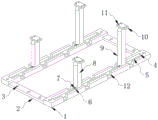
FIG. 1 is a schematic view of a photovoltaic panel mounting support structure according to the present utility model;
FIG. 2 is a schematic view of a structure of the photovoltaic panel mounting support structure according to the present utility model after the support rods and the fixing rods are inclined;
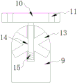
FIG. 3 is a schematic view of a structure of a photovoltaic panel mounting support structure of the present utility model after vertical mounting of a connection post;
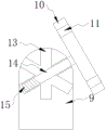
FIG. 4 is a schematic view of a structure of a photovoltaic panel mounting support structure according to the present utility model after a connection post is mounted obliquely;
in the figure: 1. a fixing plate; 2. a support plate; 3. a mounting hole; 4. a fixing groove; 5. fixing the column; 6. a rotating sleeve; 7. a fastening screw; 8. a fixed rod; 9. a support rod; 10. a connecting plate; 11. a fixing hole; 12. an opening; 13. a threaded hole; 14. a connecting column; 15. and (5) a threaded column.
Detailed Description
The utility model is further described in connection with the following detailed description, in order to make the technical means, the creation characteristics, the achievement of the purpose and the effect of the utility model easy to understand.
Referring to fig. 1 to 4, the present utility model provides a technical solution: the utility model provides a photovoltaic power generation board mounting support structure, includes the supporting structure body, the supporting structure body includes fixed plate 1, the welding has backup pad 2 between the fixed plate 1, all open on backup pad 2 and the fixed plate 1 has mounting hole 3, it has fixed slot 4 to open on the fixed plate 1, be fixed with fixed column 5 on the inner wall of fixed slot 4, slidable mounting has rotation cover 6 on the fixed column 5, install fastening screw 7 on the rotation cover 6, it has dead lever 8 and bracing piece 9 to weld respectively on the rotation cover 6, the height of bracing piece 9 is higher than the height of dead lever 8, the top movable mounting of dead lever 8 and bracing piece 9 has connecting plate 10, it has fixed orifices 11 to open on the connecting plate 10, and the height of bracing piece 9 is higher than dead lever 8, is convenient for power generation board realization slope installation.
In this embodiment, the opening 12 is opened to the both sides of fixed plate 1, the opening 12 is connected with fixed slot 4, the width of opening 12 cooperatees with the width of dead lever 8 and bracing piece 9, bracing piece 9 and dead lever 8 slope cooperatees with the inner wall of opening 12, screw hole 13 has all been opened to the one end of dead lever 8 and bracing piece 9, screw hole 13 is three orientation and opens on dead lever 8 and bracing piece 9, connecting post 14 is installed in the inside rotation of screw hole 13, install threaded post 15 on the connecting post 14, threaded post 15 and screw hole 13 rotary fit, the one end welding of connecting post 14 is on connecting plate 10, connecting plate 10 cooperation spliced pole 14 is installed inside screw hole 13 of different inclination, and the position that screw hole 13 used is opposite with the angle of dead lever 8 and bracing piece 9 slope rotation to bracing piece 9 and dead lever 8 after this cooperation slope are connected with the electricity generation board and are installed.
The device is when using, fix fixed plate 1 in the position of using through backup pad 2, adjust the position of cover 6 on fixed column 5 after the fixed completion, thereby adjust according to the fixed position on the power generation board, rotatory fastening screw 7 after the adjustment is accomplished, the spacing install on fixed column 5 of cover 6 is run through to the one end of fastening screw 7, avoid rotating cover 6 rotatory slope on fixed column 5, after the position adjustment of dead lever 8 and bracing piece 9 is accomplished, according to the width difference of power generation board, inwards or outwards open bracing piece 9 and dead lever 8 simultaneously, when bracing piece 9 and dead lever 8 slope, need slope enter into the inside of opening 12 and carry out spacingly, fix through fastening bolt 7 after the slope, after bracing piece 9 and dead lever 8 slope, need adjust the inclination of connecting plate 10, thereby better contact with the bottom of power generation board, the spliced pole 14 on connecting plate 10 is at the inside rotation of screw hole 13, screw hole 13 cooperatees with the dismantlement or installation, connecting plate 10 cooperation spliced pole 14 is installed in the screw hole 13 inside of different inclination, the position that 13 used and dead lever 8 and 9 are with the opposite slope of rotatory 9 and 9 with the power generation board, install with the inclined connection of this inclined plate 8 and the opposite slope.
While the fundamental and principal features of the utility model and advantages of the utility model have been shown and described, it will be apparent to those skilled in the art that the utility model is not limited to the details of the foregoing exemplary embodiments, but may be embodied in other specific forms without departing from the spirit or essential characteristics thereof. The present embodiments are, therefore, to be considered in all respects as illustrative and not restrictive, the scope of the utility model being indicated by the appended claims rather than by the foregoing description, and all changes which come within the meaning and range of equivalency of the claims are therefore intended to be embraced therein. Any reference sign in a claim should not be construed as limiting the claim concerned.
Furthermore, it should be understood that although the present disclosure describes embodiments, not every embodiment is provided with a separate embodiment, and that this description is provided for clarity only, and that the disclosure is not limited to the embodiments described in detail below, and that the embodiments described in the examples may be combined as appropriate to form other embodiments that will be apparent to those skilled in the art.
Claims (6)
1. The utility model provides a photovoltaic power generation board installation bearing structure, includes the bearing structure body, its characterized in that: the supporting structure body comprises a fixed plate (1), a supporting plate (2) is welded between the fixed plate (1), mounting holes (3) are formed in the supporting plate (2) and the fixed plate (1), a fixed groove (4) is formed in the fixed plate (1), a fixed column (5) is fixed on the inner wall of the fixed groove (4), a rotating sleeve (6) is slidably mounted on the fixed column (5), a fastening screw (7) is mounted on the rotating sleeve (6), a fixed rod (8) and a supporting rod (9) are welded on the rotating sleeve (6) respectively, and the height of the supporting rod (9) is higher than that of the fixed rod (8).
2. A photovoltaic panel mounting support structure according to claim 1, characterized in that: the tops of the fixing rod (8) and the supporting rod (9) are movably provided with a connecting plate (10), and the connecting plate (10) is provided with a fixing hole (11).
3. A photovoltaic panel mounting support structure according to claim 1, characterized in that: openings (12) are formed in two sides of the fixing plate (1), and the openings (12) are connected with the fixing grooves (4).
4. A photovoltaic panel mounting support structure according to claim 3, characterized in that: the width of the opening (12) is matched with the widths of the fixing rod (8) and the supporting rod (9), and the supporting rod (9) and the fixing rod (8) are obliquely matched with the inner wall of the opening (12).
5. A photovoltaic panel mounting support structure according to claim 1, characterized in that: screw holes (13) are formed in one ends of the fixing rod (8) and the supporting rod (9), and the screw holes (13) are formed in the fixing rod (8) and the supporting rod (9) in three directions.
6. The photovoltaic panel mounting support structure of claim 5, wherein: the inside rotation of screw hole (13) is installed spliced pole (14), install threaded post (15) on spliced pole (14), threaded post (15) and screw hole (13) rotary fit, the one end welding of spliced pole (14) is on connecting plate (10).
Priority Applications (1)
| Application Number | Priority Date | Filing Date | Title |
|---|---|---|---|
| CN202320246499.9U CN219227496U (en) | 2023-02-03 | 2023-02-03 | Photovoltaic power generation board mounting support structure |
Applications Claiming Priority (1)
| Application Number | Priority Date | Filing Date | Title |
|---|---|---|---|
| CN202320246499.9U CN219227496U (en) | 2023-02-03 | 2023-02-03 | Photovoltaic power generation board mounting support structure |
Publications (1)
| Publication Number | Publication Date |
|---|---|
| CN219227496U true CN219227496U (en) | 2023-06-20 |
Family
ID=86738808
Family Applications (1)
| Application Number | Title | Priority Date | Filing Date |
|---|---|---|---|
| CN202320246499.9U Active CN219227496U (en) | 2023-02-03 | 2023-02-03 | Photovoltaic power generation board mounting support structure |
Country Status (1)
| Country | Link |
|---|---|
| CN (1) | CN219227496U (en) |
-
2023
- 2023-02-03 CN CN202320246499.9U patent/CN219227496U/en active Active
Similar Documents
| Publication | Publication Date | Title |
|---|---|---|
| CN219227496U (en) | Photovoltaic power generation board mounting support structure | |
| CN109802629B (en) | Single-column type angle-adjustable solar photovoltaic bracket and adjusting method thereof | |
| CN207194538U (en) | New type solar energy adjustable photovoltaic bicycle shed | |
| CN213027923U (en) | Photovoltaic power generation device of easy installation | |
| CN209982402U (en) | Solar photovoltaic power generation board installation device | |
| CN209114967U (en) | It is a kind of can solar power generation building site guardrail | |
| CN216599486U (en) | Supporting platform for photovoltaic power generation engineering installation | |
| CN220067322U (en) | Support adjusting device | |
| CN219576904U (en) | Solar panel fixing device | |
| CN220307154U (en) | Photovoltaic plate structure beneficial to assembly | |
| CN219802238U (en) | Photovoltaic bracket with stable connection | |
| CN215072260U (en) | Fixing block structure for mudflat photovoltaic support and support system thereof | |
| CN219436913U (en) | Photovoltaic power generation board installation construction platform | |
| CN216252603U (en) | Building roof photovoltaic power generation device | |
| CN220234539U (en) | Photovoltaic panel support for quickly installing photovoltaic panel | |
| CN211089538U (en) | Mounting bracket of double-sided power generation photovoltaic module | |
| CN219268770U (en) | Photovoltaic power generation plate | |
| CN214799376U (en) | Photovoltaic energy storage power generation wind-proof sand plate applied to desert gobi | |
| CN217508655U (en) | Base is adjusted to detachable photovoltaic support | |
| CN215682192U (en) | Photovoltaic module convenient to installation | |
| CN219611665U (en) | Photovoltaic power generation board mounting bracket | |
| CN217388617U (en) | Photovoltaic power generation assembly with function of adjusting illumination receiving area | |
| CN219351615U (en) | Integrated photovoltaic power equipment | |
| CN220732655U (en) | Connecting mechanism for connecting photovoltaic panels | |
| CN217428040U (en) | Waterproof cooling type roof photovoltaic power generation support |
Legal Events
| Date | Code | Title | Description |
|---|---|---|---|
| GR01 | Patent grant | ||
| GR01 | Patent grant |