CN219222416U - Burner - Google Patents
Burner Download PDFInfo
- Publication number
- CN219222416U CN219222416U CN202320056327.5U CN202320056327U CN219222416U CN 219222416 U CN219222416 U CN 219222416U CN 202320056327 U CN202320056327 U CN 202320056327U CN 219222416 U CN219222416 U CN 219222416U
- Authority
- CN
- China
- Prior art keywords
- air
- preheating
- channel
- fire cover
- panel
- Prior art date
- Legal status (The legal status is an assumption and is not a legal conclusion. Google has not performed a legal analysis and makes no representation as to the accuracy of the status listed.)
- Active
Links
Images


Classifications
-
- Y—GENERAL TAGGING OF NEW TECHNOLOGICAL DEVELOPMENTS; GENERAL TAGGING OF CROSS-SECTIONAL TECHNOLOGIES SPANNING OVER SEVERAL SECTIONS OF THE IPC; TECHNICAL SUBJECTS COVERED BY FORMER USPC CROSS-REFERENCE ART COLLECTIONS [XRACs] AND DIGESTS
- Y02—TECHNOLOGIES OR APPLICATIONS FOR MITIGATION OR ADAPTATION AGAINST CLIMATE CHANGE
- Y02E—REDUCTION OF GREENHOUSE GAS [GHG] EMISSIONS, RELATED TO ENERGY GENERATION, TRANSMISSION OR DISTRIBUTION
- Y02E20/00—Combustion technologies with mitigation potential
- Y02E20/34—Indirect CO2mitigation, i.e. by acting on non CO2directly related matters of the process, e.g. pre-heating or heat recovery
Abstract
The utility model relates to the technical field of stoves, and particularly discloses a combustor which comprises a panel, a stove head, a gas distribution seat, a fire cover assembly, a blower and a preheating pot frame, wherein the stove head is arranged on the panel, the gas distribution seat is arranged on the stove head, the fire cover assembly is arranged on the gas distribution seat and is used for outputting fuel, the preheating pot frame is supported on the panel and is sleeved on the gas distribution seat and the fire cover assembly, the preheating pot frame is used for supporting a pot, an air preheating channel is arranged in the preheating pot frame, an air inlet interface and an air outlet interface which are communicated with the air preheating channel are also arranged in the preheating pot frame, the output end of the blower is communicated with the air inlet interface, the air outlet interface is used for supplying air to the fuel output by the fire cover assembly, when the fuel is combusted, the preheating pot frame has higher temperature under the heat radiation, and can heat the air passing through the air preheating channel, so that the flame temperature is excessively reduced, heat loss is reduced, and simultaneously under the effect of the blower, sufficient air supply can be ensured, and the combustion efficiency is ensured.
Description
Technical Field
The utility model relates to the technical field of stoves, in particular to a combustor.
Background
The secondary air supply of the kitchen range burner in the market at present adopts a passive supply mode, when the kitchen range burner burns normally, the secondary air supplies oxygen through the groove between the outer ring fire cover and the base, when the burner burns with big fire, the air supply is insufficient, yellow flame is easy to appear, and the heat efficiency is low.
In view of this, there is provided a burner in the prior art, in which an inner ring secondary air slot and an outer ring secondary air passage connected to the output end of a blower are provided on a burner and a burner base, and air is supplied to an inner ring fire through the inner ring secondary air slot for combustion and an outer ring fire for combustion through the outer ring secondary air passage under the driving of the blower, and although the blower can supply a sufficient amount of air, the cooler air absorbs part of heat when the inner ring fire and the outer ring fire are supplied for combustion, resulting in heat loss and reduced combustion efficiency.
Disclosure of Invention
The utility model aims at: a burner is provided to reduce heat loss and to remarkably improve combustion efficiency while ensuring sufficient supply of secondary air.
The utility model provides a combustor, which comprises a panel, a furnace end, an air distribution seat, a fire cover assembly, a blower, a preheating pot frame, an air preheating channel, an air inlet interface and an air outlet interface, wherein the furnace end is arranged on the panel, the air distribution seat is arranged on the furnace end, the fire cover assembly is arranged on the air distribution seat and is used for outputting fuel, the preheating pot frame is supported on the panel, the preheating pot frame is simultaneously sleeved on the air distribution seat and the fire cover assembly, the preheating pot frame is internally provided with the air preheating channel, the air inlet interface and the air outlet interface are respectively communicated with the air preheating channel, the output end of the blower is communicated with the air inlet interface, and the air outlet interface is used for supplying air to the fire cover assembly.
As a preferable technical scheme of the burner, the air preheating channel is spiral, the air inlet interface is communicated with the outer periphery of the air preheating channel, and the air outlet interface is communicated with the inner periphery of the air preheating channel.
As the preferable technical scheme of the combustor, the preheating pot frame is provided with a plurality of air outlet interfaces, the air outlet interfaces are sequentially arranged along the direction of conveying air by the air preheating channel, and the air outlet interfaces are uniformly distributed along the circumferential direction of the preheating pot frame.
As a preferable technical scheme of the burner, the hole diameters of the air outlet interfaces are gradually increased along the direction of conveying air by the air preheating channel.
As a preferable technical scheme of the burner, the blower is supported above the panel; or alternatively, the process may be performed,
the air blower is arranged below the panel, the panel is provided with a through hole, and the air inlet port penetrates through the through hole and is positioned below the panel.
As the preferred technical scheme of combustor, preheat the pot frame including preheat the dish and set up in preheat the pot frame of dish top, the pot frame is used for supporting the pan, air preheat the passageway, the inlet connection with the outlet connection all set up in preheat the dish.
As the preferable technical scheme of the burner, the burner also comprises a water pan sleeved on the burner, wherein the water pan is connected with the burner and is supported on the panel;
the preheating pot rack further comprises a supporting ring connected to the bottom of the preheating disc, and the supporting ring is in sealing fit with the upper surface of the water receiving disc.
As the preferable technical scheme of the burner, a semi-closed space is enclosed among the water receiving disc, the supporting ring and the preheating disc, the air outlet interface is communicated with the semi-closed space, and the semi-closed space is configured to only allow air to be conveyed to one side of the fire cover assembly.
As a preferred technical scheme of the burner, the fire cover assembly comprises an inner fire cover and an outer fire cover, wherein the inner fire cover and the outer fire cover are both arranged on the gas distributing seat;
the burner further comprises an air conveying channel, the air conveying channel comprises a first channel arranged between the air distributing seat and the water receiving disc, a second channel arranged on the air distributing seat, and a third channel arranged between the inner fire cover and the outer fire cover, the first channel, the second channel and the third channel are sequentially communicated, and the semi-closed space is communicated with the first channel.
As the preferable technical scheme of the burner, the air conveying channel further comprises a fourth channel arranged between the air dividing seat and the preheating pot frame and a fifth channel arranged between the outer fire cover and the preheating pot frame, and the semi-closed space is communicated with the fourth channel.
The beneficial effects of the utility model are as follows:
the utility model provides a combustor, wherein an air preheating channel is arranged in a preheating pot frame of the combustor, an air inlet interface and an air outlet interface which are all communicated with the air preheating channel are also arranged in the preheating pot frame, the output end of a blower is communicated with the air inlet interface, the air outlet interface is used for supplying air to fuel output by a fire cover assembly, when the fuel output by the fire cover assembly combusts, the preheating pot frame has higher temperature under the action of heat radiation, and when the blower conveys the air to the air preheating channel of the preheating pot frame, the air exchanges heat with the preheating pot frame to raise the temperature, so that the excessive reduction of flame temperature can be avoided when the air is conveyed to the fire cover assembly, the heat loss is avoided, meanwhile, the sufficient air supply can be ensured under the action of the blower, the full combustion of the fuel is promoted, and the combustion efficiency of the fuel is improved.
Drawings
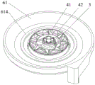
FIG. 1 is a top view of a combustor in an embodiment of the utility model;
FIG. 2 is an isometric view of a combustor in an embodiment of the utility model;
FIG. 3 is an exploded view of a burner in an embodiment of the utility model;
FIG. 4 is a cross-sectional view of the burner of FIG. 1 taken along the direction A-A;
FIG. 5 is a cross-sectional view of the burner of FIG. 1 taken along the B-B direction;
FIG. 6 is a schematic view of a burner supporting a pan according to an embodiment of the present utility model;
FIG. 7 is a schematic view of a partial structure of a burner according to an embodiment of the present utility model;
FIG. 8 is a schematic view of a portion of a combustor according to an embodiment of the present utility model;
FIG. 9 is a schematic view showing a part of the structure of a preheating plate in a burner according to an embodiment of the present utility model;
fig. 10 is a cross-sectional view of a preheating plate in a burner in an embodiment of the present utility model.
In the figure:
1. a panel; 11. a through hole;
2. a burner;
3. an air dividing seat;
4. a fire cover assembly; 41. an inner fire cover; 42. an outer fire cover;
5. a blower;
6. preheating a pot rack; 61. a preheating plate; 611. an air preheating passage; 612. an air inlet interface; 613. an air outlet interface; 614. positioning the bulge; 615. a housing; 616. spiral partition; 62. a pot holder; 621. a base; 622. a support leg; 623. a positioning groove; 63. a support ring; 64. a semi-enclosed space; 65. a nozzle;
7. a water receiving tray;
81. a first channel; 82. a second channel; 83. a third channel; 84. a fourth channel; 85. a fifth channel;
9. a pot.
Detailed Description
The following description of the embodiments of the present utility model will be made apparent and fully in view of the accompanying drawings, in which some, but not all embodiments of the utility model are shown. All other embodiments, which can be made by those skilled in the art based on the embodiments of the utility model without making any inventive effort, are intended to be within the scope of the utility model.
In the description of the present utility model, it should be noted that the directions or positional relationships indicated by the terms "center", "upper", "lower", "left", "right", "vertical", "horizontal", "inner", "outer", etc. are based on the directions or positional relationships shown in the drawings, are merely for convenience of describing the present utility model and simplifying the description, and do not indicate or imply that the devices or elements referred to must have a specific orientation, be configured and operated in a specific orientation, and thus should not be construed as limiting the present utility model. Furthermore, the terms "first," "second," and the like, are used for descriptive purposes only and are not to be construed as indicating or implying relative importance. Wherein the terms "first location" and "second location" are two distinct locations and wherein the first feature is "above," "over" and "over" the second feature includes the first feature being directly above and obliquely above the second feature, or simply indicates that the first feature is level above the second feature. The first feature being "under", "below" and "beneath" the second feature includes the first feature being directly under and obliquely below the second feature, or simply means that the first feature is less level than the second feature.
In the description of the present utility model, it should be noted that, unless explicitly specified and limited otherwise, the terms "mounted," "connected," and "connected" are to be construed broadly, and may be either fixedly connected, detachably connected, or integrally connected, for example; can be mechanically or electrically connected; can be directly connected or indirectly connected through an intermediate medium, and can be communication between two elements. The specific meaning of the above terms in the present utility model will be understood in specific cases by those of ordinary skill in the art.
Embodiments of the present utility model are described in detail below, examples of which are illustrated in the accompanying drawings, wherein like or similar reference numerals refer to like or similar elements or elements having like or similar functions throughout. The embodiments described below by referring to the drawings are illustrative only and are not to be construed as limiting the utility model.
In the burner in the prior art, under the driving of the blower, air is supplied to the inner annular fire for combustion through the inner annular secondary air slot, and is supplied to the outer annular fire for combustion through the outer annular secondary air channel, and the blower can provide enough air, but because the temperature of the air is relatively low, when the inner annular fire and the outer annular fire are supplied for combustion, part of heat can be absorbed by the colder air, and the problems of large heat loss and low combustion efficiency exist.
In this regard, the present embodiment provides a burner capable of reducing heat loss and remarkably improving combustion efficiency on the premise of ensuring sufficient supply of secondary air.
Specifically, as shown in fig. 1 to 6, the burner includes a panel 1, a burner 2, a gas distribution base 3, a fire cover assembly 4, a blower 5, and a preheating pot holder 6. The burner 2 is mounted on the panel 1, the air distribution seat 3 is mounted on the burner 2, the fire cover assembly 4 is mounted on the air distribution seat 3 and is used for outputting fuel, the preheating pot frame 6 is supported on the panel 1 and is sleeved on the air distribution seat 3 and the fire cover assembly 4, the preheating pot frame 6 is used for supporting a pot 9, an air preheating channel 611 is arranged in the preheating pot frame 6, the preheating pot frame 6 is further provided with an air inlet interface 612 and an air outlet interface 613 which are communicated with the air preheating channel 611, the output end of the air blower 5 is communicated with the air inlet interface 612, the air outlet interface 613 is used for supplying air to the fuel output by the fire cover assembly 4, when the fuel output by the fire cover assembly 4 burns, under the action of heat radiation, the preheating pot frame 6 has higher temperature, and the preheating pot frame 6 perform heat exchange to raise the temperature when the air is conveyed to the air preheating channel 611 of the preheating pot frame 6 by the air, so that the flame temperature can be prevented from being excessively lowered when the air is conveyed to the fire cover assembly 4, and the sufficient air supply can be ensured under the effect of the air blower 5, and the fuel combustion efficiency can be promoted.
In this embodiment, the air supplied to the fire cover assembly 4 by the air outlet port 613 is secondary air. The air outlet port 613 can be provided with a nozzle 65 according to actual requirements.
Alternatively, as shown in fig. 4, the blower 5 is disposed below the panel 1 in the present embodiment, the panel 1 is provided with a through hole 11, and the air inlet 612 passes through the through hole 11 and is located below the panel 1, so that the overall appearance of the burner can be ensured. As an alternative thereto, the blower 5 may also be supported above the panel 1.
Optionally, referring to fig. 3 to 8, the preheating pot holder 6 includes a preheating disc 61 and a pot holder 62 disposed above the preheating disc 61, the pot holder 62 is used for supporting the pot 9, and the air preheating channel 611, the air inlet port 612 and the air outlet port 613 are all disposed on the preheating disc 61. Specifically, the pot holder 62 includes a base 621 and a plurality of legs 622 supported on the base 621, and the plurality of legs 622 are uniformly distributed along the circumferential direction of the pot holder 62, wherein four legs 622 are given as an example in the present embodiment, and the number of the legs 622 may be set to be different according to the need in other embodiments. In this embodiment, when the fuel is burned, the legs 622 are in the flame range and can directly absorb heat and transfer to the base 621; in addition, a part of the heat generated by the combustion of the fuel is absorbed by the base 621 by the heat radiation, and the base 621 can transfer the absorbed heat to the preheating tray 61 below and heat the air flowing through the air preheating passage 611 by the preheating tray 61. Preferably, the upper surface of the preheating plate 61 and the lower surface of the base 621 are adhered to ensure good heat transfer effect of the preheating plate 61 and the base 621. It is further preferable that the base 621 and the preheating plate 61 are each of a concave disk-like structure, so that the preheating pot holder 6 has a large heating area to promote the heating effect on the air in the air preheating passage 611. Further preferably, the preheating plate 61 is provided with an annular positioning protrusion 614, the base 621 is provided with an annular positioning groove 623, and the positioning protrusion 614 and the positioning groove 623 are inserted into each other, so as to ensure that the relative positions of the pot holder 62 and the preheating plate 61 are stable, and further ensure that the base 621 and the preheating plate 61 can be stably attached together.
Optionally, referring to fig. 3 to 8, the burner further includes a water pan 7 sleeved on the burner 2, the water pan 7 is connected with the burner 2, and the water pan 7 is supported on the panel 1; the preheating pot holder 6 further comprises a support ring 63 connected to the bottom of the preheating tray 61, and the support ring 63 is in sealing fit with the upper surface of the water receiving tray 7. Wherein, water collector 7 passes through the screw closure with furnace end 2 to be connected, and the outward flange of water collector 7 can be taken on panel 1, and accessible panel 1 and furnace end 2 support water collector 7, and preheat pot frame 6 supports on water collector 7 through support ring 63, and when preheat pot frame 6 top has hot water or debris to drop, can only fall water collector 7, can avoid dropping on the panel 1. Wherein, the support ring 63 and the preheating plate 61 can be integrally arranged or detachably connected.
Through support ring 63 and water collector 7 sealing laminating, support ring 63 and preheating plate 61 sealing laminating encloses between water collector 7, support ring 63 and the preheating plate 61 and establishes into a semi-closed space 64, and the interface of giving vent to anger 613 communicates with this semi-closed space 64, and semi-closed space 64 only allows the air to carry to one side of fire lid subassembly 4, and then stops the air along deviating from one side of fire lid subassembly 4 and return to outside atmosphere in, guarantees that the fuel combustion of the output of fire lid subassembly 4 can be fully supplied with to the air of interface of giving vent to anger 613 output.
As an alternative thereto, the support ring 63 may also be in sealing engagement with the panel 1.
Alternatively, referring to fig. 7 to 10, the air preheating channel 611 is in a spiral shape, the air inlet port 612 is communicated with the outer periphery of the air preheating channel 611, and the air outlet port 613 is communicated with the inner periphery of the air preheating channel 611. Specifically, the preheating plate 61 includes a casing 615 and a spiral partition 616, where the casing 615 has a receiving cavity, the air inlet port 612 and the air outlet port 613 are both disposed in the casing 615, the spiral partition 616 is located in the receiving cavity, and the upper and lower sides of the spiral partition 616 are both connected with the cavity wall of the receiving cavity, so as to form a spiral air preheating channel 611, when air enters the air preheating channel 611 from the air inlet port 612, the air will move along the circumferential direction of the preheating plate 61 for multiple circles to reach the air outlet port 613, and the air has a longer moving path in the air preheating channel 611, so that heat exchange with the preheating plate 61 can be effectively performed, and a higher temperature of the air after being output from the air outlet port 613 is ensured. Wherein the housing 615 and the spiral partition 616 may be integrally provided. Preferably, the preheating pot holder 6 is provided with a plurality of air outlet ports 613, the plurality of air outlet ports 613 are sequentially arranged along the direction in which the air preheating channel 611 conveys air, and the plurality of air outlet ports 613 are uniformly distributed along the circumferential direction of the preheating pot holder 6. This ensures a uniform supply of air to the fuel output from the fire cover assembly 4. Further preferably, the aperture of the plurality of air outlet ports 613 is gradually increased in the direction in which the air preheating passage 611 delivers air. It will be appreciated that as the air passes through the plurality of air outlet ports 613, the air pressure of the air will gradually decrease, and if the apertures of the air outlet ports 613 are consistent, the air flow output by the air outlet ports 613 in the direction along which the air is conveyed along the air preheating channel 611 will gradually decrease, and for this reason, by gradually increasing the apertures of the air outlet ports 613 in the direction along which the air is conveyed along the air preheating channel 611, it can be ensured that the air flow output by the air outlet ports 613 will tend to be balanced.
In other embodiments, the air preheating channel 611 may further include a main channel and a plurality of sub-channels, where the plurality of sub-channels are all in communication with the main channel, and the air inlet port 612 is in communication with the main channel, and the plurality of air outlet ports 613 are in one-to-one communication with the plurality of sub-channels.
The fire cover assembly 4 comprises an inner fire cover 41 and an outer fire cover 42, wherein the inner fire cover 41 and the outer fire cover 42 are arranged on the gas distribution seat 3, and the gas distribution seat 3 is used for respectively conveying fuel provided by the furnace end 2 to the outer fire cover 42 and the inner fire cover 41. The burner still includes the air delivery passageway, the air delivery passageway is including setting up in dividing the first passageway 81 between gas holder 3 and the water collector 7, set up in dividing the second passageway 82 of gas holder 3, and set up in interior fire lid 41 and the third passageway 83 between the outer fire lid 42, first passageway 81, second passageway 82 and third passageway 83 communicate in proper order, semi-enclosed space 64 and first passageway 81 communicate, after the air that the interface 613 output of giving vent to anger gets into semi-enclosed space 64, fuel that the export of fire lid 41 and outer fire lid 42 was supplied with in proper order through first passageway 81, second passageway 82 and third passageway 83 burns, guarantee combustion efficiency.
Optionally, the air delivery channel further includes a fourth channel 84 disposed between the air separation seat 3 and the pre-heating pot holder 6, and a fifth channel 85 disposed between the outer fire cover 42 and the pre-heating pot holder 6, and the semi-enclosed space 64 is further in communication with the fourth channel 84. Because the fuel output by the outer fire cover 42 is more than that output by the inner fire cover 41, a part of air can be independently supplied to the outer fire cover 42 through the fourth channel 84 and the fifth channel 85, so that the air required by the fuel output by the outer fire cover 42 is sufficient, and the combustion efficiency is further ensured.
It is to be understood that the above examples of the present utility model are provided for clarity of illustration only and are not limiting of the embodiments of the present utility model. Other variations or modifications of the above teachings will be apparent to those of ordinary skill in the art. It is not necessary here nor is it exhaustive of all embodiments. Any modification, equivalent replacement, improvement, etc. which come within the spirit and principles of the utility model are desired to be protected by the following claims.
Claims (10)
1. The utility model provides a combustor, includes panel (1), install in furnace end (2) of panel (1), install in divide gas seat (3) of furnace end (2), install in divide gas seat (3) and be used for exporting fire lid subassembly (4) of fuel and air-blower (5), its characterized in that, the combustor still including support in preheat pot frame (6) of panel (1), preheat pot frame (6) cover simultaneously and locate divide gas seat (3) with fire lid subassembly (4), be equipped with air preheating channel (611) in preheat pot frame (6), preheat pot frame (6) still be equipped with all with air preheating channel (611) intercommunication inlet connection (612) and outlet connection (613), the output of air-blower (5) with inlet connection (612) intercommunication, outlet connection (613) are used for giving fire lid subassembly (4) supply air.
2. The burner according to claim 1, wherein the air preheating passage (611) is spiral, the air inlet port (612) is communicated with the outer circumference of the air preheating passage (611), and the air outlet port (613) is communicated with the inner circumference of the air preheating passage (611).
3. Burner according to claim 2, characterized in that the preheating pot holder (6) is provided with a plurality of air outlet ports (613), the plurality of air outlet ports (613) being arranged in sequence in the direction of the air preheating channel (611) for conveying air, and the plurality of air outlet ports (613) being evenly distributed in the circumferential direction of the preheating pot holder (6).
4. A burner according to claim 3, wherein the aperture of a plurality of said air outlet ports (613) is gradually increased in the direction in which said air preheating passage (611) delivers air.
5. Burner according to claim 1, characterized in that said blower (5) is supported above said panel (1); or alternatively, the process may be performed,
the air blower (5) is arranged below the panel (1), the panel (1) is provided with a through hole (11), and the air inlet interface (612) penetrates through the through hole (11) and is positioned below the panel (1).
6. Burner according to claim 1, characterized in that the preheating pot holder (6) comprises a preheating disc (61) and a pot holder (62) arranged above the preheating disc (61), the pot holder (62) being used for supporting a pot (9), the air preheating channel (611), the air inlet interface (612) and the air outlet interface (613) being all arranged in the preheating disc (61).
7. The burner according to claim 6, further comprising a water pan (7) sleeved on the burner (2), wherein the water pan (7) is connected with the burner (2), and the water pan (7) is supported on the panel (1);
the preheating pot rack (6) further comprises a supporting ring (63) connected to the bottom of the preheating disc (61), and the supporting ring (63) is in sealing fit with the upper surface of the water receiving disc (7).
8. Burner according to claim 7, characterized in that a semi-enclosed space (64) is enclosed between the water pan (7), the support ring (63) and the preheating plate (61), the air outlet port (613) being in communication with the semi-enclosed space (64), the semi-enclosed space (64) being configured to allow air to be delivered to only one side of the fire cover assembly (4).
9. Burner according to claim 8, characterized in that the fire cover assembly (4) comprises an inner fire cover (41) and an outer fire cover (42), both the inner fire cover (41) and the outer fire cover (42) being arranged at the gas distributing seat (3);
the burner further comprises an air conveying channel, the air conveying channel comprises a first channel (81) arranged between the air distributing seat (3) and the water receiving disc (7), a second channel (82) arranged on the air distributing seat (3), and a third channel (83) arranged between the inner fire cover (41) and the outer fire cover (42), the first channel (81), the second channel (82) and the third channel (83) are sequentially communicated, and the semi-closed space (64) is communicated with the first channel (81).
10. The burner according to claim 9, wherein the air delivery channel further comprises a fourth channel (84) arranged between the gas separation seat (3) and the pre-heating pan carrier (6), and a fifth channel (85) arranged between the outer fire cover (42) and the pre-heating pan carrier (6), the semi-enclosed space (64) being in communication with the fourth channel (84).
Priority Applications (1)
| Application Number | Priority Date | Filing Date | Title |
|---|---|---|---|
| CN202320056327.5U CN219222416U (en) | 2023-01-09 | 2023-01-09 | Burner |
Applications Claiming Priority (1)
| Application Number | Priority Date | Filing Date | Title |
|---|---|---|---|
| CN202320056327.5U CN219222416U (en) | 2023-01-09 | 2023-01-09 | Burner |
Publications (1)
| Publication Number | Publication Date |
|---|---|
| CN219222416U true CN219222416U (en) | 2023-06-20 |
Family
ID=86742109
Family Applications (1)
| Application Number | Title | Priority Date | Filing Date |
|---|---|---|---|
| CN202320056327.5U Active CN219222416U (en) | 2023-01-09 | 2023-01-09 | Burner |
Country Status (1)
| Country | Link |
|---|---|
| CN (1) | CN219222416U (en) |
-
2023
- 2023-01-09 CN CN202320056327.5U patent/CN219222416U/en active Active
Similar Documents
| Publication | Publication Date | Title |
|---|---|---|
| CN112664981B (en) | Heat shield for stove and gas stove with same | |
| CN108386838A (en) | Burner and gas cooker | |
| CN219222416U (en) | Burner | |
| CN210951313U (en) | Burner and gas stove | |
| CN110608436A (en) | Burner and gas stove | |
| CN115930267A (en) | A kind of burner | |
| CN115992959A (en) | Burner | |
| CN111911927B (en) | Multi-air-channel energy-gathering cover and gas stove | |
| CN213237531U (en) | Stove burner | |
| CN212987211U (en) | Burner for gas stove | |
| CN211060115U (en) | Sectional type efficient combustor and stove | |
| CN112944398A (en) | Dry-burning-preventing flat-plate burner and stove | |
| CN212746462U (en) | Novel furnace end | |
| CN110186042B (en) | Three-ring fire combustor and gas stove | |
| CN218599807U (en) | Energy-gathering pot rack and gas stove with same | |
| CN219014317U (en) | Gas range | |
| CN215336308U (en) | Gas kitchen ranges | |
| CN218993457U (en) | Furnace end of abundant oxygen suppliment | |
| CN112815314B (en) | Burner and gas stove | |
| CN218001578U (en) | Gas kitchen ranges | |
| CN219868002U (en) | Combustion furnace end capable of improving air inlet quantity and gas stove with combustion furnace end | |
| CN212390414U (en) | Energy-gathering plate and stove | |
| CN216047634U (en) | Three-ring fire gas distribution plate and combustor | |
| CN220186890U (en) | Heat accumulating type burner and gas stove provided with same | |
| CN110848688A (en) | Upper air inlet burner |
Legal Events
| Date | Code | Title | Description |
|---|---|---|---|
| GR01 | Patent grant | ||
| GR01 | Patent grant |