CN219217206U - Protective door assembly of construction elevator - Google Patents
Protective door assembly of construction elevator Download PDFInfo
- Publication number
- CN219217206U CN219217206U CN202320815307.1U CN202320815307U CN219217206U CN 219217206 U CN219217206 U CN 219217206U CN 202320815307 U CN202320815307 U CN 202320815307U CN 219217206 U CN219217206 U CN 219217206U
- Authority
- CN
- China
- Prior art keywords
- protective door
- frame
- rod
- block
- door
- Prior art date
- Legal status (The legal status is an assumption and is not a legal conclusion. Google has not performed a legal analysis and makes no representation as to the accuracy of the status listed.)
- Active
Links
Images


Classifications
-
- Y—GENERAL TAGGING OF NEW TECHNOLOGICAL DEVELOPMENTS; GENERAL TAGGING OF CROSS-SECTIONAL TECHNOLOGIES SPANNING OVER SEVERAL SECTIONS OF THE IPC; TECHNICAL SUBJECTS COVERED BY FORMER USPC CROSS-REFERENCE ART COLLECTIONS [XRACs] AND DIGESTS
- Y02—TECHNOLOGIES OR APPLICATIONS FOR MITIGATION OR ADAPTATION AGAINST CLIMATE CHANGE
- Y02B—CLIMATE CHANGE MITIGATION TECHNOLOGIES RELATED TO BUILDINGS, e.g. HOUSING, HOUSE APPLIANCES OR RELATED END-USER APPLICATIONS
- Y02B50/00—Energy efficient technologies in elevators, escalators and moving walkways, e.g. energy saving or recuperation technologies
Landscapes
- Elevator Door Apparatuses (AREA)
Abstract
The utility model relates to the technical field of construction elevators, in particular to a protective door assembly of a construction elevator, which comprises an inner protective door and an outer protective door, wherein the inner protective door comprises a first side frame, transverse frames are arranged at two end positions of one side of the first side frame, a second side frame is arranged on one side of the transverse frames, a combining block is arranged on the inner side of the transverse frames, a winding rod is arranged in the first side frame, a transmission motor is arranged at the position, corresponding to the winding rod, of the upper side of the first side frame, a rolling curtain is arranged on the outer side of the winding rod, an alignment rod is arranged on one side of the combining block, and an alignment hole is formed in the inner side of the second side frame. The inner door is closed and opened through the rolling shutter, the occupied space of the rolling shutter is small, the opening completeness is high, the outer protective door is of a guardrail structure, the opening condition of the inner protective door can be clearly watched, the rolling shutter can be turned over and opened to serve as a base plate, and the rolling shutter is driven to move through the closing block to automatically open and close.
Description
Technical Field
The utility model relates to the technical field of construction elevators, in particular to a protective door assembly of a construction elevator.
Background
The construction elevator is a man-carrying and cargo-carrying construction machine which is frequently used in buildings, is mainly used in various buildings of urban high-rise and super high-rise, is also called a construction elevator, and can greatly improve the safety of the elevator by reducing the risk of falling of internal materials or personnel, for example, chinese patent discloses a construction elevator protective door (grant bulletin number CN 215248972U), after a user enters a hoistway, the technical user of the patent firstly closes a second protective door, then closes a first protective door, the hoistway can be blocked from the outside by locking a bolt, and the hoistway is locked from the inside, so that the external constructor cannot enter the hoistway; the construction elevator is only started to operate when the protective door is closed, so that the protective door is in a closed state when the construction elevator operates, and safety is ensured;
however, the prior art disclosed guard gate assembly for construction elevators has drawbacks in practical use, such as:
(1) the double-door split structure is adopted, the installation occupation space of the door body is large, and the completeness of opening is small, so that the carrying of building materials is affected;
(2) the door plate and the door frame need to be manually locked, so that the convenience of operation is low, and potential safety hazards exist. Accordingly, a guard door assembly of a construction hoist is provided by those skilled in the art to solve the problems set forth in the background art described above.
Disclosure of Invention
The present utility model is directed to a protective door assembly for a construction elevator, which solves the above-mentioned problems of the prior art.
In order to achieve the above purpose, the present utility model provides the following technical solutions:
a protective door assembly of a construction elevator, comprising an inner protective door and an outer protective door, wherein the outer protective door is positioned at the rear side position of the inner protective door;
the inner protective door comprises a first side frame, transverse frames are arranged at two end positions of one side of the first side frame, a second side frame is arranged on one side of the transverse frames, a combined block is arranged on the inner side of the transverse frames, a winding rod is arranged in the first side frame, a transmission motor is arranged at the position, corresponding to the winding rod, of the upper side of the first side frame, a rolling curtain is arranged on the outer side of the winding rod, an alignment rod is arranged on one side of the combined block, and an alignment hole is formed in the inner side of the second side frame;
the outer protective door comprises an outer door frame, and an outer door plate is arranged on the inner side of the outer door frame.
As still further aspects of the utility model: the inner side of the transverse frame is provided with a screw rod, the inner side of the transverse frame is provided with a sliding groove, sliding blocks are arranged at the two ends of the closing block, and a screw rod motor is arranged at the position of the second side frame corresponding to the screw rod.
As still further aspects of the utility model: the clamping groove is formed in the upper side of the outer door frame, the adjusting groove is formed in the rear end of the outer door plate, the sliding rod is mounted on the inner side of the adjusting groove, the clamping block is arranged on the outer side of the sliding rod, and the spring is arranged on the outer side of the sliding rod.
As still further aspects of the utility model: the winding rod rotates at the inner side position of the first side frame through the transmission motor, one end of the rolling curtain is wound at the outer side position of the winding rod, and the other end of the rolling curtain is fixed at one side position of the closing block.
As still further aspects of the utility model: the alignment rod corresponds to the position of the alignment hole, and is clamped at the inner position of the alignment hole.
As still further aspects of the utility model: the sliding block slides at the inner side position of the sliding groove, the screw rod rotates at the outer end position of the sliding block, and the screw rod rotates at the inner side position of the transverse frame through the screw rod motor.
As still further aspects of the utility model: the clamping block corresponds to the clamping groove in position, one end of the sliding rod slides at the inner position of the outer door plate, the clamping block slides at the inner position of the adjusting groove through the sliding rod, and the clamping block is clamped at the inner position of the clamping groove.
Compared with the prior art, the utility model has the beneficial effects that:
(1) the protective door component of the construction lifter disclosed by the utility model is used for closing and opening the inner door through the roller shutter, the occupied space of the roller shutter is small, the opening completeness is high, the outer protective door is of a guardrail structure, the opening condition of the inner protective door can be clearly watched, and the inner protective door can be turned over and opened to serve as a backing plate, so that the carrying operation of building materials is facilitated;
(2) the roller shutter is driven to move through the closing block, and is automatically opened and closed, so that the trouble of manual operation is avoided, and the safety is improved.
Drawings
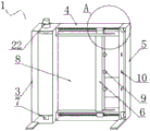
FIG. 1 is a schematic view of a guard door assembly of a construction hoist;
FIG. 2 is a perspective view of an inner guard door of a guard door assembly of a construction elevator;
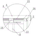
FIG. 3 is a schematic view of the construction elevator guard door assembly of portion A of FIG. 2;
FIG. 4 is a schematic view of the structure of an outer guard door in a guard door assembly of a construction hoist;
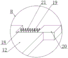
fig. 5 is a schematic view of the construction hoist guard door assembly of part B of fig. 4.
In the figure: 1. an inner protective door; 2. an outer protective door; 3. a first side frame; 4. a transverse frame; 5. a second side frame; 6. combining blocks; 7. a winding rod; 8. a roller shutter; 9. an alignment rod; 10. an alignment hole; 11. an outer door frame; 12. an outer door panel; 13. a chute; 14. a slide block; 15. a screw rod; 16. a screw motor; 17. a clamping groove; 18. an adjustment tank; 19. a slide bar; 20. a clamping block; 21. a spring; 22. and (5) a transmission motor.
Detailed Description
Referring to fig. 1 to 5, in an embodiment of the present utility model, a protective door assembly of a construction hoist includes an inner protective door 1 and an outer protective door 2, the outer protective door 2 is located at a rear side position of the inner protective door 1, the inner protective door 1 includes a first side frame 3, a lateral frame 4 is disposed at two ends of one side of the first side frame 3, a second side frame 5 is disposed at one side of the lateral frame 4, a closing block 6 is disposed at an inner side of the lateral frame 4, a winding rod 7 is disposed in the first side frame 3, a driving motor 22 is mounted at a position corresponding to the winding rod 7 at an upper side of the first side frame 3, a roller shutter 8 is mounted at an outer side of the winding rod 7, an alignment rod 9 is disposed at one side of the closing block 6, an alignment hole 10 is disposed at an inner side of the second side frame 5, the outer protective door 2 includes an outer door frame 11, an outer door plate 12 is mounted at an inner side of the outer door frame 11, the winding rod 7 is rotated at an inner side position of the first side frame 3 by the driving motor 22, one end of the rolling shutter 8 is wound on the outer side of the winding rod 7, the other end of the rolling shutter 8 is fixed on one side of the combining block 6, the aligning rod 9 corresponds to the position of the aligning hole 10, the aligning rod 9 is clamped on the inner position of the aligning hole 10, firstly, the inner protective door 1 is fixed on the mounting position of the elevator door, the outer protective door 2 is fixed on the inner wall of the construction building, the mounting is completed, then, when the elevator drives the inner protective door 1 to move to the position of the outer protective door 2, the outer door plate 12 is rotated to open, the outer door plate 12 is tiled on the ground, the combining block 6 slides on the inner side of the transverse frame 4, the aligning rod 9 is pulled out of the aligning hole 10, the driving motor 22 operates to drive the winding rod 7 to rotate, the winding rod 7 winds the rolling shutter 8, after the building material is carried into the elevator, the driving motor 22 operates to drive the winding rod 7 to rotate, the winding rod 7 releases the rolling shutter 8, the closing block 6 slides on the inner side of the transverse frame 4, the aligning rod 9 is inserted into the aligning hole 10, the closing block 6 drives the rolling shutter 8 to close the inner protective door 1, the outer door plate 12 rotates on the inner side of the outer door frame 11, and the outer protective door 2 is closed.
In fig. 2, 3: the inside of the transverse frame 4 is provided with a screw rod 15, a sliding groove 13 is formed in the inside of the transverse frame 4, sliding blocks 14 are arranged at the positions of two ends of the closing block 6, a screw rod motor 16 is arranged in the second side frame 5 corresponding to the position of the screw rod 15, the sliding blocks 14 slide at the inner side position of the sliding groove 13, the screw rod 15 rotates at the outer end position of the sliding blocks 14, the screw rod 15 rotates at the inner side position of the transverse frame 4 through the screw rod motor 16, the screw rod motor 16 operates to drive the screw rod 15 to rotate, the screw rod 15 rotates at the inner side of the sliding blocks 14, the sliding blocks 14 slide in the sliding grooves 13 to drive the closing block 6 to slide at the inner side of the transverse frame 4, the aligning rod 9 is pulled out of the aligning hole 10, the driving motor 22 operates to drive the winding rod 7 to rotate, the winding rod 7 winds the rolling curtain 8, after the building materials are conveyed into the lifter, the driving motor 22 operates to drive the winding rod 7 to rotate, the winding curtain 8 is released, the screw rod motor 16 operates to drive the screw rod 15 to rotate, the screw rod 15 rotates at the inner side of the sliding blocks 14 slide inside the sliding grooves 13 to drive the closing block 6 to slide at the inner side of the sliding grooves 4, the aligning rod 9 is inserted into the aligning rod 9 to the aligning rod 10 to be inserted into the aligning hole 10 to drive the rolling curtain 8 to close the rolling curtain 1.
In fig. 4, 5: the upper side of outer door frame 11 has seted up draw-in groove 17, the regulating tank 18 has been seted up to the rear end of outer door frame 12, slide bar 19 is installed to the inboard of regulating tank 18, the outside of slide bar 19 is provided with fixture block 20, the outside of slide bar 19 is provided with spring 21, fixture block 20 corresponds with the position of draw-in groove 17, the one end of slide bar 19 slides in the inside position department of regulating tank 18 through slide bar 19, fixture block 20 block in the inside position department of draw-in groove 17, slide bar 19 slides in the inboard of regulating tank 18, spring 21 contracts, fixture block 20 slides out of draw-in groove 17, rotate and open outer door frame 12, outer door frame 12 tiling is to the ground, close piece 6 drives roller shutter 8 and closes interior guard door 1, outer door frame 12 rotates in the inboard of outer door frame 11, slide bar 19 slides in the inboard of regulating tank 18, spring 21 contracts, fixture block 20 slides into regulating tank 18, fixture block 20 moves to the position of draw-in groove 17, the inside of regulating tank 18 is released fixture block 20, spring 21 stretches 19 and promotes fixture block 20 card into the inside of draw-in groove 17, outer guard gate 2 is closed.
The working principle of the utility model is as follows: firstly, the inner protective door 1 is fixed to the mounting position of an elevator door, the outer protective door 2 is fixed to the inner wall of a construction building to finish mounting, then, the elevator drives the inner protective door 1 to move to the position of the outer protective door 2, the sliding rod 19 slides on the inner side of the adjusting groove 18, the spring 21 contracts, the clamping block 20 slides out of the clamping groove 17, the outer door plate 12 is rotated to be opened, the outer door plate 12 is tiled to the ground, the screw motor 16 operates to drive the screw 15 to rotate, the screw 15 rotates in the sliding block 14, the sliding block 14 slides in the sliding groove 13 to drive the closing block 6 to slide on the inner side of the transverse frame 4, the aligning rod 9 is pulled out of the aligning hole 10, the driving motor 22 operates to drive the rolling rod 7 to rotate, the rolling rod 7 is wound around the rolling curtain 8, the building material is conveyed into the elevator, the driving motor 22 operates to drive the rolling rod 7 to rotate, the rolling curtain 8 is loosened, the screw motor 16 operates to drive the screw 15 to rotate, the screw 15 rotates in the sliding block 14, the sliding block 14 slides in the inner side of the sliding groove 13 to drive the closing block 6 to slide on the inner side of the transverse frame 4, the aligning rod 9 is inserted into the aligning hole 10, the sliding block 6 drives the rolling rod 6 to close the rolling rod 8 to drive the rolling rod 12 to rotate in the inner side of the sliding block 21 to the sliding block 13, and the sliding block 20 slides in the inner side of the sliding block 21 to the sliding block 20 to be adjusted to the inner side of the sliding block 20, and the sliding block 20 is stretched out of the sliding block 20.
The foregoing description is only a preferred embodiment of the present utility model, but the scope of the present utility model is not limited thereto, and any person skilled in the art, who is within the scope of the present utility model, should make equivalent substitutions or modifications according to the technical solution of the present utility model and the inventive concept thereof, and should be covered by the scope of the present utility model.
Claims (7)
1. A protective door assembly of a construction elevator, which is characterized by comprising an inner protective door (1) and an outer protective door (2), wherein the outer protective door (2) is positioned at the rear side position of the inner protective door (1);
the inner protective door comprises a first side frame (3) and is characterized in that two ends of one side of the first side frame (3) are respectively provided with a transverse frame (4), one side of the transverse frame (4) is provided with a second side frame (5), the inner side of the transverse frame (4) is provided with a combined block (6), the inner side of the first side frame (3) is provided with a winding rod (7), the upper side of the first side frame (3) is provided with a transmission motor (22) corresponding to the position of the winding rod (7), the outer side of the winding rod (7) is provided with a rolling curtain (8), one side of the combined block (6) is provided with an alignment rod (9), and the inner side of the second side frame (5) is provided with an alignment hole (10);
the outer protective door (2) comprises an outer door frame (11), and an outer door plate (12) is arranged on the inner side of the outer door frame (11).
2. The protective door assembly of the construction elevator according to claim 1, wherein a screw rod (15) is arranged on the inner side of the transverse frame (4), a sliding groove (13) is formed on the inner side of the transverse frame (4), sliding blocks (14) are arranged at two end positions of the closing block (6), and a screw rod motor (16) is arranged in the second side frame (5) at positions corresponding to the screw rod (15).
3. The protective door assembly of the construction elevator according to claim 1, wherein a clamping groove (17) is formed in the upper side of the outer door frame (11), an adjusting groove (18) is formed in the rear end of the outer door frame (12), a sliding rod (19) is mounted on the inner side of the adjusting groove (18), a clamping block (20) is arranged on the outer side of the sliding rod (19), and a spring (21) is arranged on the outer side of the sliding rod (19).
4. A protective door assembly of a construction hoist according to claim 1, characterized in that the winding rod (7) is rotated at an inner side position of the first side frame (3) by a driving motor (22), one end of the rolling shutter (8) is wound at an outer side position of the winding rod (7), and the other end of the rolling shutter (8) is fixed at a side position of the combining block (6).
5. A protective door assembly of a construction hoist according to claim 1, characterized in that the alignment rod (9) corresponds to the position of the alignment hole (10), and the alignment rod (9) is engaged at the inner position of the alignment hole (10).
6. A guard gate assembly of a construction hoist according to claim 2, characterized in that the slide block (14) is slid at an inner side position of the slide groove (13), the screw (15) is rotated at an outer end position of the slide block (14), and the screw (15) is rotated at an inner side position of the cross frame (4) by the screw motor (16).
7. A protective door assembly of a construction hoist according to claim 3, characterized in that the clamping block (20) corresponds to the position of the clamping groove (17), one end of the sliding rod (19) slides at the inner position of the outer door plate (12), the clamping block (20) slides at the inner position of the adjusting groove (18) through the sliding rod (19), and the clamping block (20) is clamped at the inner position of the clamping groove (17).
Priority Applications (1)
| Application Number | Priority Date | Filing Date | Title |
|---|---|---|---|
| CN202320815307.1U CN219217206U (en) | 2023-04-13 | 2023-04-13 | Protective door assembly of construction elevator |
Applications Claiming Priority (1)
| Application Number | Priority Date | Filing Date | Title |
|---|---|---|---|
| CN202320815307.1U CN219217206U (en) | 2023-04-13 | 2023-04-13 | Protective door assembly of construction elevator |
Publications (1)
| Publication Number | Publication Date |
|---|---|
| CN219217206U true CN219217206U (en) | 2023-06-20 |
Family
ID=86758635
Family Applications (1)
| Application Number | Title | Priority Date | Filing Date |
|---|---|---|---|
| CN202320815307.1U Active CN219217206U (en) | 2023-04-13 | 2023-04-13 | Protective door assembly of construction elevator |
Country Status (1)
| Country | Link |
|---|---|
| CN (1) | CN219217206U (en) |
-
2023
- 2023-04-13 CN CN202320815307.1U patent/CN219217206U/en active Active
Similar Documents
| Publication | Publication Date | Title |
|---|---|---|
| US7219711B2 (en) | Hydraulic door opening mechanism and method of installing a bi-fold door | |
| KR20000022574A (en) | Swiching device of control board in elevator | |
| US5373663A (en) | Device for motorizing an overhead swinging door for a garage or the like, and motorized overhead swinging door provided with this device | |
| CN219217206U (en) | Protective door assembly of construction elevator | |
| CN213869637U (en) | Manual magnetic drive hollow glass built-in shutter | |
| KR200216904Y1 (en) | An opening and closing device for window | |
| CN208748570U (en) | A kind of double wing door machine core | |
| CN216197749U (en) | Combined casement window structure capable of adjusting lighting | |
| CN210659863U (en) | Stepping motor controlled electric gate | |
| CN210858537U (en) | Scroll screen window with high-rise building theftproof protection function of preventing falling | |
| CN213869641U (en) | Magnetic transmission manual driving device for hollow glass built-in shutter | |
| CN220334485U (en) | Multiple protective door of elevator | |
| CN221442375U (en) | Indoor door with peep-proof function | |
| US4041645A (en) | Window control devices | |
| EP1258588A2 (en) | Vertically folding gate for garages and the like | |
| CN219993468U (en) | Peep-proof device for bank counter | |
| CN220431989U (en) | Reinforced protective door for construction elevator | |
| CN217996443U (en) | A guard gate for building engineering construction elevator | |
| CN209817711U (en) | Pneumatic hanging protective door | |
| CN220336768U (en) | Civil air defense engineering is with people's air defense door of easy to assemble | |
| CN215804110U (en) | Balcony door | |
| CN219058243U (en) | Mine tank curtain door | |
| CN214527550U (en) | Device for preventing short circuit of elevator car door lock | |
| CN112112539A (en) | Magnetic transmission manual driving device for hollow glass built-in shutter | |
| CN219548716U (en) | Integrated door and window section bar convenient to assembly |
Legal Events
| Date | Code | Title | Description |
|---|---|---|---|
| GR01 | Patent grant | ||
| GR01 | Patent grant |