CN219201125U - Tension tester - Google Patents
Tension tester Download PDFInfo
- Publication number
- CN219201125U CN219201125U CN202222662296.6U CN202222662296U CN219201125U CN 219201125 U CN219201125 U CN 219201125U CN 202222662296 U CN202222662296 U CN 202222662296U CN 219201125 U CN219201125 U CN 219201125U
- Authority
- CN
- China
- Prior art keywords
- fixed
- cloth sample
- clamping
- plate
- tester
- Prior art date
- Legal status (The legal status is an assumption and is not a legal conclusion. Google has not performed a legal analysis and makes no representation as to the accuracy of the status listed.)
- Active
Links
Images


Classifications
-
- Y—GENERAL TAGGING OF NEW TECHNOLOGICAL DEVELOPMENTS; GENERAL TAGGING OF CROSS-SECTIONAL TECHNOLOGIES SPANNING OVER SEVERAL SECTIONS OF THE IPC; TECHNICAL SUBJECTS COVERED BY FORMER USPC CROSS-REFERENCE ART COLLECTIONS [XRACs] AND DIGESTS
- Y02—TECHNOLOGIES OR APPLICATIONS FOR MITIGATION OR ADAPTATION AGAINST CLIMATE CHANGE
- Y02E—REDUCTION OF GREENHOUSE GAS [GHG] EMISSIONS, RELATED TO ENERGY GENERATION, TRANSMISSION OR DISTRIBUTION
- Y02E10/00—Energy generation through renewable energy sources
- Y02E10/50—Photovoltaic [PV] energy
Landscapes
- Investigating Strength Of Materials By Application Of Mechanical Stress (AREA)
Abstract
The utility model discloses a tensile force tester, which comprises a tester main body and a positioning and clamping mechanism, wherein the tester main body comprises a transverse frame, clamping heads and a cloth sample, the two clamping heads are oppositely arranged on the surfaces of the tester main body and the transverse frame, the cloth sample is clamped between the two clamping heads, the positioning and clamping mechanism is arranged between the clamping heads and the cloth sample, the positioning and clamping mechanism comprises a mounting and positioning plate, a countersunk head nail, a fixing plate, a supporting rod and a clamping assembly, the mounting and positioning plate is fixed on the surfaces of the clamping heads through the countersunk head nail, and scale marks are arranged on the surfaces of the mounting and positioning plate; according to the utility model, the clamping head, the cloth sample and the positioning clamping mechanism are combined, so that the clamping and tension detection of the cloth sample are not affected, the end part of the clamped cloth sample can be positioned, the contact area and the fastening performance between the end part and the clamping head are increased, the clamped fastening performance of the cloth sample is further increased, and the tension test stability of the cloth sample is increased.
Description
Technical Field
The utility model belongs to the technical field of cloth tension testing, and particularly relates to a tension tester.
Background
The tensile tester is a tensile testing instrument and is used for detecting the tests of stretching, compressing, bending, stripping, shearing, tearing and the like of textile fabrics, and the work of the force value of the tensile tester is completed through a force transducer, an expander and a data processing system.
When some existing cloth samples are clamped in the clamping heads, the clamping positions of the two ends of the samples in the clamping heads are possibly inconsistent, one end with shorter clamping can possibly be separated from the clamping heads in the cloth clamping and stretching detection process, so that the problem of detecting the tension of the cloth samples is affected, and therefore the tension tester is provided.
Disclosure of Invention
The utility model aims to provide a tensile force tester which is used for solving the problem that one end of a cloth sample and one end of a chuck possibly separate from the chuck in the background art.
In order to achieve the above purpose, the present utility model provides the following technical solutions: the utility model provides a tensile force tester, includes tester main part and location fixture, the tester main part includes crossbearer, chuck and cloth sample, two the chuck is installed relatively at tester main part and crossbearer surface, the cloth sample centre gripping is between two chucks, location fixture installs between chuck and cloth sample, location fixture is including installation locating plate, countersunk head nail, fixed plate, bracing piece and clamping assembly, the installation locating plate passes through countersunk head nail to be fixed on the chuck surface, just the scale mark has been seted up on the installation locating plate surface, the fixed plate passes through the bracing piece to be fixed on the installation locating plate upper surface, the cloth sample is located between fixed plate and the clamping assembly.
Preferably, the clamping assembly comprises a fixing column, a limiting ring and a clamping plate, wherein the clamping plate is positioned on the right side of a cloth sample, rectangular holes for the fixing column to extend in are formed in the front end and the rear end of the clamping plate, the left end of the fixing column is fixed on the right side of the fixing plate, and the right end of the fixing column is positioned on the rectangular holes and exposed outside.
Preferably, the limiting ring is sleeved at the end part of the fixed column in a screwing way, and the limiting ring is in contact with the right side surface of the clamping plate for limiting.
Preferably, the support rod is L-shaped, the lower end of the support rod is fixed on the upper surface of the installation positioning plate, and the upper end of the support rod is fixed on the left side of the fixing plate.
Preferably, the tester main part upper surface is provided with the grudging post, the grudging post front surface is provided with the operation box, and is provided with adjusting part between the two, adjusting part includes mounting bracket, erects rail and sliding sleeve, the mounting bracket passes through the fix with screw on the grudging post right side, erect the rail and vertically fix at the mounting bracket front surface.
Preferably, the sliding sleeve is fixed on the rear surface of the operation box and is sleeved on the vertical rail in a sliding manner, and the inner surface of the sliding sleeve is provided with a rubber sheet.
Preferably, the transverse frame is horizontally and slidably arranged in the vertical frame, and a connecting line is arranged between the operation box and the vertical frame.
Compared with the prior art, the utility model has the beneficial effects that:
(1) According to the utility model, the clamping head, the cloth sample and the positioning clamping mechanism are combined, so that the clamping and tension detection of the cloth sample are not affected, the end part of the clamped cloth sample can be positioned, the contact area and the fastening performance between the end part and the clamping head are increased, the clamped fastening performance of the cloth sample is further increased, and the tension test stability of the cloth sample is increased.
Drawings
FIG. 1 is a schematic diagram of the structure of the present utility model;
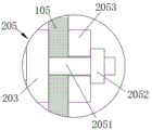
FIG. 2 is a schematic view of a positioning and clamping mechanism according to the present utility model;
FIG. 3 is a schematic view of a clamping assembly according to the present utility model;
FIG. 4 is a schematic view of the structure of the adjusting assembly of the present utility model;
in the figure: 100. a tester main body; 101. a vertical frame; 102. a cross frame; 103. a chuck; 104. an operation box; 105. a cloth sample; 200. positioning and clamping mechanisms; 201. installing a positioning plate; 202. countersunk nails; 203. a fixing plate; 204. a support rod; 205. a clamping assembly; 2051. fixing the column; 2052. a limiting ring; 2053. a clamping plate; 300. an adjustment assembly; 301. a mounting frame; 302. a vertical rail; 303. and a sliding sleeve.
Detailed Description
The following description of the embodiments of the present utility model will be made clearly and completely with reference to the accompanying drawings, in which it is apparent that the embodiments described are only some embodiments of the present utility model, but not all embodiments. All other embodiments, which can be made by those skilled in the art based on the embodiments of the utility model without making any inventive effort, are intended to be within the scope of the utility model.
Referring to fig. 1-4, the present utility model provides a technical solution: the utility model provides a tensile tester, including tester main part 100 and location fixture 200, the tester main part 100 includes cross frame 102, chuck 103 and cloth sample 105, two chucks 103 are installed on tester main part 100 and cross frame 102 surface relatively, cloth sample 105 centre gripping is between two chucks 103, can press from both sides tight and tensile test to cloth sample 105, location fixture 200 installs between chuck 103 and cloth sample 105, location fixture 200 can carry out spacingly to the cloth sample 105 of centre gripping, further increase cloth sample 105 centre gripping tightness simultaneously, location fixture 200 includes installation locating plate 201, countersunk head nail 202, fixed plate 203, bracing piece 204 and clamping assembly 205, installation locating plate 201 passes through countersunk head nail 202 to be fixed at chuck 103 surface, and the scale mark has been seted up on installation locating plate 201 surface, the scale mark can be fixed to the cloth sample 105 tip position of being held, fixed plate 203 passes through bracing piece 204 to be fixed at installation locating plate 201 upper surface, cloth sample 105 is located between fixed plate 203 and the clamping assembly 205, further carry out the clamp fixing to cloth sample 105.
In this embodiment, preferably, the clamping assembly 205 includes a fixing column 2051, a limiting ring 2052 and a clamping plate 2053, the clamping assembly 205 can be matched with the fixing plate 203, further clamp and fix the cloth sample 105, the clamping tightness of the cloth sample 105 is increased, the clamping plate 2053 is located on the right side of the cloth sample 105, rectangular holes for the fixing column 2051 to extend in are formed in the front end and the rear end of the clamping plate 2053, the left end of the fixing column 2051 is fixed on the right side of the fixing plate 203, the right end of the fixing column 2051 is exposed outside in the rectangular holes, the limiting ring 2052 is sleeved at the end of the fixing column 2051 in a screwing mode, the limiting ring 2052 contacts and limits the right side surface of the clamping plate 2053, the limiting ring 2052 can fix the position of the clamping plate 2053, and the clamping tightness of the clamping plate 2053 and the fixing plate 203 to the cloth sample 105 is increased.
In this embodiment, preferably, the support rod 204 is L-shaped, the lower end of the support rod 204 is fixed on the upper surface of the mounting and positioning plate 201, which can support the fixing plate 203, and the upper end of the support rod 204 is fixed on the left side of the fixing plate 203.
In this embodiment, preferably, the upper surface of the tester main body 100 is provided with the stand 101, the front surface of the stand 101 is provided with the operation box 104, and an adjusting component 300 is arranged between the stand 101 and the operation box, the adjusting component 300 comprises a mounting rack 301, a vertical rail 302 and a sliding sleeve 303, the adjusting component 300 can change the height position of the operation box 104, the convenience of operation of the operation box 104 is improved, the mounting rack 301 is fixed on the right side of the stand 101 through screws, the mounting rack 301 is convenient to assemble and disassemble subsequently, the vertical rail 302 is vertically fixed on the front surface of the mounting rack 301, the sliding sleeve 303 is fixed on the rear surface of the operation box 104 and is sleeved on the vertical rail 302 in a sliding manner, the sliding sleeve 303 can move along the vertical rail 302 to drive the operation box 104 to move to change the operation height, a rubber sheet is arranged on the inner surface of the sliding sleeve 303, and the rubber sheet can increase the frictional resistance with the vertical rail 302 until now, so that the sliding sleeve 303 is not easy to move under the condition that no external force is applied.
In this embodiment, preferably, the cross frame 102 is horizontally and slidably mounted in the stand 101, the cross frame 102 is movable and adjustable up and down, and a connection line is provided between the operation box 104 and the stand 101.
The working principle and the using flow of the utility model are as follows: when the tester is used, the positioning and clamping mechanism 200 is fixed on the surface of the clamping heads 103 through the countersunk nails 202, the cloth sample 105 is clamped between the two clamping heads 103, meanwhile, the clamping lengths of the end parts of the cloth sample 105 in the clamping heads 103 are consistent, the clamping tightness of the two clamping heads is improved, the condition that the length of one end is uncomfortable and is separated is avoided, meanwhile, the clamping plate 2053 is positioned on the outer side of the fixing plate 203, the cloth sample 105 is positioned between the two clamping heads, the fixing column 2051 is positioned in a rectangular notch, the limiting ring 2052 is tightly screwed to tightly press the clamping plate 2053, the clamping plate 2053 and the fixing plate 203 further fixedly clamp the cloth sample 105, the probability of separating the cloth sample 105 from the clamping heads 103 is reduced, the tension test stability and safety of the cloth sample 105 are improved, and the clamping heads 103 on the transverse frame 102 can move upwards along with the operation of the whole tester main body 100, and the cloth sample 105 is stretched for tension test.
Although embodiments of the present utility model have been shown and described in detail with reference to the foregoing detailed description, it will be understood by those skilled in the art that various changes, modifications, substitutions and alterations may be made therein without departing from the principles and spirit of the utility model, the scope of which is defined in the appended claims and their equivalents.
Claims (7)
1. The utility model provides a tensile tester, includes tester main part (100) and location fixture (200), tester main part (100) include crossbearer (102), chuck (103) and cloth sample (105), two chuck (103) are installed relatively on tester main part (100) and crossbearer (102) surface, cloth sample (105) centre gripping is between two chucks (103), its characterized in that: the utility model provides a cloth sample, including fixing a clamp head (103), cloth sample (105) is fixed to location fixture (200), location fixture (200) is installed between clamp head (103) and cloth sample (105), location fixture (200) is including installation locating plate (201), countersunk head nail (202), fixed plate (203), bracing piece (204) and clamping assembly (205), installation locating plate (201) are fixed on clamp head (103) surface through countersunk head nail (202), just the scale mark has been seted up on installation locating plate (201) surface, fixed plate (203) are fixed at installation locating plate (201) upper surface through bracing piece (204), cloth sample (105) are located between fixed plate (203) and clamping assembly (205).
2. The tensile tester of claim 1, wherein: clamping assembly (205) are including fixed column (2051), spacing ring (2052) and grip block (2053), grip block (2053) are located cloth sample (105) right side, just rectangular hole that supplies fixed column (2051) to stretch into has all been seted up to grip block (2053) front and back end, fixed column (2051) left end is fixed on fixed plate (203) right side, fixed column (2051) right-hand member is located rectangular hole and exposes in the outside.
3. A tensile tester according to claim 2, wherein: the limiting ring (2052) is sleeved at the end part of the fixed column (2051) in a screwing mode, and the limiting ring (2052) is in contact limiting with the right side face of the clamping plate (2053).
4. The tensile tester of claim 1, wherein: the support rod (204) is L-shaped, the lower end of the support rod (204) is fixed on the upper surface of the installation positioning plate (201), and the upper end of the support rod (204) is fixed on the left side of the fixing plate (203).
5. The tensile tester of claim 1, wherein: the tester is characterized in that a stand (101) is arranged on the upper surface of the tester body (100), an operation box (104) is arranged on the front surface of the stand (101), an adjusting component (300) is arranged between the stand and the operation box, the adjusting component (300) comprises a mounting frame (301), a vertical rail (302) and a sliding sleeve (303), the mounting frame (301) is fixed on the right side of the stand (101) through screws, and the vertical rail (302) is vertically fixed on the front surface of the mounting frame (301).
6. The tensile tester of claim 5, wherein: the sliding sleeve (303) is fixed on the rear surface of the operation box (104) and is sleeved on the vertical rail (302) in a sliding manner, and a rubber sheet is arranged on the inner surface of the sliding sleeve (303).
7. The tensile tester of claim 5, wherein: the transverse frame (102) is horizontally and slidably arranged in the vertical frame (101), and a connecting line is arranged between the operation box (104) and the vertical frame (101).
Priority Applications (1)
| Application Number | Priority Date | Filing Date | Title |
|---|---|---|---|
| CN202222662296.6U CN219201125U (en) | 2022-10-10 | 2022-10-10 | Tension tester |
Applications Claiming Priority (1)
| Application Number | Priority Date | Filing Date | Title |
|---|---|---|---|
| CN202222662296.6U CN219201125U (en) | 2022-10-10 | 2022-10-10 | Tension tester |
Publications (1)
| Publication Number | Publication Date |
|---|---|
| CN219201125U true CN219201125U (en) | 2023-06-16 |
Family
ID=86720395
Family Applications (1)
| Application Number | Title | Priority Date | Filing Date |
|---|---|---|---|
| CN202222662296.6U Active CN219201125U (en) | 2022-10-10 | 2022-10-10 | Tension tester |
Country Status (1)
| Country | Link |
|---|---|
| CN (1) | CN219201125U (en) |
-
2022
- 2022-10-10 CN CN202222662296.6U patent/CN219201125U/en active Active
Similar Documents
| Publication | Publication Date | Title |
|---|---|---|
| CN219201125U (en) | Tension tester | |
| CN218765062U (en) | Finished product quality detection device is used in concrete pole production | |
| CN217006182U (en) | Suture tension detection device | |
| CN109269888A (en) | A kind of fixture stretched for detection cable insulation | |
| CN204944947U (en) | A kind of mica tape tensile strength test device | |
| CN210572410U (en) | Automatic function test fixture | |
| CN208476153U (en) | A kind of machine for rolling parts cubing | |
| CN211955018U (en) | Electronic strength tester | |
| CN208383680U (en) | A kind of detection ABS gear ring pulling-out force test tool | |
| CN220136839U (en) | Cloth stretching detection device | |
| CN215339299U (en) | Building new material detection device | |
| CN217424690U (en) | Sample rigidity testing device | |
| CN210269410U (en) | Device for detecting pulling-out force of hot-buried screw | |
| CN211740034U (en) | Quick detection mechanism of return bend resilience precision | |
| CN213301016U (en) | Vehicle side door C post sub-assembly inspection jig | |
| CN211361951U (en) | Positioning device for automobile framework | |
| CN216593850U (en) | Connecting frame and color temperature testing assembly adopting same | |
| CN218066196U (en) | Automobile shock absorber examines utensil | |
| CN220206579U (en) | Finished product inspection device of torsion Liang Gongjian | |
| CN215296624U (en) | Detection device for detecting automobile skylight wire clamp | |
| CN219444874U (en) | Portable high-precision area array light source clamp | |
| CN220438523U (en) | LED lamp tube test board | |
| CN220650305U (en) | Tensile force testing device of high-strength lamp box cloth | |
| CN217211844U (en) | Fatigue life testing device for reaction rod support | |
| CN211927554U (en) | Riveting strength tensile test device |
Legal Events
| Date | Code | Title | Description |
|---|---|---|---|
| GR01 | Patent grant | ||
| GR01 | Patent grant |