CN219193659U - Automatic runner device of cutting of laser - Google Patents
Automatic runner device of cutting of laser Download PDFInfo
- Publication number
- CN219193659U CN219193659U CN202223405801.5U CN202223405801U CN219193659U CN 219193659 U CN219193659 U CN 219193659U CN 202223405801 U CN202223405801 U CN 202223405801U CN 219193659 U CN219193659 U CN 219193659U
- Authority
- CN
- China
- Prior art keywords
- laser
- pushing
- working platform
- sliding block
- material taking
- Prior art date
- Legal status (The legal status is an assumption and is not a legal conclusion. Google has not performed a legal analysis and makes no representation as to the accuracy of the status listed.)
- Active
Links
Images


Classifications
-
- Y—GENERAL TAGGING OF NEW TECHNOLOGICAL DEVELOPMENTS; GENERAL TAGGING OF CROSS-SECTIONAL TECHNOLOGIES SPANNING OVER SEVERAL SECTIONS OF THE IPC; TECHNICAL SUBJECTS COVERED BY FORMER USPC CROSS-REFERENCE ART COLLECTIONS [XRACs] AND DIGESTS
- Y02—TECHNOLOGIES OR APPLICATIONS FOR MITIGATION OR ADAPTATION AGAINST CLIMATE CHANGE
- Y02P—CLIMATE CHANGE MITIGATION TECHNOLOGIES IN THE PRODUCTION OR PROCESSING OF GOODS
- Y02P70/00—Climate change mitigation technologies in the production process for final industrial or consumer products
- Y02P70/10—Greenhouse gas [GHG] capture, material saving, heat recovery or other energy efficient measures, e.g. motor control, characterised by manufacturing processes, e.g. for rolling metal or metal working
Landscapes
- Laser Beam Processing (AREA)
Abstract
The utility model discloses an automatic pouring gate cutting device of laser, which comprises a working platform, wherein a laser punching machine is arranged on the working platform, a pushing mechanism is arranged on the working platform below the laser punching machine, a positioning jig is arranged on the pushing mechanism, a product positioning groove is processed on the surface of the positioning jig, a pouring gate material box is arranged on the pushing mechanism, a pouring gate material taking mechanism is arranged on the working platform between the pouring gate material box and the laser punching machine, a belt conveyor is arranged at the other end of the pushing mechanism, and a product blanking manipulator is arranged between the belt conveyor and the laser punching machine. The device improves the production efficiency, improves the punching precision of products, has higher automation degree and low cost for subsequent use and maintenance, can meet the punching requirements of MIM products with different structures, and has stronger practicability.
Description
Technical Field
The utility model belongs to the technical field of metal powder processing, and particularly relates to an automatic gate cutting device for laser.
Background
The metal powder injection molding (MIM) technology is a novel near-net molding technology. The method is a product integrating multiple subjects such as plastic injection molding technology, polymer chemistry, powder metallurgy technology, metal material technology and the like and penetrating and crossing each other, a blank can be injection molded by utilizing a die and structural parts with high density, high precision, high strength and three-dimensional complex shapes are quickly manufactured through sintering, especially small parts with complex shapes which are processed or are difficult to process by utilizing technological methods such as mechanical processing and the like, MIM technology can be freely completed, and the method has the advantages of low cost, high efficiency, good consistency and the like, is easy to form mass production, and is known as the most popular part molding technology at present. In the process of metal powder injection molding, in order to improve the production efficiency, most MIM products with smaller structures can be subjected to the structure of more than two products in one casting mold, 4 MIM products in fig. 4-5 are cast in the casting mold during casting, pouring channels are formed between the products for the convenience of casting, and after the products are subjected to injection molding, the processes of pouring channel punching, hole separation dishing, gate repairing and the like are needed. In the prior art, the punching mode of the traditional machine is adopted when the pouring gate and the product are punched in most cases, the punching mode is low in punching efficiency, low in punching precision and high in maintenance cost, the product pouring gate is required to be trimmed after punching, in addition, the cutter is severely worn in the mechanical punching process, and the cutter is required to be replaced frequently. Therefore, the development of the laser automatic gate cutting device with high automation degree, high punching efficiency, high punching precision, strong practicability and low maintenance cost is objectively needed.
Disclosure of Invention
The utility model aims to provide the laser automatic gate cutting device which has the advantages of high automation degree, high punching efficiency, high punching precision, strong practicability and low maintenance cost.
The utility model aims at realizing the technical scheme that the laser blanking machine comprises a working platform, wherein the working platform is provided with a laser blanking machine, the laser blanking machine comprises a supporting frame and a laser generator, a lifting assembly is arranged at the top of the supporting frame, the laser generator is arranged below the lifting assembly through a connecting plate, a laser blanking head is arranged at the output end of the laser generator, the working platform below the laser blanking machine is provided with a pushing mechanism, the pushing mechanism is provided with a positioning jig, the surface of the positioning jig is provided with a product positioning groove, the pushing mechanism is provided with a pouring gate material box, the working platform between the pouring gate material box and the laser blanking machine is provided with a pouring gate material taking mechanism, the other end of the pushing mechanism is provided with a belt conveyor, and a product blanking manipulator is arranged between the belt conveyor and the laser blanking machine.
In this device, the automatic punching of between to a plurality of MIM products and its connection runner has been saved to the laser die-cut machine that sets up, has saved the process of repairing the runner, just can die-cut shaping once, not only effectually improved die-cut efficiency, and improved die-cut precision moreover, the pushing equipment that sets up can convey the MIM product that carries positioning jig between laser die-cut machine and product unloading manipulator, realize automatic feeding, the material taking mechanism that sets up can shift the runner of die-cut unloading to in the runner magazine, the product unloading manipulator that sets up can shift the MIM product after the die-cut to band conveyer. Compared with the mechanical punching mode of transmission, the device has the advantages that: firstly, the die-cut molding can be carried out once, the procedure of trimming a gate is omitted, the production efficiency is improved, the die-cut precision of products is improved, secondly, the automatic feeding of products before die-cut, the automatic discharging of pouring channels and the automatic discharging of products after die-cut can be realized, the whole process does not need to be manually participated, and the degree of automation is higher; thirdly, the laser punching machine has no cutter abrasion phenomenon in the using process, and the subsequent use and maintenance cost is low; fourthly, the positioning jig adopts the pushing mechanism to carry out the transmission, and easy the change can be according to the positioning jig of the different structures of shape change of MIM product to satisfy the die-cut demand of the MIM product of different structures, its practicality is stronger, has better popularization and utilization value.
Drawings
FIG. 1 is a top view of the present utility model;
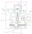
FIG. 2 is view A-A of FIG. 1T;
FIG. 3 is a top view of a pre-compression form 61 of the present utility model;
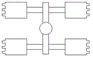
fig. 4 is a top view of a MIM product according to the present utility model;
fig. 5 is a front view of a MIM product according to the present utility model;
in the figure: the device comprises a 1-working platform, a 2-laser punching machine, a 21-supporting frame, a 22-laser generator, a 23-lifting component, a 24-laser punching head, a 3-pushing mechanism, a 31-pushing screw, a 32-pushing motor, a 33-pushing slide seat, a 34-base, a 35-guide rod, a 4-positioning jig, a 41-product positioning groove, a 5-pouring box, a 6-pouring taking mechanism, a 61-pre-pressing template, a 62-first jacking cylinder, a 63-second jacking cylinder, a 64-taking groove, a 65-taking plate, a 66-pneumatic suction nozzle, a 67-first sliding rail, a 68-second sliding rail, a 69-first sliding block, a 610-second sliding block, a 611-first positioning plate, a 612-second positioning plate, a 7-belt conveyor, an 8-product blanking manipulator, a 9-receiving jig and a 10-feeding manipulator.
Description of the embodiments
The utility model is further described below with reference to the accompanying drawings, without limiting the utility model in any way, and any alterations or modifications based on the teachings of the utility model are within the scope of the utility model.
As shown in fig. 1 to 5, the utility model comprises a working platform 1, a laser punching machine 2 is arranged on the working platform 1, the laser punching machine 2 comprises a supporting frame 21 and a laser generator 22, a lifting component 23 is arranged at the top of the supporting frame 21, the laser generator 22 is arranged below the lifting component 23 through a connecting plate, a laser punching head 24 is arranged at the output end of the laser generator 22, the structures of the laser generator 22 and the laser punching head 24 adopt the structures in the prior art, the principle of which is not illustrated herein, the laser punching head 24 uses the laser beam generated by the laser emitter 23 to punch MIM products and pouring channels connected with the MIM products, the punching of the pouring channels can be completed once, the pouring channel surfaces of the punched products are smooth and even without secondary trimming, a pushing mechanism 3 is arranged on the working platform 1 below the laser punching machine 2, the pushing mechanism 3 is provided with a positioning jig 4, the surface of the positioning jig 4 is provided with a product positioning groove 41, the positioning jig 4 is arranged on the pushing mechanism 3, when the pushing mechanism is used, the positioning jig 4 is reasonably replaced according to the connection structure of MIM products and pouring channels, so as to meet the requirement that one device can punch MIM products with various structures, the investment of equipment cost can be saved to a certain extent, the pushing mechanism 3 is provided with a pouring channel material box 5, the pouring channel material box 5 is used for storing pouring channels for blanking, the working platform 1 between the pouring channel material box 5 and the laser punching machine 2 is provided with a pouring channel material taking mechanism 6, the pouring channel material taking mechanism 6 is used for shifting the pouring channels which are punched and cut out from the positioning jig 4 into the pouring channel material box 5, the other end of the pushing mechanism 3 is provided with a belt conveyor 7, the belt conveyor 7 is of a structure used in the prior art, be used for carrying the MIM product after die-cut, be provided with product unloading manipulator 8 between band conveyer 7 and the laser die-cut machine 2, product unloading manipulator 8 adopts the structure that uses among the prior art, only can from the location tool 4 with the MIM product after die-cut once only shift to band conveyer on.
The working process of the device is as follows: and placing the injection molded MIM product with the pouring gate into a product positioning groove 41 of a positioning jig 4, pushing the positioning jig 4 to the lower part of a laser punching machine 2 by a pushing mechanism 3, punching the pouring gate connected with the MIM product by the laser punching machine 2, realizing punching separation of the pouring gate and the MIM product, then shifting the MIM product after punching blanking into a pouring gate material box 5 by a pouring gate material taking manipulator 6, returning to the original position by the pushing mechanism 3, shifting the MIM product after punching separation onto a belt conveyor 7 by a product blanking manipulator 8, and conveying the MIM product to a subsequent process by the belt conveyor 7. Compared with the mechanical punching mode of transmission, the device has the advantages that: firstly, the die-cut molding can be carried out once, the procedure of trimming a gate is omitted, the production efficiency is improved, the die-cut precision of products is improved, secondly, the automatic feeding of products before die-cut, the automatic discharging of pouring channels and the automatic discharging of products after die-cut can be realized, the whole process does not need to be manually participated, and the degree of automation is higher; thirdly, the laser punching machine 2 has no cutter abrasion phenomenon in the using process, and the subsequent use and maintenance costs are low; fourthly, the positioning jig 4 adopts the pushing mechanism 3 to carry out the transmission, and easy the change can be according to the positioning jig 4 of MIM product's shape change different structures to satisfy the die-cut demand of MIM product of different structures, its practicality is stronger.
Further, in order to improve the continuity of production, be provided with on the work platform 1 of pushing equipment 3 one side and connect material tool 9, be provided with product constant head tank 41 on the surface of connecing material tool 9, work platform 1's one side install with connect material tool 9 assorted material loading manipulator 10, material loading manipulator 10 will need the MIM product of die-cut shift to connect material tool 9 on, product unloading manipulator 8 just can shift the MIM product to on the positioning jig 4, just so can realize the die-cut continuity of MIM product.
Further, the pushing mechanism 3 includes a pushing screw 31, a pushing motor 32 and a pushing slide 33, the pushing motor 32 is in the prior art, according to the used power, two bases 34 are installed on the working platform 1 between the laser blanking machine 2 and the belt conveyor 7 at intervals, threaded holes are formed in the pushing slide 33 in a penetrating manner, the pushing screw 31 is installed in the threaded holes, two ends of the pushing screw 31 are rotatably installed between the two bases 34, the pushing motor 32 is installed on the outer side of one base 34 and is in transmission connection with one end of the pushing screw 31, and when the working principle of the pushing mechanism 3 is as follows: the pushing motor 32 drives the pushing screw 31 to rotate, and the pushing slide seat 33 can reciprocate along the pushing screw 31 in the rotating process of the pushing screw 31, so that the positioning jig 4 can be reset between the laser punching machine 2 and the belt conveyor 7. Preferably, in order to ensure the stability of the pushing slide 33 in the reciprocating movement process, guide holes are formed in the pushing slide 33 on both sides of the pushing screw 31 in a penetrating manner, a guide rod 35 is slidably mounted in the guide holes, the guide rod 35 is fixedly mounted between the two bases 34, the guide rod 35 can play a guiding role, and the pushing slide 33 can be ensured to reciprocate linearly along the pushing screw 31.
Further, the pouring gate material taking mechanism 6 comprises a translation module and a pre-pressing template 61, the translation module is installed on the working platform 1, two first jacking air cylinders 62 and second jacking air cylinders 63 are symmetrically installed on the translation module, the first jacking air cylinders 62 and the second jacking air cylinders 63 adopt structures in the prior art, finished products are directly purchased according to the used pressure, stroke and other technical parameters, the pre-pressing template 61 is installed at the upper ends of the first jacking air cylinders 62 and the second jacking air cylinders 63, a material taking groove 64 is formed in the pre-pressing template 61, the size of the material taking groove 64 is smaller than that of the product positioning groove 41, only the edge of the pre-pressing template 61 can be pressed by the edge of a product, a material taking plate 65 is parallelly installed on the upper side of the pre-pressing template 61, a plurality of pneumatic suction nozzles 66 are arranged on the lower side of the material taking plate 65, and the plurality of pneumatic suction nozzles 66 are located in the material taking groove 64. The working principle of the pouring gate material taking mechanism 6 is as follows: when the positioning jig 4 is pushed to the lower part of the laser blanking machine 2, the translation module drives the first jacking air cylinder 62, the second jacking air cylinder 63 and the pre-pressing template 61 to move, when the translation module moves to the upper part of the positioning jig 4, the first jacking air cylinder 62, the second jacking air cylinder 63 drive the pre-pressing template 61 to move downwards, when the translation module moves to the pre-pressing template 61 to press MIM products on the positioning jig 4, the first jacking air cylinder 62 and the second jacking air cylinder 63 stop acting, the laser blanking machine 2 performs blanking on MIM products and pouring channels, after the blanking is completed, the pneumatic suction nozzle 66 sucks the blanked pouring channels, the first jacking air cylinder 62 and the second jacking air cylinder 63 drive the pre-pressing template 61 to move upwards, the pre-pressing template 61 is separated from the blanked MIM products, at this time, the translation module drives the first jacking air cylinder 62, the second jacking air cylinder 63 and the pre-pressing template 61 to move towards the direction of the pouring channel material box 5, when the translation module moves to the upper part of the pouring channel material box 5, the pneumatic 66 can shift the pouring channels into the product material box 5, and the products after the blanking is stopped in the positioning jig 4 are shifted by the mechanical suction nozzle 8.
The translation module can adopt rack and pinion transmission, screw rod slider drive mechanism that use among the prior art, preferably, the translation module includes drive assembly, first slide rail 67 and second slide rail 68 parallel arrangement are on the work platform 1 of runner magazine 5 both sides, slidable mounting has first slider 69 on the first slide rail 67, slidable mounting has second slider 610 on the second slide rail 68, and first slider 69 and second slider 610 correspond the setting, install first locating plate 611 perpendicularly on the first slider 69, install second locating plate 612 on the first slider 69, first jacking cylinder 62 is installed on first locating plate 611, second jacking cylinder 63 is installed on second locating plate 612, drive assembly is connected with first slider 69 or second slider 610 transmission. The driving assembly is of a driving cylinder structure. When the device is used, the driving cylinder pushes the sliding block connected with the driving cylinder to move, and the sliding block can drive the first jacking cylinder 62 and the second jacking cylinder 63 to synchronously move along the first sliding rail 67 and the second sliding rail 68 respectively in the moving process, so that the synchronous movement of the pre-pressing template 61 and the pneumatic suction nozzle 66 can be realized.
Claims (7)
1. The utility model provides an automatic runner device of cutting of laser, includes work platform (1), its characterized in that: be provided with laser die-cut machine (2) on work platform (1), laser die-cut machine (2) include support frame (21) and laser generator (22), lifting unit (23) are installed at the top of support frame (21), laser generator (22) are installed in the below of lifting unit (23) through the connecting plate, laser punching head (24) are installed to the output of laser generator (22), be provided with pushing equipment (3) on work platform (1) of laser die-cut machine (2) below, install location tool (4) on pushing equipment (3), processing has product constant head tank (41) on the surface of location tool (4), be provided with on pushing equipment (3) and water magazine (5), be provided with on work platform (1) between pouring magazine (5) and laser die-cut machine (2) and water mechanism (6), the other end of pushing equipment (3) is provided with band conveyer (7), be provided with between band conveyer (7) and laser die-cut machine (8) and take out mechanical hand.
2. The laser automatic gating apparatus of claim 1, wherein: the feeding device comprises a working platform (1) on one side of a pushing mechanism (3), a receiving jig (9) is arranged on the working platform, a product positioning groove (41) is formed in the surface of the receiving jig (9), and a feeding manipulator (10) matched with the receiving jig (9) is arranged on one side of the working platform (1).
3. The laser automatic gating apparatus of claim 1, wherein: the pushing mechanism (3) comprises a pushing screw (31), a pushing motor (32) and a pushing sliding seat (33), two bases (34) are installed on a working platform (1) between the laser punching machine (2) and the belt conveyor (7) at intervals, threaded holes are formed in the pushing sliding seat (33) in a penetrating mode, the pushing screw (31) is installed in the threaded holes, two ends of the pushing screw (31) are rotatably installed between the two bases (34), and the pushing motor (32) is installed on the outer side of one base (34) and is in transmission connection with one end of the pushing screw (31).
4. A laser automatic gating apparatus according to claim 3, wherein: the pushing slide seat (33) on two sides of the pushing screw rod (31) is provided with a guide hole in a penetrating mode, a guide rod (35) is slidably arranged in the guide hole, and the guide rod (35) is fixedly arranged between the two bases (34).
5. The laser automatic gating apparatus of claim 1, wherein: the pouring gate material taking mechanism (6) comprises a translation module and a pre-pressing template (61), wherein the translation module is arranged on a working platform (1), two first jacking cylinders (62) and second jacking cylinders (63) are symmetrically arranged on the translation module, the pre-pressing template (61) is arranged at the upper ends of the first jacking cylinders (62) and the second jacking cylinders (63), a material taking groove (64) is formed in the pre-pressing template (61), the size of the material taking groove (64) is smaller than that of a product positioning groove (41), a material taking plate (65) is arranged on the upper side of the pre-pressing template (61) in parallel, a plurality of pneumatic suction nozzles (66) are arranged on the lower side of the material taking plate (65), and the pneumatic suction nozzles (66) are located in the material taking groove (64).
6. The laser automatic gating apparatus of claim 5, wherein: the translation module comprises a driving assembly, a first sliding rail (67) and a second sliding rail (68), wherein the first sliding rail (67) and the second sliding rail (68) are arranged on a working platform (1) on two sides of a pouring gate material box (5) in parallel, a first sliding block (69) is arranged on the first sliding rail (67) in a sliding mode, a second sliding block (610) is arranged on the second sliding rail (68) in a sliding mode, the first sliding block (69) and the second sliding block (610) are correspondingly arranged, a first positioning plate (611) is vertically arranged on the first sliding block (69), a second positioning plate (612) is arranged on the first sliding block (69), a first jacking cylinder (62) is arranged on the first positioning plate (611), and the second jacking cylinder (63) is arranged on the second positioning plate (612) in a transmission mode, and the driving assembly is connected with the first sliding block (69) or the second sliding block (610).
7. The laser automatic gating apparatus of claim 6, wherein: the driving assembly is of a driving cylinder structure.
Priority Applications (1)
| Application Number | Priority Date | Filing Date | Title |
|---|---|---|---|
| CN202223405801.5U CN219193659U (en) | 2022-12-20 | 2022-12-20 | Automatic runner device of cutting of laser |
Applications Claiming Priority (1)
| Application Number | Priority Date | Filing Date | Title |
|---|---|---|---|
| CN202223405801.5U CN219193659U (en) | 2022-12-20 | 2022-12-20 | Automatic runner device of cutting of laser |
Publications (1)
| Publication Number | Publication Date |
|---|---|
| CN219193659U true CN219193659U (en) | 2023-06-16 |
Family
ID=86703630
Family Applications (1)
| Application Number | Title | Priority Date | Filing Date |
|---|---|---|---|
| CN202223405801.5U Active CN219193659U (en) | 2022-12-20 | 2022-12-20 | Automatic runner device of cutting of laser |
Country Status (1)
| Country | Link |
|---|---|
| CN (1) | CN219193659U (en) |
Cited By (1)
| Publication number | Priority date | Publication date | Assignee | Title |
|---|---|---|---|---|
| CN118002940A (en) * | 2024-04-08 | 2024-05-10 | 信丰六一节能科技有限公司 | Slitter edge cutting device is used in plastic part processing |
-
2022
- 2022-12-20 CN CN202223405801.5U patent/CN219193659U/en active Active
Cited By (1)
| Publication number | Priority date | Publication date | Assignee | Title |
|---|---|---|---|---|
| CN118002940A (en) * | 2024-04-08 | 2024-05-10 | 信丰六一节能科技有限公司 | Slitter edge cutting device is used in plastic part processing |
Similar Documents
| Publication | Publication Date | Title |
|---|---|---|
| KR20190088514A (en) | Hydraulic molding machine and metal ball molding machine | |
| CN219193659U (en) | Automatic runner device of cutting of laser | |
| CN219468099U (en) | Automatic swaying disc device for MIM (metal-insulator-metal) products | |
| CN213256598U (en) | Integrated processing device for impeller blade of hydraulic torque converter | |
| CN211721673U (en) | Wonton forming device | |
| CN111571285A (en) | Positioning plate feeding and punching integrated equipment for mold machining | |
| CN216828253U (en) | L-shaped punching, arc-cutting and cutting composite die | |
| CN213827016U (en) | Multifunctional automatic shaping hydraulic press for powder metallurgy | |
| CN205732449U (en) | A kind of auto parts machinery fast hydraulic pressure punch press | |
| CN214446725U (en) | Precision mold for machining multiple parts | |
| CN111545691B (en) | Semi-open type metal elastic part forming equipment and forming method thereof | |
| CN112355308A (en) | Multifunctional automatic shaping hydraulic press for powder metallurgy | |
| CN221312057U (en) | Stamping forming device for die machining | |
| CN207899978U (en) | The continuously shaped equipment of multistation metal | |
| CN217123864U (en) | Automatic punching device for injection molding pouring gate | |
| CN217047344U (en) | Die-cut back even mouth of a river die-cut equipment in incision | |
| CN206997463U (en) | Gusset fine blanking die | |
| CN219188300U (en) | Automatic punching device for continuous material of MIM (metal-insulator-metal) product | |
| CN217167427U (en) | Retreat and cut-off device suitable for lace door frame production | |
| CN219052593U (en) | Kovar ring stamping die | |
| CN214981552U (en) | Double-mold reinforcing device | |
| CN220311459U (en) | Die-cut frock of pivot supporting rib | |
| CN116079056A (en) | Full-automatic processing device for MIM (metal-insulator-metal) product multi-gate surface | |
| CN218049841U (en) | Automatic stamping equipment who tailors | |
| CN220264318U (en) | Automatic pushing mechanism |
Legal Events
| Date | Code | Title | Description |
|---|---|---|---|
| GR01 | Patent grant | ||
| GR01 | Patent grant |