CN214981552U - Double-mold reinforcing device - Google Patents
Double-mold reinforcing device Download PDFInfo
- Publication number
- CN214981552U CN214981552U CN202121162952.5U CN202121162952U CN214981552U CN 214981552 U CN214981552 U CN 214981552U CN 202121162952 U CN202121162952 U CN 202121162952U CN 214981552 U CN214981552 U CN 214981552U
- Authority
- CN
- China
- Prior art keywords
- plate
- fixedly connected
- cylinder
- die
- pulling
- Prior art date
- Legal status (The legal status is an assumption and is not a legal conclusion. Google has not performed a legal analysis and makes no representation as to the accuracy of the status listed.)
- Active
Links
- 230000003014 reinforcing effect Effects 0.000 title claims abstract description 15
- 239000000463 material Substances 0.000 claims abstract description 123
- 230000007246 mechanism Effects 0.000 claims abstract description 23
- 230000002787 reinforcement Effects 0.000 claims abstract description 19
- 238000004080 punching Methods 0.000 claims abstract description 18
- 238000000034 method Methods 0.000 claims abstract description 6
- 230000008569 process Effects 0.000 claims abstract description 4
- 238000003825 pressing Methods 0.000 claims description 39
- 239000002699 waste material Substances 0.000 claims description 31
- 230000009977 dual effect Effects 0.000 claims description 6
- 230000000712 assembly Effects 0.000 claims description 3
- 238000000429 assembly Methods 0.000 claims description 3
- 239000012779 reinforcing material Substances 0.000 claims description 3
- 230000006872 improvement Effects 0.000 description 3
- 238000007599 discharging Methods 0.000 description 2
- 238000001125 extrusion Methods 0.000 description 2
- 238000005242 forging Methods 0.000 description 2
- 238000001746 injection moulding Methods 0.000 description 2
- 238000004519 manufacturing process Methods 0.000 description 2
- 230000004048 modification Effects 0.000 description 2
- 238000012986 modification Methods 0.000 description 2
- 239000000243 solution Substances 0.000 description 2
- 241000251468 Actinopterygii Species 0.000 description 1
- 238000003723 Smelting Methods 0.000 description 1
- 230000009471 action Effects 0.000 description 1
- 230000009286 beneficial effect Effects 0.000 description 1
- 238000000071 blow moulding Methods 0.000 description 1
- 238000005266 casting Methods 0.000 description 1
- 239000000919 ceramic Substances 0.000 description 1
- 230000008859 change Effects 0.000 description 1
- 238000000748 compression moulding Methods 0.000 description 1
- 238000005336 cracking Methods 0.000 description 1
- 238000005520 cutting process Methods 0.000 description 1
- 238000004512 die casting Methods 0.000 description 1
- 229920006351 engineering plastic Polymers 0.000 description 1
- 238000009776 industrial production Methods 0.000 description 1
- 238000004663 powder metallurgy Methods 0.000 description 1
- 239000005060 rubber Substances 0.000 description 1
- 238000006748 scratching Methods 0.000 description 1
- 230000002393 scratching effect Effects 0.000 description 1
- 230000003746 surface roughness Effects 0.000 description 1
Images

Landscapes
- Perforating, Stamping-Out Or Severing By Means Other Than Cutting (AREA)
Abstract
The utility model provides a double-mold reinforcing device, which belongs to the technical field of molds and comprises a lower cylinder seat, wherein the lower inner wall of the lower cylinder seat is fixedly connected with a lower cylinder, the upper end of the lower cylinder seat is fixedly connected with a mounting plate through two connecting plates, and the side end of the lower cylinder seat is fixedly connected with a movable plate; the reinforcing mechanism comprises a clamping component and a blade component, and the clamping component and the blade component are both arranged on the lower side of the mounting plate to realize material reinforcement; the two sets of die mechanisms are connected with the movable plate to realize punching operation of materials; and the receiving mechanism is arranged on the upper side of the mounting plate to realize a reinforcing receiving process, the material is filled into the receiving mechanism to improve the strength of the material, and the loss of the material in the punching operation is reduced.
Description
Technical Field
The utility model belongs to the technical field of the mould, concretely relates to bimodulus utensil reinforcement device.
Background
The mould is various moulds and tools for obtaining required products by injection molding, blow molding, extrusion, die casting or forging forming, smelting, stamping and other methods in industrial production. In short, a mold is a tool used to make a shaped article, the tool being made up of various parts, different molds being made up of different parts. The processing of the appearance of an article is realized mainly through the change of the physical state of a formed material. The element has the name of "industrial mother". The blank is formed into a tool with a specific shape and size under the action of external force. The method is widely applied to blanking, die forging, cold heading, extrusion, powder metallurgy part pressing, pressure casting and the forming processing of compression molding or injection molding of products such as engineering plastics, rubber, ceramics and the like. The die has a specific contour or cavity shape, and the blank can be separated (blanked) according to the contour shape by applying the contour shape with the cutting edge. The blank can obtain a corresponding three-dimensional shape by using the shape of the inner cavity. The mold generally comprises a movable mold and a fixed mold (or a male mold and a female mold), which can be separated or combined. When the blank is closed, the blank is injected into the die cavity for forming. The die is a precise tool, has a complex shape, bears the expansion force of a blank, has higher requirements on structural strength, rigidity, surface hardness, surface roughness and processing precision, and the development level of die production is one of important marks of the mechanical manufacturing level.
In the prior art, harder materials are easily damaged by folding, scratching, cracking and the like during punching operation, and the materials are wasted.
SUMMERY OF THE UTILITY MODEL
An object of the utility model is to provide a bimodulus utensil reinforcement device aims at solving harder material among the prior art and produces damage such as discount, fish tail, chap easily in punching the operation, the problem of extravagant material relatively.
In order to achieve the above object, the utility model provides a following technical scheme:
a dual mold reinforcement apparatus, comprising:
the lower inner wall of the lower cylinder seat is fixedly connected with a lower cylinder, the upper end of the lower cylinder seat is fixedly connected with a mounting plate through two connecting plates, and the side end of the lower cylinder seat is fixedly connected with a movable plate;
the reinforcing mechanism comprises a material clamping component and a blade component, and the material clamping component and the blade component are both arranged on the lower side of the mounting plate to realize material reinforcement;
the two groups of die mechanisms are connected with the movable plate to realize punching operation of materials; and
and the material receiving mechanism is arranged on the upper side of the mounting plate so as to realize a reinforcing material receiving process.
As a preferred scheme of the utility model, the blade component comprises a material pressing plate, a pushing cylinder, a push plate, a material pressing bottom plate, a medium blade, a medium cutter pad and a second guide roller, the medium blade is fixedly connected with the upper end of the thin spring rod through a sliding plate, the medium cutter pad is fixedly arranged at the lower end of the mounting plate through a medium cutter base, the push plate is fixedly connected with the side end of the sliding plate, the pushing cylinder is fixedly arranged at the lower end of the push plate, the material pressing bottom plate is fixedly connected with the upper end of the thin spring rod of the pushing cylinder, the second guide roller is fixedly connected with the upper end edge of the material pressing bottom plate, the upper end of the material pressing bottom plate is slidably connected with a material pressing cylinder base through a sliding rail, the upper end of the material pressing cylinder base is fixedly connected with a material pressing cylinder, the material pressing plate is arranged at the lower side of the material pressing cylinder, one of the side ends of the connecting plates is fixedly connected with a pulling cylinder, and the thin rod of the pulling cylinder is connected with the base of the material pressing cylinder.
As a preferred scheme of the present invention, each set of the mold mechanisms includes a waste hopper, a mold frame cylinder, an upper platen, a lower mold placing plate, a lower mold, a plurality of springs, an upper mold plate and a lower mold plate, wherein the upper mold plate and the lower mold plate are both fixedly connected to the side end of the movable plate, the mold frame cylinder is fixedly connected to the upper end of the upper mold plate, the upper platen is fixedly connected to the lower end of the thin rod of the mold frame cylinder, the lower mold placing plate is fixedly connected to the upper end of the lower mold plate, the plurality of springs are fixedly connected between the upper platen and the lower mold placing plate, the lower end of the upper platen is provided with a plurality of punches, the lower ends of the plurality of punches are provided with a discharging plate, the lower mold is fixedly connected to the upper end of the lower mold placing plate, and the waste hopper is arranged at the lower end of the lower mold placing plate; the side ends of the upper die plate and the lower die plate in one group of die mechanisms are fixedly connected with a die set side plate, and two groups of isolating film guide roller assemblies are arranged at the side ends of the die set side plate.
As a preferred scheme of the present invention, the material receiving mechanism includes a material receiving support, a first guide roller, a first motor and a material receiving roller, the material receiving support is fixedly connected to the upper end of the mounting plate, the first motor is fixedly connected to the side end of the material receiving support, the material receiving roller is rotatably connected to the other side end of the material receiving support, the rotating shaft of the material receiving roller is fixed to the output shaft of the first motor, and the first guide roller is fixedly connected to the side end of the material receiving support; the upper end of the mounting plate is rotatably connected with a reinforcing roller through a baffle.
As a preferred scheme of the present invention, the clamping assembly includes a pulling rod, a clamping cylinder, a pulling base, a clamping cylinder base and a pulling cylinder base, the pulling base is fixedly connected to the upper end of the movable plate, the pulling rod is fixedly connected between the inner walls of the pulling base, the pulling cylinder base is slidably connected to the circumferential surface of the pulling rod, the clamping cylinder base is slidably connected between the inner walls of the pulling cylinder base, the clamping cylinder is fixedly connected between the inner walls of the clamping cylinder base, the pulling cylinder is fixedly connected to the upper end of the pulling cylinder base, and the thin rod of the pulling cylinder is fixed to the upper end of the clamping cylinder base; the material clamping cylinder is fixedly connected with two material clamps through thin rods.
As a preferred scheme, one side of fly leaf is provided with two guide rails, fly leaf sliding connection is in the circumferential surface of guide rail, the side fixedly connected with screw-nut seat of fly leaf, the front side of fly leaf is provided with the second motor, the output fixedly connected with lead screw of spring, screw-nut seat passes through screw-nut threaded connection in the circumferential surface of lead screw.
As an optimized scheme of the utility model, one of them waste material funnel's lower extreme fixedly connected with waste material pipe.
Compared with the prior art, the beneficial effects of the utility model are that:
1. the upper end of lower mould is placed with the material in this scheme, starts the die carrier cylinder, and the die carrier cylinder promotes the top board and extrudees the material downwards, and the drift punches to the material along with the top board, and the surplus waste material that punches is collected in getting into waste hopper, and this device punches the operation through the die carrier cylinder to the material, and the abandonment material that has punched is collected and supplies other work to use for environment after the operation of punching makes things convenient for personnel to arrange in order waste material neatly more.
2. The upper end of pressing the flitch is placed to the material that will need the reinforcement in this scheme, the material cylinder is pressed in the start, the thin pole of pressing the material cylinder is fixed the material in the upper end of pressing the flitch, start the push cylinder, the push cylinder promotes presses the material bottom plate to reciprocate, the height of flitch is pressed in the adjustment, start the pulling cylinder, the pulling cylinder drives presses the material cylinder base to remove, remove the material to between the cutter pad and the blade of mediating and carry out further work, the spring promotes to mediate the blade and carries out the reinforcement operation, mend the intensity that enters into the improvement material with the material in this device, reduce the loss that the material caused in the operation of punching.
Drawings
The accompanying drawings are included to provide a further understanding of the invention, and are incorporated in and constitute a part of this specification, illustrate embodiments of the invention, and together with the description serve to explain the invention and not to limit the invention. In the drawings:
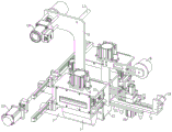
fig. 1 is a first perspective view of the present invention;
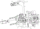
fig. 2 is a partial view of the mold mechanism of the present invention;
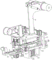
fig. 3 is a second perspective view of the present invention;
fig. 4 is a sectional view of the present invention.
In the figure: 1. a waste hopper; 2. pressing a bottom plate; 3. a receiving support; 4. a mould frame cylinder; 5. a lower die placing plate; 6. a lower die; 7. a waste pipe; 8. a reinforcing roller; 9. a cutter-interposing pad; 10. a first motor; 11. a first guide roller; 12. a cylinder block is attached; 13. a spring; 14. pulling a material rod; 15. a material clamping cylinder; 16. a material pulling cylinder; 17. a movable plate; 18. a second guide roller; 19. a material pressing plate; 20. a push cylinder; 21. pushing the plate; 22. an upper pressure plate; 23. a second motor; 24. a connecting plate; 25. a blade inserting blade; 27. a slide rail; 28. a page-feeding cylinder; 29. and a screw rod.
Detailed Description
The technical solutions in the embodiments of the present invention will be described clearly and completely with reference to the accompanying drawings in the embodiments of the present invention, and it is obvious that the described embodiments are only some embodiments of the present invention, not all embodiments. Based on the embodiments in the present invention, all other embodiments obtained by a person skilled in the art without creative work belong to the protection scope of the present invention.
Example 1
Referring to fig. 1-4, the present invention provides the following technical solutions: a
A dual mold reinforcement apparatus, comprising:
the lower inner wall of the lower cylinder seat 12 is fixedly connected with a lower cylinder 28, the upper end of the lower cylinder seat 12 is fixedly connected with a mounting plate through two connecting plates 24, and the side end of the lower cylinder seat 12 is fixedly connected with a movable plate 17;
the reinforcing mechanism comprises a clamping component and a blade component, and the clamping component and the blade component are both arranged on the lower side of the mounting plate to realize material reinforcement;
the two sets of die mechanisms are connected with the movable plate 17 to realize the punching operation of the material; and
and the material receiving mechanism is arranged on the upper side of the mounting plate so as to realize a reinforcing material receiving process.
In the embodiment of the present invention, the second motor 23 is started to drive the screw 29 to rotate, the guide rail 27 drives other components to slide on the two movable plates 17 along with the rotation of the screw 29, the material is placed on the upper end of the lower die 6, the die set cylinder 4 is started, the die set cylinder 4 pushes the upper press plate 22 to extrude the material downwards, the punch punches the material along with the upper press plate 22, the residual waste material after punching enters the waste material funnel 1 to be collected, the device punches the material through the die set cylinder 4, the waste material after punching is collected for other work, so that the environment after punching is more neat and more convenient for personnel to arrange the waste material, the material to be reinforced is placed on the upper end of the pressure plate 19, the pressure cylinder is started, the thin rod of the pressure cylinder fixes the material on the upper end of the pressure plate 19, the push cylinder 20 is started, promote cylinder 20 and promote to press material bottom plate 2 to reciprocate, adjust the height of pressing flitch 19, start the pulling cylinder, the pulling cylinder drives and presses material cylinder base to remove, removes the material to and intervene shim 9 and intervene and carry out further work between blade 25, and spring 13 promotes to intervene blade 25 and carry out the reinforcement operation, mends the intensity that enters into the improvement material with the material in this device, reduces the loss that the material caused in the operation of punching, and what need explain is: the specific model of the die carrier cylinder 4, the first motor 10, the next section cylinder seat 12, the clamping cylinder 15, the pulling cylinder 16, the pushing cylinder 20, the second motor 23, the next section cylinder 28, the screw 29 and the like is selected by the relevant technical personnel familiar with the field, and the die carrier cylinder 4, the first motor 10, the next section cylinder seat 12, the clamping cylinder 15, the pulling cylinder 16, the pushing cylinder 20, the second motor 23, the next section cylinder 28, the screw 29 and the like belong to the prior art, and the details are not repeated in the scheme.
Referring to fig. 4, the blade assembly includes a pressing plate 19, a pushing cylinder 20, a pushing plate 21, a pressing bottom plate 2, a knife blade 25, a knife pad 9 and a second guiding roller 18, the knife blade 25 is fixedly connected to the upper end of the thin rod of the spring 13 through a sliding plate, the knife pad 9 is fixedly mounted at the lower end of the mounting plate through a knife base, the pushing plate 21 is fixedly connected to the side end of the sliding plate, the pushing cylinder 20 is fixedly mounted at the lower end of the pushing plate 21, the pressing bottom plate 2 is fixedly connected to the upper end of the thin rod of the pushing cylinder 20, the second guiding roller 18 is fixedly connected to the upper end edge of the pressing bottom plate 2, the upper end of the pressing bottom plate 2 is slidably connected to a pressing cylinder base through a sliding rail, the upper end of the pressing cylinder base is fixedly connected to a pressing cylinder, the pressing plate 19 is disposed at the lower side of the pressing cylinder, the side end of one of the connecting plates 24 is fixedly connected with a pulling cylinder, and a thin rod of the pulling cylinder is connected with a base of the material pressing cylinder.
In this embodiment: the material that will need the reinforcement is placed the upper end of pressing flitch 19, start the material cylinder, the thin pole of pressing the material cylinder fixes the material in the upper end of pressing flitch 19, start promotion cylinder 20, promotion cylinder 20 promotes presses material bottom plate 2 to reciprocate, adjust the height of pressing flitch 19, start the pulling cylinder, the pulling cylinder drives presses the material cylinder base to remove, move the material to mediating knife pad 9 and mediate between blade 25 and carry out further work, spring 13 promotes to mediate blade 25 and carry out the reinforcement operation, mend into the intensity that improves the material with the material in this device, reduce the loss that the material caused in the operation of punching.
Referring to fig. 2, each set of mold mechanisms includes a waste funnel 1, a mold base cylinder 4, an upper platen 22, a lower mold placing plate 5, a lower mold 6, a plurality of springs 13, an upper mold plate and a lower mold plate, wherein the upper mold plate and the lower mold plate are both fixedly connected to the side end of a movable plate 17, the mold base cylinder 4 is fixedly connected to the upper end of the upper mold plate, the upper platen 22 is fixedly connected to the lower end of a thin rod of the mold base cylinder 4, the lower mold placing plate 5 is fixedly connected to the upper end of the lower mold plate, the plurality of springs 13 are fixedly connected between the upper platen 22 and the lower mold placing plate 5, the lower end of the upper platen 22 is provided with a plurality of punches, the lower ends of the plurality of punches are provided with a discharging plate, the lower mold 6 is fixedly connected to the upper end of the lower mold placing plate 5, and the waste funnel 1 is arranged at the lower end of the lower mold placing plate 5; the side ends of the upper and lower die plates in one set of die mechanism are fixedly connected with a die set side plate, and the side ends of the die set side plate are provided with two sets of isolating film guide roller assemblies.
In this embodiment: place the upper end of lower mould 6 with the material, start die carrier cylinder 4, die carrier cylinder 4 promotes top board 22 and extrudees the material downwards, the drift punches to the material along with top board 22, it gets into waste hopper 1 and is collected to punch remaining waste material, this device punches the operation to the material through die carrier cylinder 4, the waste material who has punched is collected and supplies other work to use for the environment behind the operation of punching is neatly more makes things convenient for personnel to arrange in order waste material.
Referring to fig. 1 specifically, the material receiving mechanism includes a material receiving support 3, a first guide roller 11, a first motor 10 and a material receiving roller, the material receiving support 3 is fixedly connected to the upper end of the mounting plate, the first motor 10 is fixedly connected to the side end of the material receiving support 3, the material receiving roller is rotatably connected to the other side end of the material receiving support 3, a rotating shaft of the material receiving roller is fixed to an output shaft of the first motor 10, and the first guide roller 11 is fixedly connected to the side end of the material receiving support 3; the upper end of the mounting plate is rotatably connected with a reinforcing roller 8 through a baffle plate.
In this embodiment: the material receiving structure automatically collects and conveys materials.
Referring to fig. 4 specifically, the clamping assembly includes a pulling rod 14, a clamping cylinder 15, a pulling cylinder 16, a pulling base, a clamping cylinder base and a pulling cylinder base, the pulling base is fixedly connected to the upper end of the movable plate 17, the pulling rod 14 is fixedly connected between the inner walls of the pulling base, the pulling cylinder base is slidably connected to the circumferential surface of the pulling rod 14, the clamping cylinder base is slidably connected between the inner walls of the pulling cylinder base, the clamping cylinder 15 is fixedly connected between the inner walls of the clamping cylinder base, the pulling cylinder 16 is fixedly connected to the upper end of the pulling cylinder base, and the thin rod of the pulling cylinder 16 is fixed to the upper end of the clamping cylinder base; the material clamping cylinder 15 is fixedly connected with two material clamps through thin rods.
In this embodiment: the material clamping assembly can clamp materials, and the next operation is convenient to perform.
Specifically referring to fig. 3, two guide rails 27 are disposed on one side of the movable plate 17, the movable plate 17 is slidably connected to the circumferential surface of the guide rails 27, a lead screw nut seat is fixedly connected to a side end of the movable plate 17, the second motor 23 is disposed on the front side of the movable plate 17, a lead screw 29 is fixedly connected to an output end of the spring 13, and the lead screw nut seat is threadedly connected to the circumferential surface of the lead screw 29 through a lead screw nut.
In this embodiment: the second motor 23 is started to drive the screw 29 to rotate, and along with the rotation of the screw 29, the guide rail 27 drives other components to slide on the two movable plates 17, and the movable plates 17 can drive the whole device to move, so that the operation at a moving position is facilitated.
Referring specifically to fig. 1, a waste pipe 7 is fixedly connected to a lower end of one of the waste hoppers 1.
In this embodiment: the waste material slides out from the waste material pipe 7, and is convenient to collect.
The utility model discloses a theory of operation and use flow: the second motor 23 is started to drive the screw rod 29 to rotate, the guide rail 27 drives other components to slide on the two movable plates 17 along with the rotation of the screw rod 29, materials are placed at the upper end of the lower die 6, the die set cylinder 4 is started, the die set cylinder 4 pushes the upper pressing plate 22 to extrude the materials downwards, the punch punches the materials along with the upper pressing plate 22, the punching residual waste materials enter the waste hopper 1 to be collected, the device punches the materials through the die set cylinder 4, the punched waste materials are collected for other work, so that the environment after punching is cleaner and more convenient for personnel to arrange the waste materials, the materials needing reinforcement are placed at the upper end of the pressure plate 19, the pressure cylinder is started, a thin rod of the pressure cylinder fixes the materials at the upper end of the pressure plate 19, the pushing cylinder 20 is started, the pushing cylinder 20 pushes the pressure plate 2 to move up and down, the height of material board 19 is pressed in the adjustment, starts the pulling cylinder, and the pulling cylinder drives presses material cylinder base to remove, removes the material and intervenes shim 9 and intervenes and carry out further work between blade 25, and spring 13 promotes to intervene blade 25 and carry out the reinforcement operation, mends into the intensity that improves the material with the material in this device, reduces the loss that the material caused in the operation of punching.
Finally, it should be noted that: although the present invention has been described in detail with reference to the foregoing embodiments, it will be apparent to those skilled in the art that modifications may be made to the embodiments described in the foregoing embodiments, or equivalents may be substituted for elements thereof. Any modification, equivalent replacement, or improvement made within the spirit and principle of the present invention should be included in the protection scope of the present invention.
Claims (7)
1. A double-die reinforcing device is characterized by comprising:
the lower inner wall of the lower cylinder seat (12) is fixedly connected with a lower cylinder (28), the upper end of the lower cylinder seat (12) is fixedly connected with a mounting plate through two connecting plates (24), and the side end of the lower cylinder seat (12) is fixedly connected with a movable plate (17);
the reinforcing mechanism comprises a material clamping component and a blade component, and the material clamping component and the blade component are both arranged on the lower side of the mounting plate to realize material reinforcement;
the two groups of die mechanisms are connected with the movable plate (17) to realize punching operation of materials; and
and the material receiving mechanism is arranged on the upper side of the mounting plate so as to realize a reinforcing material receiving process.
2. The dual-mold reinforcing apparatus of claim 1, wherein: the blade component comprises a pressure plate (19), a pushing cylinder (20), a push plate (21), a pressure bottom plate (2), a medium blade (25), a medium cutter pad (9) and a second guide roller (18), the medium blade (25) is fixedly connected to the upper end of a thin rod of a spring (13) through a sliding plate, the medium cutter pad (9) is fixedly arranged at the lower end of a mounting plate through a medium cutter base, the push plate (21) is fixedly connected to the side end of the sliding plate, the pushing cylinder (20) is fixedly arranged at the lower end of the push plate (21), the pressure bottom plate (2) is fixedly connected to the upper end of the thin rod of the pushing cylinder (20), the second guide roller (18) is fixedly connected to the edge of the upper end of the pressure bottom plate (2), the upper end of the pressure bottom plate (2) is slidably connected with a pressure cylinder base through a sliding rail, and the upper end of the pressure cylinder base is fixedly connected with a pressure cylinder, the material pressing plate (19) is arranged on the lower side of the material pressing cylinder, a pulling cylinder is fixedly connected to the side end of one of the connecting plates (24), and a thin rod of the pulling cylinder is connected with a base of the material pressing cylinder.
3. The dual-mold reinforcing apparatus of claim 2, wherein: each group of the die mechanisms comprises a waste hopper (1), a die set cylinder (4), an upper pressing plate (22), a lower die placing plate (5), a lower die (6), a plurality of springs (13), an upper die plate and a lower die plate, the upper die plate and the lower die plate are both fixedly connected to the side end of the movable plate (17), the die carrier cylinder (4) is fixedly connected to the upper end of the upper die plate, the upper pressure plate (22) is fixedly connected with the lower end of the thin rod of the die carrier cylinder (4), the lower die placing plate (5) is fixedly connected with the upper end of the lower die plate, a plurality of springs (13) are fixedly connected between the upper pressure plate (22) and the lower die placing plate (5), the lower end of the upper pressure plate (22) is provided with a plurality of punches, the lower ends of the punches are provided with stripper plates, the lower die (6) is fixedly connected to the upper end of the lower die placing plate (5), and the waste hopper (1) is arranged at the lower end of the lower die placing plate (5); the side ends of the upper die plate and the lower die plate in one group of die mechanisms are fixedly connected with a die set side plate, and two groups of isolating film guide roller assemblies are arranged at the side ends of the die set side plate.
4. The dual mold reinforcement apparatus of claim 3, wherein: the receiving mechanism comprises a receiving support (3), a first guide roller (11), a first motor (10) and a receiving roller, the receiving support (3) is fixedly connected to the upper end of the mounting plate, the first motor (10) is fixedly connected to the side end of the receiving support (3), the receiving roller is rotatably connected to the other side end of the receiving support (3), a rotating shaft of the receiving roller is fixed to an output shaft of the first motor (10), and the first guide roller (11) is fixedly connected to the side end of the receiving support (3); the upper end of the mounting plate is rotatably connected with a reinforcing roller (8) through a baffle.
5. The dual mold reinforcement apparatus of claim 4, wherein: the clamping assembly comprises a pulling rod (14), a clamping cylinder (15), a pulling cylinder (16), a pulling base, a clamping cylinder base and a pulling cylinder base, wherein the pulling base is fixedly connected to the upper end of a movable plate (17), the pulling rod (14) is fixedly connected between the inner walls of the pulling base, the pulling cylinder base is slidably connected to the circumferential surface of the pulling rod (14), the clamping cylinder base is slidably connected between the inner walls of the pulling cylinder base, the clamping cylinder (15) is fixedly connected between the inner walls of the clamping cylinder base, the pulling cylinder (16) is fixedly connected to the upper end of the pulling cylinder base, and a thin rod of the pulling cylinder (16) is fixed to the upper end of the clamping cylinder base; the material clamping cylinder (15) is fixedly connected with two material clamps through thin rods.
6. The dual mold reinforcement apparatus of claim 5, wherein: one side of fly leaf (17) is provided with two guide rails (27), fly leaf (17) sliding connection is in the circumferential surface of guide rail (27), the side fixedly connected with lead screw nut seat of fly leaf (17), the front side of fly leaf (17) is provided with second motor (23), the output fixedly connected with lead screw (29) of spring (13), lead screw nut seat passes through lead screw nut threaded connection in the circumferential surface of lead screw (29).
7. The dual mold reinforcement apparatus of claim 6, wherein: the lower end of one of the waste hoppers (1) is fixedly connected with a waste pipe (7).
Priority Applications (1)
| Application Number | Priority Date | Filing Date | Title |
|---|---|---|---|
| CN202121162952.5U CN214981552U (en) | 2021-05-27 | 2021-05-27 | Double-mold reinforcing device |
Applications Claiming Priority (1)
| Application Number | Priority Date | Filing Date | Title |
|---|---|---|---|
| CN202121162952.5U CN214981552U (en) | 2021-05-27 | 2021-05-27 | Double-mold reinforcing device |
Publications (1)
| Publication Number | Publication Date |
|---|---|
| CN214981552U true CN214981552U (en) | 2021-12-03 |
Family
ID=79087840
Family Applications (1)
| Application Number | Title | Priority Date | Filing Date |
|---|---|---|---|
| CN202121162952.5U Active CN214981552U (en) | 2021-05-27 | 2021-05-27 | Double-mold reinforcing device |
Country Status (1)
| Country | Link |
|---|---|
| CN (1) | CN214981552U (en) |
-
2021
- 2021-05-27 CN CN202121162952.5U patent/CN214981552U/en active Active
Similar Documents
| Publication | Publication Date | Title |
|---|---|---|
| CN110918771A (en) | Automatic stamping equipment of thin slice | |
| CN205463958U (en) | Vehicle vent -pipe throat mould | |
| CN114682722A (en) | Red punch online trimming mechanism | |
| CN209577853U (en) | A kind of cutting mould of auto-parts processing | |
| CN221493817U (en) | Machining stamping device | |
| CN102861817B (en) | Blanking moulding die for spring ring | |
| CN219193659U (en) | Automatic runner device of cutting of laser | |
| CN219402054U (en) | Ejection device for high-precision male and female die production | |
| CN221362381U (en) | Rotor sheet die capable of being synchronously ejected | |
| CN220028480U (en) | Quick stamping die | |
| CN207982034U (en) | An easy-to-use metal stamping die | |
| CN219443214U (en) | Demoulding mechanism of automobile part stamping die | |
| CN207447161U (en) | Car Change-speed Gear Box Binding Gear decompressor | |
| CN114054566B (en) | A convenient maintenance automobile parts stamping device | |
| CN117380842A (en) | High-precision sheet metal stamping die easy to demould | |
| CN214556407U (en) | A profile shaping machine | |
| CN213671449U (en) | Combined stretching die | |
| CN108637064B (en) | A multi-functional high-efficiency auto parts stamping forming machine | |
| CN223686067U (en) | Vertical punching powder forming device | |
| CN223129059U (en) | Efficient continuous stamping die tooling mechanism | |
| CN221415020U (en) | Powder metallurgy forming die with easily detachable and replaceable accessories | |
| CN218227571U (en) | Plastic molding machine with positioning structure | |
| CN219445878U (en) | Sun shield mould | |
| CN212857396U (en) | Automobile parts stop gear blanking mould | |
| CN220464464U (en) | Rubber mold stub bar ejection mechanism |
Legal Events
| Date | Code | Title | Description |
|---|---|---|---|
| GR01 | Patent grant | ||
| GR01 | Patent grant |