CN219186451U - Air purification device for steel pipe pickling workshop - Google Patents
Air purification device for steel pipe pickling workshop Download PDFInfo
- Publication number
- CN219186451U CN219186451U CN202320333500.1U CN202320333500U CN219186451U CN 219186451 U CN219186451 U CN 219186451U CN 202320333500 U CN202320333500 U CN 202320333500U CN 219186451 U CN219186451 U CN 219186451U
- Authority
- CN
- China
- Prior art keywords
- fixedly connected
- wall
- box body
- box
- steel pipe
- Prior art date
- Legal status (The legal status is an assumption and is not a legal conclusion. Google has not performed a legal analysis and makes no representation as to the accuracy of the status listed.)
- Active
Links
Images


Landscapes
- Cleaning And De-Greasing Of Metallic Materials By Chemical Methods (AREA)
Abstract
The utility model relates to the technical field of air purification and discloses an air purification device for a steel pipe pickling workshop, which comprises a box body, wherein an air inlet pipe is formed in the surface of the box body and is communicated with an air outlet end of an external fan, an installation column is fixedly connected to the inner bottom wall of the box body, a diversion box is fixedly connected to the top end of the installation column, an atomizing nozzle is mounted on the upper surface of the diversion box, a water pump is fixedly connected to the surface of the box body, and the liquid inlet end of the water pump extends to the inner bottom of the box body through a pipeline. According to the utility model, the installation tube, the connecting tube, the installation frame, the T-shaped rubber disc and the first spring are arranged, the T-shaped rubber disc can block the connecting tube, gas is prevented from being directly discharged through the connecting tube and the installation tube, the purifying time of the gas in the box body is prolonged, after the pressure in the box body is increased, the pressure pushes the T-shaped rubber disc to move upwards, and the gas is discharged, so that the device increases the time of single treatment of the gas, and the treatment effect is improved.
Description
Technical Field
The utility model relates to the technical field of air purification, in particular to an air purification device for a steel pipe pickling workshop.
Background
The publication No. CN216418909U discloses an air purification device for a steel pipe pickling workshop, which is characterized in that the existing metal surface treatment, especially the steel pipe hot dip galvanizing pretreatment, is required to be pickled and derusted, the pickling process is generally required to be heated, acid liquor can form very large acid mist under a high-temperature environment, if the acid mist is directly discharged into the air, the air containing the acid mist is unnecessarily polluted, the air is required to be discharged after being absorbed, the existing acid mist neutralization tower cannot effectively control the tail gas acid mist content, the complete absorption can only be carried out by increasing the number of the neutralization towers, the energy consumption is increased, and the sprayed liquid drops are relatively large, and also very consume alkali and production water, so that the acid mist treatment condition can be mastered at any time through a remote controller, and the numerical control of the acid mist neutralization tower is detected through a pH detector to work; the traditional spray liquid drops are large, and the contact with acid mist is less, but the alkali mist is adopted to absorb the acid mist, so that the contact area is large, the absorption efficiency is high, more water and alkali are saved compared with the traditional spray acid mist absorption mode, and the production cost is reduced.
As can be seen from fig. 1, the outside air enters the neutralization tower, the sprayed neutralization liquid is neutralized and directly enters the next neutralization tower through the pipeline, the residence time of the outside air in the neutralization tower is longer, the contact time of the air and the neutralization liquid is shortened, the neutralization effect is deteriorated, and a plurality of neutralization towers are needed to be matched for use, so that the construction cost is increased.
Disclosure of Invention
In order to overcome the defects in the prior art, the utility model provides an air purifying device for a steel pipe pickling workshop, which aims to solve the problems in the prior art.
The utility model provides the following technical scheme: the utility model provides a steel pipe pickling workshop air purification device, includes the box, the intake pipe has been seted up on the surface of box, the intake pipe communicates with the end of giving vent to anger of outside fan, the interior bottom wall fixedly connected with erection column of box, the top fixedly connected with reposition of redundant personnel case of erection column, the last surface mounting of reposition of redundant personnel case has the atomizer, the surface fixedly connected with water pump of box, the feed liquor end of water pump extends to the interior bottom of box through the pipeline, the play liquid end of water pump extends to the inside of reposition of redundant personnel case through the pipeline;
the utility model discloses a box, including box, mounting tube, connecting hole's inner wall fixedly connected with connecting tube, mounting tube's inner wall sliding connection has the mounting bracket, mounting bracket's lower fixed surface has T shape rubber dish, mounting bracket's upper surface fixedly connected with first spring, the top of first spring and mounting tube's interior roof fixed connection, T shape rubber dish's lower surface and mounting tube's interior bottom wall support tightly, the connecting hole has been seted up at mounting tube's top, connecting hole's inner wall fixedly connected with spring pipe, spring pipe's top fixedly connected with connecting pipe.
Further, the upper surface of box fixedly connected with returns shape cover, and the surface fixedly connected with of installation tube returns the shaped plate.
Further, the surface of the return plate is overlapped with the inner wall of the return cover.
Further, the cavity is seted up to the inside of returning shape cover, and the inner wall sliding connection of cavity has the sliding plate, and the one side fixedly connected with cambered surface piece that the sliding plate is close to the returning shape board, and the sliding port with the cavity intercommunication has been seted up to the inner wall of returning shape cover, and the surface of cambered surface piece and the inner wall overlap joint of sliding port, and the grafting groove has been seted up to the side of returning shape board, and the surface of cambered surface piece and the inner wall overlap joint of grafting groove.
Further, the upper surface of the cambered surface block is arc-shaped.
Further, one side of the sliding plate far away from the cambered surface block is fixedly connected with a T-shaped rod and a second spring respectively, the end face of the second spring is fixedly connected with the inner wall of the cavity, a sliding hole is formed in the side face of the loop-shaped cover, and the surface of the T-shaped rod is overlapped with the inner wall of the sliding hole.
The utility model has the technical effects and advantages that:
1. according to the utility model, the installation tube, the connecting tube, the installation frame, the T-shaped rubber disc and the first spring are arranged, the T-shaped rubber disc can block the connecting tube, gas is prevented from being directly discharged through the connecting tube and the installation tube, the purifying time of the gas in the box body is prolonged, after the pressure in the box body is increased, the pressure pushes the T-shaped rubber disc to move upwards, and the gas is discharged, so that the device increases the time of single treatment of the gas, and the treatment effect is improved.
2. According to the utility model, the arrangement of the loop-shaped cover, the loop-shaped plate, the sliding plate, the cambered surface block, the T-shaped rod and the second spring is convenient for the disassembly and assembly of the installation tube and the replacement of the installation tube.
Drawings
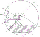
FIG. 1 is a schematic view of the front cross-section structure of the present utility model.
Fig. 2 is an enlarged schematic view of the structure of fig. 1 a according to the present utility model.
Fig. 3 is a schematic perspective view of the mounting frame of the present utility model.
The reference numerals are: the novel spray head comprises a box body 1, a mounting column 2, a distribution box 3, an atomization spray head 4, a water pump 5, a mounting tube 6, a connecting cylinder 7, a mounting frame 8, a 9T-shaped rubber disc, a first spring 10, a spring tube 11, a connecting tube 12, a return cover 13, a return plate 14, a sliding plate 15, a cambered surface block 16, a T-shaped rod 17 and a second spring 18.
Detailed Description
The embodiments of the present utility model will be clearly and completely described below with reference to the drawings in the present utility model, and the configurations of the structures described in the following embodiments are merely examples, and the air cleaning device for a steel pipe pickling plant according to the present utility model is not limited to the structures described in the following embodiments, and all other embodiments obtained by a person skilled in the art without any inventive effort are within the scope of the present utility model.
Referring to fig. 1-3, the utility model provides an air purifying device for a steel pipe pickling workshop, which comprises a box body 1, wherein an air inlet pipe is formed in the surface of the box body 1 and is communicated with an air outlet end of an external fan, an installation column 2 is fixedly connected to the inner bottom wall of the box body 1, and a diversion box 3 is fixedly connected to the top end of the installation column 2.
The upper surface mounting of reposition of redundant personnel case 3 has atomizer 4, and the fixed surface of box 1 is connected with water pump 5, and the feed liquor end of water pump 5 passes through the interior bottom of pipeline extension to box 1, and the liquid outlet end of water pump 5 passes through the inside of pipeline extension to reposition of redundant personnel case 3, and the upper surface detachable of box 1 installs mounting tube 6, and the bottom fixedly connected with rubber circle of mounting tube 6, the lower surface of rubber circle supports with the upper surface of box 1 tightly.
The water pump 5 conveys the neutralization liquid in the box body 1 to the diversion box 3 and sprays the neutralization liquid through the atomization spray head 4, external air enters the box body 1 through the air inlet pipe, and the air is mixed with the sprayed liquid for neutralization.
The upper surface fixedly connected with of box 1 returns shape cover 13, and the fixed surface of installation tube 6 is connected with the shape of returning 14, returns the surface of shape of returning 14 and the inner wall overlap joint of shape of returning cover 13, and the cavity has been seted up to the inside of shape of returning cover 13, and the inner wall sliding connection of cavity has sliding plate 15, and one side that sliding plate 15 is close to shape of returning 14 is fixedly connected with cambered surface piece 16, and the sliding port with cavity intercommunication has been seted up to the inner wall of shape of returning cover 13.
The surface of cambered surface piece 16 and the inner wall overlap joint of sliding port, the spliced eye has been seted up to the side of return shoe 14, the surface of cambered surface piece 16 and the inner wall overlap joint of spliced eye, the upper surface of cambered surface piece 16 is the arc, the one side that cambered surface piece 16 was kept away from to the sliding plate 15 is fixedly connected with T shape pole 17 and second spring 18 respectively, the terminal surface and the inner wall fixed connection of cavity of second spring 18, the sliding hole has been seted up to the side of return shoe 13, the surface of T shape pole 17 and the inner wall overlap joint of sliding hole.
The T-shaped rod 17 is pulled, the cambered surface block 16 is pulled out of the inserting groove by the T-shaped rod 17, the mounting pipe 6 can be taken down, the return-type plate 14 is pressed down after the new mounting pipe 6 is replaced, the return-type plate 14 is overlapped with the cambered surface of the cambered surface block 16, the cambered surface block 16 is automatically retracted into the cavity, and after the return-type cover 13 is completely placed, the cambered surface block 16 is pushed by the elastic force of the second spring 18 to be inserted into the inserting groove to complete fixation.
The mounting hole has been seted up to the bottom of installation tube 6, the inner wall fixedly connected with connecting tube 7 of mounting hole, the inner wall sliding connection of installation tube 6 has mounting bracket 8, the lower fixed surface of mounting bracket 8 has T shape rubber dish 9, the last fixed surface of mounting bracket 8 has first spring 10, the top of first spring 10 and the interior roof fixed connection of installation tube 6, the lower surface of T shape rubber dish 9 supports tightly with the interior bottom wall of installation tube 6, the connecting hole has been seted up at the top of installation tube 6, the inner wall fixedly connected with spring pipe 11 of connecting hole, the top fixedly connected with connecting pipe 12 of spring pipe 11.
T shape rubber dish 9 can block connecting tube 7, avoids gas directly to pass through connecting tube 7 and 6 discharges of installation tube, increases the time that gas purified in box 1 inside, and after the inside pressure of box 1 increases, pressure promotes T shape rubber dish 9 and reciprocates, and gas discharge to make the device increase the time of gaseous single treatment, increase the treatment effect.
The last points to be described are: first, in the description of the present application, it should be noted that, unless otherwise specified and defined, the terms "mounted," "connected," and "connected" are to be construed broadly, and may be mechanical or electrical, or may be a direct connection between two elements, and "upper," "lower," "left," "right," etc. are merely used to indicate relative positional relationships, which may be changed when the absolute position of the object being described is changed;
secondly: in the drawings of the disclosed embodiments, only the structures related to the embodiments of the present disclosure are referred to, and other structures can refer to the common design, so that the same embodiment and different embodiments of the present disclosure can be combined with each other under the condition of no conflict;
finally: the foregoing description of the preferred embodiments of the utility model is not intended to limit the utility model to the precise form disclosed, and any such modifications, equivalents, and alternatives falling within the spirit and principles of the utility model are intended to be included within the scope of the utility model.
Claims (6)
1. The utility model provides a steel pipe pickling workshop air purification device, includes box (1), its characterized in that: an air inlet pipe is formed in the surface of the box body (1), the air inlet pipe is communicated with an air outlet end of the external fan, an installation column (2) is fixedly connected to the inner bottom wall of the box body (1), a distribution box (3) is fixedly connected to the top end of the installation column (2), an atomization nozzle (4) is mounted on the upper surface of the distribution box (3), a water pump (5) is fixedly connected to the surface of the box body (1), the liquid inlet end of the water pump (5) extends to the inner bottom of the box body (1) through a pipeline, and the liquid outlet end of the water pump (5) extends to the inside of the distribution box (3) through a pipeline;
the utility model discloses a box, including box (1), mounting tube (6) are installed to upper surface detachable, the mounting hole has been seted up to the bottom of mounting tube (6), the inner wall fixedly connected with connecting tube (7) of mounting hole, the inner wall sliding connection of mounting tube (6) has mounting bracket (8), the lower fixed surface of mounting bracket (8) has T shape rubber dish (9), the upper surface fixedly connected with first spring (10) of mounting bracket (8), the top and the interior roof fixed connection of mounting tube (6) of first spring (10), the lower surface of T shape rubber dish (9) supports tightly with the interior bottom of mounting tube (6), the connecting hole has been seted up at the top of mounting tube (6), the inner wall fixedly connected with spring pipe (11) of connecting hole, the top fixedly connected with connecting pipe (12) of spring pipe (11).
2. An air cleaning device for a steel pipe pickling plant according to claim 1, characterized in that: the upper surface of the box body (1) is fixedly connected with a square cover (13), and the surface of the mounting pipe (6) is fixedly connected with a square plate (14).
3. An air cleaning device for a steel pipe pickling plant according to claim 2, characterized in that: the surface of the return-shaped plate (14) is overlapped with the inner wall of the return-shaped cover (13).
4. A steel pipe pickling plant air cleaning device according to claim 3, characterized in that: the inside of returning shape cover (13) has seted up the cavity, and the inner wall sliding connection of cavity has sliding plate (15), and one side fixedly connected with cambered surface piece (16) that sliding plate (15) is close to returning shape board (14), and the sliding port with the cavity intercommunication has been seted up to the inner wall of returning shape cover (13), and the surface of cambered surface piece (16) and the inner wall overlap joint of sliding port, and the jack groove has been seted up to the side of returning shape board (14), and the surface of cambered surface piece (16) and the inner wall overlap joint of jack groove.
5. An air cleaning device for a steel pipe pickling plant according to claim 4, wherein: the upper surface of the cambered surface block (16) is arc-shaped.
6. An air cleaning device for a steel pipe pickling plant according to claim 5, wherein: one surface of the sliding plate (15) far away from the cambered surface block (16) is fixedly connected with a T-shaped rod (17) and a second spring (18) respectively, the end surface of the second spring (18) is fixedly connected with the inner wall of the cavity, a sliding hole is formed in the side surface of the rectangular cover (13), and the surface of the T-shaped rod (17) is overlapped with the inner wall of the sliding hole.
Priority Applications (1)
| Application Number | Priority Date | Filing Date | Title |
|---|---|---|---|
| CN202320333500.1U CN219186451U (en) | 2023-02-23 | 2023-02-23 | Air purification device for steel pipe pickling workshop |
Applications Claiming Priority (1)
| Application Number | Priority Date | Filing Date | Title |
|---|---|---|---|
| CN202320333500.1U CN219186451U (en) | 2023-02-23 | 2023-02-23 | Air purification device for steel pipe pickling workshop |
Publications (1)
| Publication Number | Publication Date |
|---|---|
| CN219186451U true CN219186451U (en) | 2023-06-16 |
Family
ID=86713665
Family Applications (1)
| Application Number | Title | Priority Date | Filing Date |
|---|---|---|---|
| CN202320333500.1U Active CN219186451U (en) | 2023-02-23 | 2023-02-23 | Air purification device for steel pipe pickling workshop |
Country Status (1)
| Country | Link |
|---|---|
| CN (1) | CN219186451U (en) |
-
2023
- 2023-02-23 CN CN202320333500.1U patent/CN219186451U/en active Active
Similar Documents
| Publication | Publication Date | Title |
|---|---|---|
| CN219186451U (en) | Air purification device for steel pipe pickling workshop | |
| CN200942381Y (en) | Simple environment-protecting energy-saving type spray box | |
| CN219400646U (en) | Liquid atomization spraying device applied to cleaning robot | |
| CN209696548U (en) | A kind of sprayer fog gun machine equipment of environmental protection dust suppression deodorization purification epidemic prevention | |
| CN205032067U (en) | Flue gas desulfurization purifier | |
| CN213942623U (en) | Organic peculiar smell treatment device with Venturi type spray tower | |
| CN209333488U (en) | A kind of high efficiency denitration device being uniformly mixed convenient for flue gas with ammonia | |
| CN216159207U (en) | Spraying cooling device for prefabricated house | |
| CN213408216U (en) | Spraying rotational flow combined desulfurization device | |
| CN211725307U (en) | Environment-friendly corrosion-resistant polymer spray tower | |
| CN215196193U (en) | Spray tower with centralized spray header | |
| CN210033467U (en) | Device of mould maintenance rack is followed to tunnel lining platform truck | |
| CN220513829U (en) | Improved structure device of spray head of acid mist purifying tower | |
| CN202762294U (en) | Acid mist purification device | |
| CN2241584Y (en) | Simple sprayer | |
| CN217247992U (en) | Cleaning tail gas treatment device for touch screen functional sheet | |
| CN216395797U (en) | Acid mist absorption tower with anti-corrosion effect | |
| CN215352927U (en) | Novel glass fiber reinforced plastic purification tower for treating acid mist waste gas | |
| CN220877770U (en) | Acrylic ester rectifying column | |
| CN218077234U (en) | Vertical spray tower | |
| CN211725129U (en) | Air-assisted water atomization nozzle and spray cooling system | |
| CN209204988U (en) | A kind of multiple-unit high-efficient washing tower | |
| CN220609796U (en) | Injector unit for SNCR denitration system | |
| CN216223751U (en) | Leather waste gas deodorization system of clean production | |
| CN214051137U (en) | External nozzle assembly of chemical spray tower quick detach for exhaust-gas treatment |
Legal Events
| Date | Code | Title | Description |
|---|---|---|---|
| GR01 | Patent grant | ||
| GR01 | Patent grant |